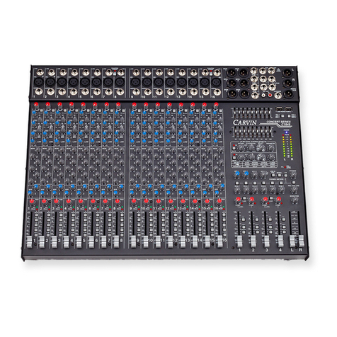
CARVIN SL User manual

SL24
SL40
SL56
Revision 1
76-00024
SERIES
STUDIO / LIVE
Owners Manual

Introduction
Sound Quality and In-Line Flexibility
There are a multitude of considerations that a sound engineer must weigh when choosing the right console. Whether the
console will be used for live sound reinforcement or studio recording, ultimately the choice of a console always focuses on
sound quality and signal routing flexibility. These were primary design considerations for the new S/L series consoles from
Carvin.
Sound
Carvin’s S/L consoles feature the ultimate Analog Devices SSM2017 mic/line preamp (on each
channel). Other major console manufacturers sometimes offer this pre-amp as an
upgrade option. In order to preserve the pristine signal quality of the
S/L’s preamp circuits throughout the signal path, Carvin utilized
surface mount P.C. technology with expensive high quality
surface mount components and high slew rate op-
amps. The S/L’s ingenious design features extremely
large ground traces, double sided, plated-through
FR4 military spec circuit boards and other design
aspects normally found in only the most expensive world class
consoles. As a result, the S/L series consoles offer some of the finest EIN,
headroom, cross-talk and S/N specs of any console regardless of size or price! The S/L’s 4-
band EQ section features two semi-parametric mid band and EQ in/out switching, as well as Lo-cut switching. The sweet
sound of this EQ cannot be overstated. Carvin spent a great deal of time and effort to ensure that the delicate subtleties of the
incoming signals are not disturbed by the EQ section, but that the character and flavor of the original signal be enhanced. The
warmth & intensity of the new S/L consoles from Carvin are startling! Respective of any other console you may have been con-
sidering (for either live sound or recording), Carvin promises you will not find a better sounding console!
Signal Routing and Capabilities
Like any exceptional recording console, the S/L consoles offer advanced In-Line signal routing. The S/L consoles easily meet
both pre and post production studio requirements, as well as offering additional ruggedness and special routing capabilities
normally reserved for live sound mixing. If you are an experienced sound engineer, we invite you to review the signal routing
and flexibility of this console for either application. Carvin is always eager to answer any questions you may have regarding
the S/L console and how it will solve your specific needs. Even if you are just a novice, be assured the intelligent design and
flexibility of the new S/L series consoles will meet all your sound needs and will allow you to discover aspects of your mixes
you may not have even considered.
The channel format of the S/L consoles offers some unique features and capabilities.
Just a few (for your consideration) are as follows:
1) Phase Switch (per channel): Most mixes neglect the very important aspect of proper phase. When utilizing multiple micro-
phones and signal sources, it is imperative that the final mixed signal be properly “in-phase”. The sound in the room and on
each microphone may be dynamic and lively, but when the final mix is accomplished the sound can become dull and lacking
brilliance. The close proximity of multiple microphones recording the same source can result in a mix that sounds muddy or
boxey. The channel phase switch on each mic channel ensures that your mixes will remain as brilliant and lively as the original
instrument.
2) Channel Tape Switch - This function allows you to quickly configure your console for multi-track mixdown. By pressing the
TAPE switch, your multi-track tape returns signal flow through the normal channel signal path for EQ, effects and basic post
production mixdown.
2
Studio Live Consoles

3) Tape Selection for Buses 5 & 6 and 7 & 8 (depending upon the selection of the Input Tape Switch) allows interconnecting
either the tape input signal or the mic input to these buses. Depending upon the configuration of your console, this switch will
allow for individual bus routing for quick overdubbing while simultaneously setting up the stereo control room mix. For most
recording situations, the input tape switch will be routing the mic signal through the channel and then (from the direct output)
to the multi-track tape deck. The output of the multi-track tape deck is then fed back into the tape inputs of the channel and
the tape switches will be depressed for buses 5&6 (for the studio headphone mixes) and for buses 7&8 for tape monitoring
and stereo control room monitoring. In this configuration, punch-ins are a snap and a quick rough tape mix is automatic. The
S/L consoles can accomplish just about any special signal routing requirement you may have. But, there is one aspect of the
tape switch that is not normally considered. On the S/L console, you can use the channel tape input as a line input! You can
then select the tape switch and route the signal to the stereo bus 7&8. From the 7&8 stereo bus output, you can select the L/R
switch to route the signal back to the console’s L/R master faders. This this feature will configure your 24 input console to a
48 input console (more if you have a 40 or 56 channel) with 24 mic pre’s and 24 additional line -ins! Yet another fantastic and
unique feature of the Carvin S/L series consoles!
4) Channel Solo & PFL - The S/L consoles are capable of both solo and PFL (Pre Fader Listen) monitoring. For live applica-
tions you may wish to configure your console for PFL (especially while setting up the system). But, you may decide that you
prefer to have the function of the S/L’s “solo-in-place” as you progress with your mix. Solo-in-place means that you can moni-
tor the exact level as it is placed in the stereo field. The ability to quickly configure your console for either type of monitoring is
both unique and yet another advanced feature of the S/L series consoles.
The above features are only a few of the unique options offered by the S/L console yet there are so many advanced capabilities
such as:
Aux send switching to the XLR balanced outputs (for balanced signal sends especially useful for live sound reinforcement)
Stereo Subgroup to L/R interconnects
Control Room to Studio Output selection
Fully isolated power supply utilizing a heavy-duty Speakon™ cable
We simply cannot explain all the configurations and capabilities of these extremely versatile consoles in this short introduc-
tion. We encourage you to read the manual and if you have questions call and allow our product experts help direct you to the
advanced features available with the S/L series. Without a doubt Carvin’s new S/L consoles represent a significant advance-
ment in home studio as well as live sound mixing. The fact that they are value priced is just another bonus you receive from
your new Carvin S/L series console.
3

RECEIVING INSPECTION—read before getting started
INSPECT YOUR MIXER FOR ANY DAMAGE which may have occurred during shipping. If any damage is found,
please notify the shipping company and CARVIN immediately.
SAVE THE CARTON & ALL PACKING MATERIALS. In the event you have to re-ship your unit, the S/L console
will only be accepted in our factory designed shipping carton or damage could result in which CARVIN and the ship-
ping company are not responsible for.
SAVE YOUR INVOICE. It will be required for warranty service if needed in the future.
SHIPMENT SHORTAGE. If you find items missing, they may have been shipped separately. Please allow several
days for the rest of your order to arrive before inquiring.
RECORD THE SERIAL NUMBER on the enclosed warranty card and on this manual for your records. Keep your
portion of the card and return the portion with your name and comments to us.
For the new owner
Congratulations on your selection of a Carvin product “The Professional's Choice.” Your S/L series console
demonstrates Carvin's commitment to producing the highest quality & most sophisticated engineering in the audio
industry today. Its wide acceptance and use by industry professionals illustrates the basis for Carvin's recognition
as “The Professional's Choice.”
Professionalism can only be measured from the results people achieve through their efforts and knowledge. It is
not something that automatically happens when buying new or more sophisticated equipment. Rather, it's what
you do with the equipment and how well you do it that ultimately makes the point. We are certain your new
CARVlN console will deliver the performance necessary for you to achieve solid results, and ultimately enjoy a high
degree of professionalism.
To compliment your new console and help you acquire that knowledge, we've included this manual. All of the
information you need to be up and running is right here! You'll find using this manual easy and convenient.
We've gone to great lengths to make it so. We've attempted to present the technical aspects of your new console
accurately and in “plain English”. But, if you have any questions that are not answered here, please call us at our
toll free numbers. Our sales staff is well versed in the technical aspects of our products and are waiting to assist
you with any questions you may have. We sincerely wish to ensure your complete satisfaction and enjoyment with
your new console.
If you would like to comment on features or performance of your new console, please feel free to contact us.
Comments from our customers have always helped us improve and further develop our products. We sincerely
welcome any comments or ideas you may have.
Please, send in the warranty card. Although it is not absolutely necessary to ensure warranty protection, it will
allow us to better know how you are using our equipment while keeping a ready reference for our files. Sending in
the warranty card also helps us to mail literature and information that may be of interest to you as a professional
musician. Let us know where you are so we can keep in touch!
In this manual there are diagrams and descriptions to aid you in understanding your new console. So, with this
manual in hand, you hold the key to proper operation and the ability to achieve professional results.
May you enjoy many years of success and fun with your new CARVIN console!
TOLL FREE (800)-854-2235
4
For your records, you may wish to record the following information.
Serial No._____________________ Invoice Date_______________

Quick set up - Before power is turned on.
1) Be sure the SLP5600 power supply and AC cord is correct for your region (120 Volt or 230 volt).
2) Use only a grounded (3 prong) power outlet to prevent a shock hazard. This also provides the qui-
etest grounding for your mixer.
3) Zeroing the console knobs and switches insures the current status of your mixer and reduces sur-
prises when initially plugging in instruments and microphones.
Zeroing procedure:
Channel - Turn all EQ gain controls to their center positions.
Turn the mic-pre gain controls to their full counter-clockwise position.
Turn all auxiliary send controls counter-clockwise to “0”.
Place channel faders to the down position.
Place all channel switches to the up position.
Master - Place all master and group faders to the down position.
Turn all control room levels counter clockwise to “0”
Turn all Auxiliary send master levels counter clockwise to “0”.
Turn all stereo return levels counter clockwise to “0”.
4) The SL mixer series uses an external power supply, the SLP5600.
AC power is connected to the SLP5600 and is in turn connected to
the mixer via a 4 wire Speakon™ cable. If an alternate Speakon™
cable is to be used, be sure it is a 4 wire cable. Not all Speakon™
cables have 4 wires.
5) After connecting your power supply and zeroing the console, turn on the mixer via the red power
switch on the SLP5600 power supply. Test the mixer by plugging a microphone into a channel XLR
input, turn up the gain control at the top of the channel and turn up the channels fader. While talking
into the microphone, the channel meters should be showing signal. Some adjustment to the gain con-
trol and fader may be needed to see the signal on the channel meters. Now assign the channel to any
of the master groups or Left-Right via the channel assignment switches 1-2, 3-4, 5-6, 7-8, or L-R.
After adjusting the corresponding master fader, the master meters should be showing signal.
This is a very simple turn on/setup procedure. However, be sure to read the entire manual. Note;
some features or setup connections may help in your situation because most of the S/L console fea-
tures are not clear cut Studio or Live functions.
5
7/8
GAIN
HIGH
AUX
SOLO
1-2
3-4
5-6
7-8
L-R
PRE
1-2
C
L
R
-
15
0
+
15
1k
2
00 5k
800
2k
FREQ
0
10
5
0
10
5
0
10
5
0
10
5
0
10
5
0
10
5
0
10
5
5
55
-
15
0
+
15
-
15
LOW
0
+
15
HI
MID
500
80 2k
200
1k
-
15
0
+
15
LOW
MID
MUTE
SOLO
LOW
CUT
PK
3
6
5
4
1
2
FREQ
PAN
78
C
PAN
PRE
FAD
w/EQ
E
T
A
P
6
-
5
E
T
A
P
N
I
Q
E
E
T
A
P
ES
AH
P
P
R
E
43
-
12
+12
+
9
24
+
6
+
3
0
6
18
3
oo
30
40
50
Set your channel controls as shown.

TABLE OF CONTENTS
Introduction . . . . . . . . . . . . . . . . . . .pg 2
a) Receiving Inspection
b) For the new owner
c) Before power is turned on
1. Mixer Overview . . . . . . . . . . . . . .pg 7
2. Installation . . . . . . . . . . . . . . . . .pg 7
3. Input Channel Section . . . . . . . . . .pg 8
4. Master Section . . . . . . . . . . . . . .pg 11
Master I/O section
Left, Right, and Groups
Control Masters
Stereo Returns & Tape IN/OUT
Auxiliary Send Masters
5. Standard Studio Mixer Setups . . . .pg 14
6. Standard Live Mixer Setups . . . . .pg 17
7. Using the Inserts . . . . . . . . . . . . .pg 22
Standard Inserting
Insert as Direct Mic-pre Out
8. Meter Bridge . . . . . . . . . . . . . . .pg 23
9. Power Supply . . . . . . . . . . . . . . .pg 24
10. Cable Connections . . . . . . . . . . .pg 25
11. Block Diagram . . . . . . . . . . . . .pg 26
12. General Specifications . . . . . . . .pg 27
Appendixes
B. Schematics . . . . . . . . . . . . .pgs 28-33
C. Console Dimensions . . . . . . . . . .pg 34
D. Glossary of Terms . . . . . . . . .pgs 35-37
6

1. Mixer Overview
The S/L series mixing consoles are designed for Studio and Live performances. S/L series consoles allow the user to perform
multi-track recording where the tracks equal the number of channels for the mixer; either 24, 40, or 56. This ability is due to the
Dual In-line channel format used on the S/L series. Dual In-line channels provide a mixing path for the microphones or other
input devices to be recorded, a mixing path for the individual channel outputs to a recording device’s inputs and finally a mixing
path for the output of the recording device. Live performances benefit from the S/L’s AUX sends that can be used for monitor
mixes or effects processing.
The SL consoles are equipped with :
• 24, 40, 56 channel frames.
• Low noise mic-pre amps EIN=128dB min.
• 4 band, dual mid sweep, Channel EQ.
• 8 auxiliary sends: 2 pre, 2 pre/post, 2 post, (stereo) pre/post fader.
• 4 stereo returns w/ Aux 1 & 2 sends, pan and level.
• 8 master groups w/ L-R, assignment and pan, mute and solo.
• Comprehensive master control room section with separate studio controls.
• Specially designed high current headphone outputs.
2. Installations
7
The S/L series console dimensions are in Appendix B for table size and custom installments. A good installation will keep in
mind placement proximity to potential noise sources and positioning the mixer where the sound can be heard clearly from the
audience’s perspective.
The outboard SLP5600 AC power supply is also a consideration when installing a console of this caliber. The AC power for the
mixer and the rest of the sound system needs to first of all, have the capacity to power the system. Be sure power amps and other
high power portions of the system are on large enough and, if possible, separate breakers. It’s possible to lose one or two power
amps in a large system and deal with a 3-6 dB drop in output but if the power amp takes the mixing console with it, you’ve lost
everything. Also, with AC power try to avoid using the same power outlets used by stage lighting. The performance lights typi-
cally require large amounts of power and produce heavy AC power spikes when switched on and off. These lights and many ban-
quet room lights can be on solid state dimmer controllers, which produce noisy spikes on their AC power lines. These noises can
only cause headaches for a sound system and nightmares for a recording studios because some of the spikes are emitted and
can’t be taken out by power conditioners.
The placement of the mixing console in live sound situations is often misunderstood. Especially when a promoter or banquet
director sees the console as taking up valuable floor space or as an eye sore at a fancy show. The placement of the mixing con-
sole is very important in hearing the performance from the perspective of the listeners. The placement for routing cables is fairly
obvious, avoid large power transformers, air conditioners and lighting rigs! Note: the best sound location in a room will be near
the console because that’s where the mix is created.

8
3. Input Channel section
1. 48V PHANTOM POWER SWITCH
This switch provides phantom power for condenser mics in groups of 8 channels. This allows other channel groups to remain
non-powered for instruments and dynamic mics that don’t require phantom power. The 48V switch should not be engaged when
using sources that do not use phantom power.
2. CHANNEL DIRECT OUT
The DIRECT OUT is a 1/4” TRS (Tip/Ring/Sleeve) balanced output. The DIRECT OUT provides an output of the channel (post
fader) unaffected by the pan or assignments. This is typically used for multi-track recording where each channel feeds a track
on the recorder. The DIRECT OUT can also be used for sending a channel to an effects unit and to return the effects unit to
another channel for mixing.
3. CHANNEL TAPE IN
The TAPE IN is a 1/4” TRS (Tip/Ring/Sleeve) balanced input. The TAPE IN input jack makes up the alternate input path in the
dual in-line format of the S/L series consoles. This is typically used as a return from a multi-track recorder. The TAPE IN signal
can be accessed via the tape switch, through the Aux 7-8 tape switch or through the Aux 5-6 tape switch.
4. LINE IN
The LINE IN is a 1/4” TRS (Tip/Ring/Sleeve) balanced input. The LINE IN connectors are for connecting balanced and unbal-
anced instruments, mics and line level sources such as drum machines or keyboards.
5. MIC IN
The MIC IN is an XLR balanced input. These Mic inputs are for connecting professional low impedance microphones. +48V Phantom power is
provided via the grouped phantom power switch for condenser mics requiring phantom power.
6. INSERT
The INSERT is a 1/4” TRS (Tip/Ring/Sleeve) Tip send and a ring return break point. The INSERT jack is typically used for inserting an effects
unit, compressor and/or equalizer at the beginning of the channel’s signal path. In the S/L series, the insert point is located post mic pre-amp
and tape in (depending on the tape switch position) and before the EQ and AUX sends. With an insert cable (1/4” TRS on one end and dual 1/4”
TS “Tip/Sleeve” on the other ends), the TRS end is used at the mixer’s insert jack and the corresponding tip TS (Tip/Sleeve) plug goes to the
units input and the corresponding TS (Tip/Sleeve) plug goes in the units output. To use the INSERT jack as a direct output for an alternate multi-
track recording output, use a 1/4” TS (Tip/Sleeve) cable and insert to the first “click” (1/2 insert). Then connect the other end of the cable to an
input on a multi-track recorder. For detailed information on channel insert set up, please see section 7 Using the Insert Jacks on Pg 22
24
PHANTOM
POWER
17-24
TAPE
IN
MIC
LINE
IN
DIRECT
OUT
INSERT
T
T

3. Input Channel section continued.
9
7. GAIN CONTROL
The GAIN control adjusts the gain of the channels high gain microphone pre-amplifier. This pre-amplifier is designed for professional low
impedance microphones. Monitor the gain level with the PEAK LED. If the LED is constantly lit, decrease the amount of gain. If distortion is
present, decrease your gain until it is eliminated. The GAIN control is also the level control for the LINE IN. Using both MIC IN and LINE IN
inputs at the same time is possible with some deterioration in common mode rejection. To set the gain for optimum signal-to-noise, audition
your audio source and turn the GAIN control up until the PEAK LED starts to flash. The PEAK LED should not be constantly lit but occasional
peaking is OK. Repeat this with each channel. Different mics will require different levels of GAIN.
8. PHASE SWITCH
The PHASE switch reverses the polarity of the input signal to compensate for phase differences due to microphone placement or incorrect wiring
of input cables. This switch should be released (up position) for normal operation.
9. TAPE SWITCH
The TAPE switch provides the Dual In-line channel format. It should be viewed as an input tape switch. In the up position, the MIC and LINE
inputs are feeding the channel’s EQ, sends and fader with assignments. The TAPE IN goes to the TAPE 5-6 and TAPE (AUX 7-8) switches. In
the down position, the routing is “flipped” where the TAPE IN has the EQ, sends and fader with assignments and the mic line inputs are routed
to the TAPE 5-6 and TAPE(AUX 7-8) switches. In a recording situation, the switch up position provides the tracking mode and the down posi-
tion provides the mix down mode.
10. LOW CUT SWITCH
The LOW CUT switch is a 12dB/Octave high pass filter with a corner frequency of 75Hz. Using the LOW CUT feature helps elim-
inate unwanted low frequencies. Use the LOW CUT filter to reduce “rumbling” and “boom” noises picked up from mic stands
or hollow body acoustic/electric guitars. This filter can also help tighten bass response by turning up the LOW EQ control while
using the LOW CUT switch.
11. EQ HIGH CONTROL
The High control is an active shelving type of tone control with a corner frequency of 12KHz. The ±15 dB boost and cut pro-
vides an overall 30 dB range of powerful EQ control.
12. EQ HI MID LEVEL AND FREQUENCY CONTROLS
The HI MID level and FREQ controls comprise a semi-parametric or sweepable mid equalizer. The level control provides ±15
dB boost and cut with the middle position (center detent) at OdB. The frequency being manipulated is controlled by the fre-
quency control. The FREQ control sets the center frequency for this “bell curve” designed tone control. The HI MID FREQ con-
trol ranges from 500Hz to 5KHz. Cutting and boosting frequencies improperly can cause an “un-natural” sound to your vocals
or instruments. Only use these controls to overcome the limitations of the Microphones and room effects to achieve a natural
sound for the entire performance or recording.
13. EQ LOW MID LEVEL AND FREQUENCY CONTROLS
The LOW MID level and FREQ controls comprise a semi-parametric or sweepable mid equalizer. The level control provides ±15
dB boost and cut with the middle position (center detent) at OdB. The frequency being manipulated is controlled by the FREQ
control. The FREQ control sets the center frequency for this for this “bell curve” designed tone control. The LOW MID FREQ
control ranges from 80Hz to 2KHz. Cutting and boosting frequencies improperly can cause an “unnatural” sound to your vocals
or instruments. Only use these controls to overcome the limitations of the microphones and room effects to achieve a natural
sound for the entire performance or recording.
14. EQ LOW
The LOW control is an active shelving type of tone control with a corner frequency of 80Hz. The ±15 dB boost and cut provides
an overall 30 dB range of powerful deep bass EQ control.
15. EQ IN SWITCH
In the down position, the EQ IN SWITCH routes the audio through the channel’s EQ (High, both Mid’s, and the low controls). In
the up position, the EQ IN SWITCH bypasses the EQ section but leaves the LOW CUT switch active in the circuit. The EQ IN
SWITCH is great for comparing the “flat” to EQ sounds.
16. CHANNEL AUX 1 & AUX 2 PRE SENDS
The AUX 1 & AUX 2 controls are pre EQ, pre mute and pre fader sends. These controls are designed as uninterrupted moni-
toring feeds for stage monitor or in studio tracking. The AUX 1- AUX 2 PRE signal is post INSERT in order to get the benefits
of an inserted channel effect such as a compressor.
17. AUX 3 - 4 PRE SWITCH
The Aux 3 - 4 PRE switch in the up position places AUX 3 and AUX 4 send controls post EQ and post fader (working the same as AUX 5 and
AUX 6). In the down position AUX 3 and AUX 4 send controls, are pre EQ, pre mute and pre fader (working the same as AUX 1 and AUX 2).
7/8
GAIN
HIGH
AUX
PRE
1-2
-
15
0
+
15
1k
2
00 5k
800
2k
FREQ
0
10
5
0
10
5
0
10
5
0
10
5
0
10
5
0
10
5
0
10
5
5
55
-
15
0
+
15
-
15
LOW
0
+
15
HI
MID
500
80 2k
200
1k
-
15
0
+
15
LOW
MID
LOW
CUT
3
6
5
4
1
2
FREQ
78
C
PAN
PRE
FAD
w/EQ
E
T
A
P
6
-
5
E
T
A
P
N
I
Q
E
E
T
A
P
ES
AH
P
P
R
E
43
-
7
8
9
10
15
11
14
12
13
16
17

10
18. CHANNEL AUX 3 AND AUX 4 PRE OR POST SENDS
The AUX 3 and AUX 4 level controls (with the Aux 3 - 4 PRE switch in) provides a total of 4 PRE monitor controls when used with AUX 1 and
AUX 2 (4 monitor mixes). With the Aux 3 - 4 PRE switch out, AUX 3 and AUX 4 can be used with AUX 5 and AUX 6 as effects sends for a total
of 4 post sends.
19. TAPE 5 - 6 SWITCH
The TAPE 5 - 6 switch is linked to the TAPE switch at the top of the channel. Here the alternate input (the input not going to the fader) can be
sourced to AUX 5 and AUX 6. This is used primarily in recording during tracking to provide playback to the studio musicians.
20. CHANNEL AUX 5 AND AUX 6 POST SENDS
The AUX 5 and AUX 6 sends are post EQ and post Fader sends when the TAPE 5-6 switch is up. The AUX 5 and AUX 6 sends are designed for
effects sends or any other fader tracking sends needed. See Tape 5-6 switch for it’s tape input effects on AUX 5 and AUX 6.
21. CHANNEL AUX 7/8 TAPE SWITCH
The 7/8 TAPE switch is linked to the TAPE switch at the top of the channel. Here the alternate input (the input not going to the fader) can be
sourced to the stereo pair of AUX 7 and AUX 8. This is used primarily in recording during tracking to provide playback mixing for the control
room and to the studio musicians.
22. CHANNEL AUX 7/8 PRE FAD W/ EQ SWITCH
The PRE FAD w/ EQ switch in the up position places the stereo pair of AUX 7 and AUX 8 controls post EQ and post fader for use as effects sends.
In the down position, the stereo pair of AUX 7 and AUX 8 controls are post EQ, pre mute and pre fader for stereo in-ear monitor sends or a stereo
drum monitor send. This switch only works when the AUX 7/8 TAPE switch is in the up position.
23. CHANNEL AUX 7-8 PRE OR POST STEREO SENDS
The stereo pair of AUX 7 and AUX 8 level controls are post EQ and post fader sends when the TAPE and PRE FAD w/ EQ switches
are up. The stereo pair is made up of the 7/8 level control and the 7/8 pan control which pans between the two send AUX 7
and AUX 8. The stereo pair of AUX 7 and AUX 8 sends are designed for effects sends or any other fader tracking send needed.
See TAPE switch for its tape input effects on AUX 7 and AUX 8.
24. PAN
This is the channel’s main PAN control. It allows the channel’s signal to be place anywhere in the stereo field from left to right
with the center detent being centered. The PAN control in the studio is typically used for adjusting the stereo field for each
channel, but it is also used for assigning channels to individual buses. The later is typical for live mixing where certain chan-
nels are grouped to a single bus for sub group mixing. See Standard Live mixer set-ups for more details on sub mixing.
25. PEAK, SOLO, AND MUTE INDICATORS
The RED PEAK LED indicator is pre-fader and post EQ. A constantly lit LED indicates the signal probably needs a reduction
in the GAIN control to prevent input overloading. The GREEN SOLO LED indicates the solo switch has been pressed on the
channel. The RED MUTE LED indicates the MUTE switch has been pressed on the channel.
26. MUTE SWITCH
The MUTE switch turns off the channel at the fader. Sends 1-2, 3-4 (in pre mode) will be attenuated. This is extremely useful
when you need to mute channels but can’t afford to lose fader settings.
27. SOLO SWITCH
The SOLO switch allows the operator to monitor each channel. The SOLO switch can be set for either “PFL mode” (Pre Fader
Listen) or “SOLO after fader” where the channel’s pan position is heard when soloed. The switch to change the SOLO mode
is found in the CONTROL MASTERS section of the console. See Master Section for more information.
28. ASSIGNMENT SWITCHES
These switches assign the channels’ signal to the group faders (8 buses) for sub-mixing and to the Left & Right faders in the
Master Section. Each channel can be assigned to the 1-2, 3-4, 5-6, 7-8, and L-R Faders in stereo pairs. This feature allows
the operator to group certain channels (such as the channels used to mic an entire drum kit) and assign them to one pair of
the master faders in the 1-2, 3-4 sub group. This sub-mixing feature decreases the number of channel faders that need to be
adjusted. See Standard Live mixer setups for more details on sub mixing.
29. CHANNEL FADER
The channel FADER control is the final level control of the channel before the PAN control. The Fader has a 0dB marker for
nominal setting of the channel. For typical mixing the 0dB position provides the lowest noise and highest headroom for the
channel. The Fader has an added 12dB of gain for signals that need an extra boost in the mix, however pushing the fader
above the 0db marker should be done in moderation. The channels have plenty of headroom but the proper adjustment should
be made at the channel’s input or GAIN control. Be aware of the signals and fader settings so you don’t over-drive the bus or
degrading the channel’s signal by over-driving the faders. The meter bridge and direct outputs are sourced after the fader.
7/8
AUX
SOLO
1-2
3-4
5-6
7-8
L-R
PRE
1-2
C
L
R
0
10
5
0
10
5
0
10
5
0
10
5
0
10
5
0
10
5
0
10
5
MUTE
SOLO
PK
3
6
5
4
1
2
PAN
78
C
PAN
PRE
FAD
w/EQ
E
T
A
P6
-
5
ET
A
P
P
R
E43
-
12
+12
+
9
24
+
6
+
3
0
6
18
3
oo
30
40
50
18
19
21
22
26
27
29
24
20
28
25
23

Master I/O Section
Note: All XLR connectors follow the Standard of:
1- Ground 2- Non-inverting (hot) 3- Inverting (cold)
All master 1/4” jacks are unbalanced TS (Tip/Sleeve) with
the exception of the control room and Studio Right jacks used
for PHONES.
1. POWER CONNECTOR
The Speakon™ power connector is used to bring the DC
power into the console from the 2 rack space SLP5600 power
supply. A standard 4 wire Speakon™ cable is required.
2. INSERTS LEFT-RIGHT, GROUPS 1-8
The Master Inserts are 1/4” TRS pre fader inserts. The TRS is the same as the channel inserts with Tip Send-Ring Return. These inserts are
perfect when only a limited number of compressors are available. The Inserts are especially good for unbalanced graphic EQ’s and other unbal-
anced gear desired on the outputs because it will not effect the XLR balanced outputs.
3. GROUP 1-8 XLR outputs
The Group 1-8 XLR outputs are electronically balanced connectors for the 1-8 Groups. The Group 1-4 XLR’s are also used by AUX 1-4 via the
AUX 1-4 FLIP switches.
4. LEFT and RIGHT XLR and 1/4” CONNECTORS
These XLR connectors are balanced outputs of the Right and Left master outputs. The 1/4” connectors are unbalanced outputs of the same
L-R signals.
5. TAPE IN and OUT RCA’s
Stereo RCA jacks are provided for connecting a tape recorder or CD player. The levels of these jacks are controlled by the corresponding TAPE
IN and TAPE OUT controls in the master section.
6. AUX SEND 1/4” OUTPUTS
Eight 1/4” unbalanced output connectors correspond to the AUX SENDS controls in the master section. Aux 1-4 outputs are also used by the
Group 1-4 masters via the AUX 1-4 Flip switches.
7. STEREO AUX RETURNS 1/4” inputs
Four 1/4” unbalanced stereo pairs (8 inputs) correspond to the 4 STEREO Return controls in the master section. If only one side (right or
left) is used, the jacks are wired so the signal will be supplied to both the right and left path of the stereo return. This allows all the stereo fea-
tures to work properly with a mono return.
8. CONTROL ROOM 1/4” OUTPUTS (CONTROL L-R, PHONES)
The 1/4” unbalance control room outputs provide individual left and right out for the control room section of the console. The right side is
also configured as a TRS L/R stereo connection for headphones, when nothing is plugged into the left side. The PHONE connection is ideally
suited for live situations. The individual outputs provide an ideal studio monitoring system connection. Both outputs are designed with dis-
crete high current output circuitry for driving headphones and performance studio amplifiers.
9. STUDIO 1/4” OUTPUTS (STUDIO L-R, PHONES)
The 1/4” unbalance STUDIO outputs provide individual left and right out for the STUDIO section of the master. The right side is also config-
ured as a TRS L/R stereo connection for headphones when nothing is plugged into the left side. The PHONE connection is ideally suited for
live situations. The individual outputs provide an ideal studio monitoring system connection. Both outputs are designed with discrete high
current output circuitry for driving headphones and performance studio amplifiers.
Left, Right and Groups
10. POWER LED Verifies power is being supplied to the mixer and the mixer is on.
11. LEFT and RIGHT FADERS
The LEFT and RIGHT FADERS get their signal only from the channel L-R assignment switches, Stereo Returns and the Group 1-8 L-R assign-
ment switches. These faders are post L-R master INSERTS and provide the level adjustments for the left and right XLR and 1/4” outputs.
12. GROUP FADERS
Each GROUP FADER gets its signal from the corresponding channel group assignment switch. These faders are post Group master INSERTS,
and provide the level adjustments for the corresponding Group XLR output.
4. Master Section
1
LEFT
AUX
SEND
5
LR
IN
OUT
678
1234
AUX
RETURN
POWER
GROUPS
2345678
LR
12
LR
3
LR
4
LR
INSERTS
12345678
L
R
RIGHT
CONTROL
L-R
STUDIO
L-R
PHONES PHONES
TAPE
11
1
3
4
6
6
7
2

12
Control Masters
13. GROUP MUTE’S
The Group MUTE switch mutes the Group signal pre Fader and post insert.
This means the group output and L-R assignment are muted, but not the
send on the insert. The corresponding RED Mute LED indicates the Group
has been muted.
14. GROUP SOLO
The GROUP SOLO is an in place SOLO located after of the group PAN circuit.
15. GROUP L-R AND PAN
The Group L-R Assignment switch is located after the PAN circuit allowing
the group output to be assigned to either the left, the right, or any PAN set-
ting of both masters.
16. GROUP PEAK LED’S
The Group PEAK LED indicates the group is within 3db of clipping. The PEAK
LED is located pre fader post insert in order to indicate the peaking level of
the summing bus or insert return when the group insert is used.
17. SOLO LEVEL
The SOLO level controls the volume of the SOLO bus heard through the control room (and channel PFL when used). The SOLO level also affects
the measured level seen on the L-R meters when something is soloed. This is why the SOLO is center detented to provide a unity gain location
for the solo circuit in order to indicate the desired soloed material correctly on the meters. For normal solos the meters indicate stereo in place
material, when using the channel PFL mode the meters indicate in mono the pre fader material on both meters.
18. SOLO LED
The SOLO led lights up when one or more solo switches have been pressed. The SOLO LED also indicates the control room and master L-R
meters are monitoring the pressed SOLO switches.
19. CHANNEL LISTEN MODE & PFL MODE INDICATOR
The channel listen mode switch provides the option of changing the channel SOLO switches from normally post PAN, stereo in-place solo switches
to pre fader PFL switches used in live applications. The PFL MODE led indicates the channels are in PFL mode.
20. CONTROL ROOM LEVEL
The CONTROL ROOM level adjusts the level of CONTROL ROOM outputs. This
is the master level when using the control room output for studio monitors
or when using the control room right output for PHONES.
21. CONTROL ROOM SELECTION SWITCHES
Use these switches to select what is heard through the control room outputs. When selected these switches
will be heard at the outputs. The switches perform as follows:
AUX 7-8: listens to the final output of the AUX 7-8 masters.
TAPE IN: listens to the post TAPE IN level input.
AUX 1-2: listens to the final output of the AUX 1-2 masters.
MONO: creates a control room left/right summed mono output on the control room outputs.
L-R: listens to the final output LEFT and RIGHT masters.
TO STUDIO: Inputs the control room output to the Studio output.
22. STUDIO LEVEL
The STUDIO level adjusts the level of STUDIO outputs. This is the master level when using the STUDIO outputs for a studio playback system or
when using the STUDIO right output for PHONES.
23. STUDIO SELECTION SWITCHES
Use these switches to select what is heard through the STUDIO outputs. When selected these switches will add together at the outputs.
The switches perform as follows: (Also see TO STUDIO above under the control room selection switches.)
AUX 7-8: listens to the final output of the AUX 7-8 masters.
AUX 1-2: listens to the final output of the AUX 1-2 masters.
L-R: listens to the final output LEFT and RIGHT masters.
PAN PA N PAN PA N PAN PAN PA N PAN
L-R L-R L-R L-R L-R L-R L-R L-R
MUTE MUTE MUTE MUTE MUTE MUTE MUTE MUTE
SOLO SOLO SOLO SOLO SOLO SOLO SOLO SOLO
12345678
L
R
C
L
R
C
L
R
C
L
R
C
L
R
C
L
R
C
L
R
C
L
R
C
L
R
PK PKPK PK PK PK PK PK
R
12345678
L
POWER
oo
0
12
6
+12
+
6
24
30
40
50
oo
0
12
6
+12
+
6
24
30
40
50
oo
0
12
6
+12
+
6
24
30
40
50
oo
0
12
6
+12
+
6
24
30
40
50
oo
0
12
6
+12
+
6
24
30
40
50
oo
0
12
6
+12
+
6
24
30
40
50
oo
0
12
6
+12
+
6
24
30
40
50
oo
12
+12
+
9
30
40
60
+
6
+
3
0
6
20
50
3
oo
12
+12
+
9
30
40
+
6
+
3
0
6
20
50
3
12
+12
+
9
24
+
6
+
3
0
6
18
3
oo
30
40
50
CONTROL MASTERS
STUDIO
AUX 1-2
AUX 7-8
L-R
CHANNEL
LISTEN
MODE
TAPE IN
MONOAUX 1-2
AUX 7-8
L-R
SOLO
PFL MODE
CONTROL
ROOM
SOLO
0
10
5
0
10
5
+6
0
oo
TO
STUDIO
10
15
16
17
18
20
22
21 23
19
14
13
Note:
You can use both the
Control Room outputs and
the Studio outputs for
headphone monitoring.

13
Auxiliary Send Masters
24. AUX SENDS 1-6 CONTROLS & PFL
These are the Master levels for Auxiliary Sends. Each has its own PFL switch
to monitor the AUX send buses pre fader.
25. AUX 1-4 FLIP SWITCHES
The AUXiliary FLIP switches on AUX send 1-4 are for the purpose of providing
XLR balanced outputs for these auxiliaries. This is especially useful for balanced
monitor sends. When the switch is down, the output of the auxiliary is sent to
the corresponding group XLR output and meter bridge feed. At the same time, the affected group output is fed to the auxiliaries 1/4” output jack.
No other operation is affected.
26. AUX SENDS 7/8 CONTROL & L-R SWITCH
The AUX SENDS 7/8 CONTROL is a stereo master level for both the AUX Send 7 and 8. The output of AUX 7-8 level can be sent to the L-R mas-
ters via the L-R switch providing a route for secondary channel inputs to get to the main L-R mix.
Stereo Returns & Tape IN/OUT
27. STEREO RETURN LEVEL AND PAN
The stereo return level is the main level control for the return. The stereo return PAN works as a balance control for Stereo inputs and as a PAN
control for mono inputs.
28. STEREO RETURN AUX 1 AND AUX 2 SENDS
The Stereo return AUX 1 and AUX 2 send controls allow the returns to be fed to the monitor mixes. These Aux sends are created from summing
the left and right pre-level return signals. Because they are pre-level, they can be controlled independently of the signal going to the main left
right mix.
29. STEREO RETURN MUTE AND SOLO
Each stereo return contains a MUTE and a SOLO switch. The MUTE is equivalent to a L-R assignment on the channels, except it works in the
reverse action. The MUTE switch is post the PAN and LEVEL controls. The SOLO switch is an in-place stereo solo, placed in the same location
as the MUTE (post PAN and LEVEL).
30. TAPE OUT LEVEL AND SOURCE SWITCH.
The TAPE OUT level provides an on board control for the RCA tape output. The level is limited to adding a maximum of +6db to the original
signal going out in order to prevent overdriving the recording equipment used. The L-R or AUX 7-8 source switch is provided to allow the record-
ing of a live performance from the main L-R house mix or an independent mix through the AUX 7-8 sends.
31. TAPE IN LEVEL
This adjusts the level of the signal coming from RCA TAPE IN jacks.
32. TAPE IN L-R AND AUX 1-2 SWITCHES
These switches allow playback of the RCA TAPE IN signal through the main L-R mix and/or the AUX 1-2 monitor mixes.
STEREO RETURNS
4
TAPE
OUT
MUTE
AUX
1-2
TAPE
IN
L-R
AUX 7-8
SOLO
L-R
3
MUTE
SOLO
2
MUTE
SOLO
1
MUTE
PAN
AUX 2
SOLO
AUX 1
0
10
5
0
10
5
0
10
5
0
10
5
0
10
5
0
10
5
0
10
5
0
10
5
0
10
5
0
10
5
0
10
5
0
10
5
C
L
R
C
L
R
C
L
R
C
L
R
PAN
AUX 2
AUX 1
PAN
AUX 2
AUX 1
PAN
AUX 2
AUX 1
+6
0
oo
+6
0
oo
AUX SENDS
6
54321
7/8
L-R
PFL
0
10
5
0
10
5
0
10
5
0
10
5
0
10
5
0
10
5
0
10
5
PFL PFL PFL PFL PFL
FLIP FLIP FLIP FLIP
TO GRP 1
XLR
TO GRP 2
XLR
TO GRP 3
XLR
TO GRP 4
XLR
24
30
27
25
26
31
32
28

The following section describes two of the more
common Studio recording setups. These setups
are not the only setups you can use, many of the
connections described here can be combined and
customized to provide the best setup for you.
The first Setup is based on the In-Line recording
method and the second setup is based on the Split
recording method.
In-Line Recording Setup.
The S/L series consoles are designed for In-line
recording. In-line recording is where each mixer channel can handle a mic input, a direct output to a multi-track and a tape return input from
the multi-track. This is due to the dual in-line channel format of the S/L series console. The dual In-line channel is made up of two individual
channel signal paths, a minor path for monitoring and a main, full featured path for tracking and final mix down. These two signal paths are
sourced by two inputs at the MIC input (including LINE IN) and the TAPE IN. With the use of the TAPE switch, either of the two input paths can
flow through either of the two signal paths.
When the TAPE switch is OUT, the MIC/LINE IN goes through the main signal path providing access to: the channel insert, the EQ section, all
the Auxiliaries, the Fader, the DIRECT OUTPUT and Bus assignments. The tape input goes through the minor path, which can be
accessed via the Aux 7-8 “TAPE” switch or the Aux 5-6 “TAPE 5-6” switch. This is the typical setup for tracking (recording instru-
ments to the multi-track unit’s
individual tracks), where a mic is
plugged into the channel’s XLR
MIC input. Then via the channel DIRECT
OUTPUT, the mic is recorded on one track of the
recording unit. At the same time on the chan-
nel, the output of the recording unit can be mon-
itored via the tape input and the Aux 7-8 TAPE
switch.
When the TAPE switch is IN the inputs are flipped
and the tape input goes through the main path
and the MIC goes through the
minor path. This is the typical
setup for mix down (where all the
recorded tracks are mixed to a
stereo mix). The MIC input can be used as an
input in the mix down to add more effects
returns and/or midi tracks to the stereo mix.
Figure 5-1 shows a block diagram of the chan-
nel and the modes of the TAPE switch. When
the TAPE switch is fully understood, it can
become a very powerful recording tool.
Figure 5-2 shows channel input connections for
the In-line format. Here the mic and line inputs
are both used in the example, but typically one
or the other would be used. In the example the
multi-track recorder is showing the inputs and
outputs of one track. The rest of the tracks would
be setup on the other channels in the same
manner. One of the key points here is that these
connections can be left connected in both the
tracking and mix down modes because the
TAPE switches re-patch the inputs for the two
modes internally.
MULTI-TRACK RECORDER
TAPE
IN
MIC
LINE
IN
DIRECT
OUT
PHANTOM
POWER
INSERT
16
9-16
TRACK
OUTPUT
TRACK
INPUT
TAPE IN
MIC IN
LINE IN
DIRECT OUT
Figure 5-2
TAPE IN
MASTERS
AUXILIARIES
4 BAND
CHANNEL EQ
CONTROLS
PAD
MIC-PRE FADER
CHANNEL
line pad
(-11dB)
MIC
LINE AUX
SENDS
TAPE
DIRECT OUT
AUX TAPE
SWITCHS
INSERT
Figure 5-1
5. Standard Studio Mixer Setups
14

Split Recording Setup.
The Split recording method has many different looks depending on the mixing consoles setup and features. The basic concept of split record-
ing is simply using a different channel or bus for mixing than was used for tracking. The complication comes with how the features of the
mixer are used. If the mixer has direct outputs, then the channel used for tracking goes direct to the recorder’s inputs and another channel is
used for the recorders playback through the mixer. If the channel does not have direct outputs, then the channel output goes through the
busses to the recorders inputs. If there are more tracks and inputs than channels, then the channels have to be patched for mic and instru-
ments to track. For playback and mixing, the channels are patched for tape outputs.
With S/L consoles, some split recording is done when there are less tracks on the recorder than on the console or multiple channels are
desired to be recorded to one or two tracks. In these cases, the Groups are used to sub-mix banks of channels down to one or two tracks.
The same In-line setup is used, except that the direct outputs going to the desired tracks to get the sub mixed signals are patched to the out-
puts of the groups being used for sub mixing the channels. Even in this setup patching is greatly reduced with the S/L console because the
tape returns can remain in the channels and only 8 direct outs and 8 recorder inputs need to be going through a patch bay for patching to the
group outputs. The best recording setup has the least possible patching and interconnection.
Figure 5-3 shows a simple combination of in-line and split recording setups using a patch bay like the Carvin PB48 patch bay . The setup
shows a typical 16 channel recording system. The first 8 channels are connected with the in-line method; where the mixer’s TAPE IN’s are
receiving the multi-tracks 1-8 outputs and the mixers DIRECT OUT’s are going directly to the multi-tracks inputs 1-8. Tracks 9-16 are setup
using a patch bay with the normal connection (with nothing plugged in the front ) producing the same setup as with tracks 1-8. Using the
patch bay allows the busses to be used instead of the direct out’s for inputs to the multi-track recorder. This allows multiple channels to be
mixed down to one or two busses using less tracks. With the patch bay, compressors, gates or effects can also be patched (optional to using
the insert jacks) covering multiple channels with one unit. The final channel setup shown in Figure 5-3 shows the same 16 channels with the
inputs from the mics and instruments being recorded.
see figure 5-3 on page 16
15

TAP E
IN
MIC
LINE
IN
DIRECT
OUT
PHANTOM
POWER
INSERT
TAPE
IN
MIC
LINE
IN
DIRECT
OUT
INSERT
TAPE
IN
MIC
LINE
IN
DIRECT
OUT
INSERT
TAP E
IN
MIC
LINE
IN
DIRECT
OUT
INSERT
TAP E
IN
MIC
LINE
IN
INSERT
TAPE
IN
MIC
LINE
IN
DIRECT
OUT
INSERT
TAP E
IN
MIC
LINE
IN
DIRECT
OUT
INSERT
TAPE
IN
MIC
LINE
IN
DIRECT
OUT
INSERT
TAP E
IN
MIC
LINE
IN
DIRECT
OUT
PHANTOM
POWER
INSERT
TAPE
IN
MIC
LINE
IN
DIRECT
OUT
INSERT
TAPE
IN
MIC
LINE
IN
DIRECT
OUT
INSERT
TAPE
IN
MIC
LINE
IN
DIRECT
OUT
INSERT
TAPE
IN
MIC
LINE
IN
DIRECT
OUT
INSERT
TAP E
IN
MIC
LINE
IN
DIRECT
OUT
INSERT
TAPE
IN
MIC
LINE
IN
DIRECT
OUT
INSERT
TAP E
IN
MIC
LINE
IN
DIRECT
OUT
INSERT
7654321
8
151413121110
9
16
1
-8
9
-16
DIRECT
OUT
12V
LIGHT
CHANNEL DIRECT OUT
TO MULTI-TRACK INPUT
TAP E
IN
MIC
LINE
IN
DIRECT
OUT
PHANTOM
POWER
INSERT
TAP E
IN
MIC
LINE
IN
DIRECT
OUT
INSERT
TAPE
IN
MIC
LINE
IN
DIRECT
OUT
INSERT
TAPE
IN
MIC
LINE
IN
DIRECT
OUT
INSERT
TAPE
IN
MIC
LINE
IN
INSERT
TAP E
IN
MIC
LINE
IN
DIRECT
OUT
INSERT
TAP E
IN
MIC
LINE
IN
DIRECT
OUT
INSERT
TAP E
IN
MIC
LINE
IN
DIRECT
OUT
INSERT
TAP E
IN
MIC
LINE
IN
DIRECT
OUT
PHANTOM
POWER
INSERT
TAPE
IN
MIC
LINE
IN
DIRECT
OUT
INSERT
TAP E
IN
MIC
LINE
IN
DIRECT
OUT
INSERT
TAP E
IN
MIC
LINE
IN
DIRECT
OUT
INSERT
TAPE
IN
MIC
LINE
IN
DIRECT
OUT
INSERT
TAP E
IN
MIC
LINE
IN
DIRECT
OUT
INSERT
TAP E
IN
MIC
LINE
IN
DIRECT
OUT
INSERT
TAP E
IN
MIC
LINE
IN
DIRECT
OUT
INSERT
7654321
8
151413121110
9
16
1
-8
9
-16
DIRECT
OUT
12V
LIGHT
PATCH FOR GROUPS TO TAPE
MULTI-TRACK RECORDER
TAP E
IN
MIC
LINE
IN
DIRECT
OUT
PHANTOM
POWER
INSERT
TAPE
IN
MIC
LINE
IN
DIRECT
OUT
INSERT
TAP E
IN
MIC
LINE
IN
DIRECT
OUT
INSERT
TAPE
IN
MIC
LINE
IN
DIRECT
OUT
INSERT
TAP E
IN
MIC
LINE
IN
INSERT
TAP E
IN
MIC
LINE
IN
DIRECT
OUT
INSERT
TAP E
IN
MIC
LINE
IN
DIRECT
OUT
INSERT
TAPE
IN
MIC
LINE
IN
DIRECT
OUT
INSERT
TAP E
IN
MIC
LINE
IN
DIRECT
OUT
PHANTOM
POWER
INSERT
TAPE
IN
MIC
LINE
IN
DIRECT
OUT
INSERT
TAP E
IN
MIC
LINE
IN
DIRECT
OUT
INSERT
TAPE
IN
MIC
LINE
IN
DIRECT
OUT
INSERT
TAPE
IN
MIC
LINE
IN
DIRECT
OUT
INSERT
TAP E
IN
MIC
LINE
IN
DIRECT
OUT
INSERT
TAPE
IN
MIC
LINE
IN
DIRECT
OUT
INSERT
TAP E
IN
MIC
LINE
IN
DIRECT
OUT
INSERT
7654321
8
151413121110
9
16
1
-8
9
-16
DIRECT
OUT
12V
LIGHT
CHANNEL TAPE IN FROM MULTI-TRACK OUTPUT
TAPE IN
DIRECT
OUT
LINE IN
MIC IN
1
LEFT
AUX
SEND
5
LR
IN
OUT
678
1234
AUX
RETURN
POWER
GROUPS
2345678
LR
12
LR
3
LR
4
LR
INSERTS
12345678
L
R
RIGHT
CONTROL
L-R
STUDIO
L-R
PHONES PHONES
TAPE
GROUP 1-8
OUT
BACK OF
PATCH BAY
(normally through)
FRONT OF
PATCH BAY
CHANNEL MICROPHONE AND INSTRUMENT INPUTS
PATCH
CABLE
FIGURE 5-3
For illustration, the connections have been separated into three
parts. This illustration is intended to show the same thing as
figure 5-2 with multiple channels.
16

The following section describes aspects of using the S/L console in live sound reinforcement. Because live sound reinforce-
ment is so diverse in set-up requirements and connections, this section will only discuss aspects of a live system setup and
focus on the features of the S/L series console. The features covered in the following are:
Auxiliary sends
Recording a live show to 2 track
Sub mixing with groups
A Live sound system
The Sound Check
AUXILIARY SENDS
The S/L consoles feature 8 auxiliary sends with several switchable routing possibilities. For live sound, the main tasks for the
auxiliary sends are stage monitor sends, effects sends and specialty sub mixes.
For stage monitor sends, the S/L console is capable of having 6 pre-fader sends. This is made up of the pre-fader AUX 1 and
2 sends, the AUX 3 and 4 sends in pre fader mode (via the PRE switch down) and the AUX 7/8 sends in the pre-fader / post EQ
mode (via the PRE w/EQ switch down). In many cases, the AUX 1-2 sends and AUX 3-4 sends in the pre fader mode will pro-
vide the typical 4 monitor sends. Here the 4 monitors would break down as 3 individual front-of-stage monitors (center, left and
right) and a monitor mix for the drummer (rear stage). The Auxiliary 1-4 sends are especially designed for this setup with the
PRE switches on the channel and the FLIP switches on the AUX SEND 1-4 masters. The FLIP switches, on the AUX SEND 1-4
masters make the 1-4 Group’s XLR balanced outputs available to these sends. The XLR balanced outputs provide better noise
rejection and better Signal level when
using long cable runs, like with XLR
“snakes” going from the mixer to the
stage. In turn for using these XLR’s for
the SENDs, the Group 1-4 outputs are
now available at the 1-4 send 1/4” out-
puts.
For effects sends, S/L consoles can pro-
vide 6 post fader effects sends. These
are made up of the AUX 3 and 4 sends
in post fader mode (via the PRE switch
up), AUX 5 and 6 post fader sends and
AUX 7/8 send in the post fader mode (via
the PRE w/EQ switch up). In most sys-
tems with 4 monitor mixes, AUX 5 and
6 will provide the typical 2 effects sends
with AUX 7/8 open for two more effects
sends.
For specialty sub mixes, the TAPE
inputs can provide additional inputs for
live shows when channeled through the
AUX 7/8 send (via the AUX 7/8 TAPE
switch in the down position) and in the
master section by the AUX 7/8 L-R
switch. These inputs, in this configu-
ration have no EQ, so it is best these
input signals are used with the stereo
returns.
6. Standard live mixer setups
17
7/87/87/8
AUX
PRE
1-2
C
L
R
0
10
5
0
10
5
0
10
5
0
10
5
0
10
5
0
10
5
0
10
5
-
15
LOW
0
+
15
80 2k
200
1k
PK
3
6
5
4
1
2
FREQ
PAN
78
C
PAN
PRE
FAD
w/EQ
E
T
A
P
6
-
5
E
T
A
P
N
I
Q
E
P
R
E
43
-
AUX
PRE
1-2
C
L
R
0
10
5
0
10
5
0
10
5
0
10
5
0
10
5
0
10
5
0
10
5
-
15
LOW
0
+
15
80 2k
200
1k
PK
3
6
5
4
1
2
FREQ
PAN
78
C
PAN
PRE
FAD
w/EQ
E
T
A
P
6
-
5
E
T
A
P
N
I
Q
E
P
R
E
43
-
AUX
PRE
1-2
C
L
R
0
10
5
0
10
5
0
10
5
0
10
5
0
10
5
0
10
5
0
10
5
-
15
LOW
0
+
15
80 2k
200
1k
PK
3
6
5
4
1
2
FREQ
PAN
78
C
PAN
PRE
FAD
w/EQ
E
T
A
P
6
-
5
E
T
A
P
N
I
Q
E
P
R
E
43
-
AUX 1- MONITOR MIX 1
AUX 2- MONITOR MIX 2
AUX 3- MONITOR MIX 3
AUX 4- MONITOR MIX 4
Power Amp
Power Amp
Power Amp
Power Amp
4 MONITOR MIXES USING AUX 1-4
AUX SENDS
6
54321
7/8
L-R
PFL
0
10
5
0
10
5
0
10
5
0
10
5
0
10
5
0
10
5
0
10
5
PFL PFL PFL PFL PFL
FLIP FLIP FLIP FLIP
TO GRP 1
XLR
TO GRP 2
XLR
TO GRP 3
XLR
TO GRP 4
XLR
AUX MASTER SENDS

18
RECORDING A LIVE SHOW TO 2 TRACK WITH AUX 7/8
For specialty sub mixes, like recording a live show to a 2 track recorder, the S/L consoles feature a stereo send pair. The stereo
send pair of AUX 7/8 provides (via the PRE w/ EQ switch down) an independent stereo mix with PAN for live recording. This
independent post EQ send allows a completely separate mix to be sent to a 2-track recorder. Use either the AUX 7/8 Sends or
the RCA TAPE OUT for the connection of a two track recorder. The TAPE OUT switch determins which outputs will receive the
stereo mix. The AUX 7/8 PAN can also be extremely useful to send two discrete submixes to the L-R audio inputs of a video
recorder. Panning hard left and hard right can separate the main speakers and other important channels from background music.
This is useful in video post production.
AUX SENDS
6
54321
STEREO RETURNS
7/8
1
LEFT
4
TAPE
OUT
MUTE
AUX
1-2
TAPE
IN
AUX
SEND
L-R
L-R
AUX 7-8
SOLO
L-R
5
LR
IN
OUT
CONTROL MASTERS
STUDIO
AUX 1-2
AUX 7-8
L-R
CHANNEL
LISTEN
MODE
TAPE IN
MONOAUX 1-2
AUX 7-8
L-R
SOLO
3
MUTE
SOLO
2
MUTE
SOLO
1
MUTE
PAN
AUX 2
SOLO
AUX 1
PFL
PFL MODE
CONTROL
ROOM
SOLO
678
1234
AUX
RETURN
GROUPS
2345678
LR
12
LR
3
LR
4
LR
0
10
5
0
10
5
0
10
5
0
10
5
0
10
5
0
10
5
0
10
5
0
10
5
0
10
5
0
10
5
0
10
5
0
10
5
0
10
5
0
10
5
0
10
5
0
10
5
0
10
5
0
10
5
0
10
5
0
10
5
0
10
5
C
L
R
C
L
R
C
L
R
C
L
R
PAN
AUX 2
AUX 1
PAN
AUX 2
AUX 1
PAN
AUX 2
AUX 1
PFL PFL PFL PFL PFL
+6
0
oo
+6
0
oo
+6
0
oo
INSERTS
FLIP FLIP FLIP FLIP
RIGHT
TO GRP 1
XLR
TO GRP 2
XLR
TO GRP 3
XLR
TO GRP 4
XLR
TO
STUDIO
CONTROL
L-R
STUDIO
L-R
PHONES PHONES
TAPE
7/8
/
8
GAIN
HIGH
AUX
SOLO
1-2
3-4
5-6
7-8
PRE
1-2
C
L
R
-
15
0
+
15
1k
2
00 5k
800
2k
FREQ
0
10
5
0
10
5
0
10
5
0
10
5
0
10
5
0
10
5
0
10
5
5
55
-
15
0
+
15
-
15
LOW
0
+
15
HI
MID
500
80 2k
200
1k
-
15
0
+
15
LOW
MID
MUTE
SOLO
LOW
CUT
PK
3
6
5
4
1
2
FREQ
PAN
78
C
PAN
PRE
FAD
w/EQ
E
T
AP
6
-
5
E
T
AP
N
I
Q
E
E
T
AP
ES
AHP
PRE
43
-
+12
+
9
+
6
+
3
0
6
3
GAIN
HIGH
AUX
SOLO
1-2
3-4
5-6
7-8
PRE
1-2
C
L
R
15
0
+
15
1k
2
00 5k
0
0
2k
FREQ
0
10
5
0
10
5
0
10
5
0
10
5
0
10
5
0
10
5
0
10
5
5
55
15
0
+
15
15
LOW
0
+
15
HI
MID
500
8
0 2k
0
0
1k
15
0
+
15
LOW
MID
MUTE
SOLO
LOW
CUT
PK
3
6
5
4
1
2
FREQ
PAN
7
8
C
PAN
PRE
FAD
w/EQ
E
A
P
6
-
5
E
T
AP
N
I
Q
E
E
T
AP
ES
AHP
R
E
43
-
+12
+
9
+
6
+
3
0
6
3
7/8
0
10
5
78
C
PAN
PRE
FAD
w/EQ
E
T
AP
7/8
0
10
5
78
C
PAN
PRE
FAD
w/EQ
E
T
AP
TWO-TRACK
TAPE RECORDER
RCA TAPE OUT
OR AUX 7/8 OUT
Video Recorder

SUB MIXING WITH THE GROUPS
For live sound reinforcement, the 8 Groups are mainly used for mixing sub groups of channels and providing alternate master outputs for sur-
round sound mixes, center clusters and extension speakers systems. Sub mixing with the Groups is where several channels with a common-
ality are assigned on the channel to a Group (or Group pair for stereo). Then the Group is assigned to the L-R masters. The advantage is being
able to adjust the group with one fader (or two faders for stereo). This would be used for a drum set using multiple mics. In sound check, the
4 individual microphones are adjusted for each drum, then adjusted as a group for leveling each drum for a total drum set sound. Later when
the full band is playing, the drum set can be brought up and down with the one Group fader without disturbing the channel faders.
Also, sub-mixing can bring the advantage of one Group insert for control over several channels. This is where one compressor can be inserted
to cover a full drum set reducing the number of compressors needed.
The Groups are also equipped to perform as master outputs. Here is where the Groups help support center clusters, extension speakers for
reaching distant listeners and surround sound speakers for effects when the L-R masters are used for the Left and Right speakers.
A LIVE SOUND SYSTEM.
Figure 6-4 shows a typical live setup with the S/L console. All of the outboard gear is shown here in order to show its integration into the S/L
console. The inputs are mostly mics, but because the console is distant from the stage, these mics and other inputs will be traveling through
a “snake” cable. A snake is a cable carrying all connections to and from the stage to the console. Typically, a snake will only accept XLR bal-
anced connections. This is why the Keyboard is shown connected through a “direct box” (Carvin DB3) which converts the unbalanced 1/4” out-
puts of the keyboard to balanced XLR outputs for the console. Often the “direct box” will also “ground” isolate the instrument from the console
in order to reduce hum and ground noise.
The next section of Figure 6-4 is the “front-of-house” rack usually containing compressors, effects units and graphic EQ’s. These units are
used at the inserts of the channels and at the master inserts for compressing vocals and drums, adding EQ or gates to background vocals and
drums. Also, in the “front-of-house” rack will be the main graphic EQ’s for room equalization on the house speakers. The 6 XLR outputs con-
nected at the 1-4 XLR GROUP OUTPUTS and LEFT/RIGHT master outputs are for four stage monitor mixes via the AUX 1-4 FLIP switches. The
LEFT and RIGHT master FADERS control the left and right main speaker clusters. The main mix may be in stereo or mono with the left and right
control for room balancing. Typically a room’s seating arrangement cannot be not setup properly for a true stereo performance. But having con-
trol over the two sides of the stage and even a separate feed for subwoofers can help the sound engineer control room acoustics and feedback.
The four monitors are pre fader AUX 1-4 stage monitors going through the on-stage rack of graphic equalizes for feedback reduction. Often in
simpler systems, the monitors do not get the attention needed to help the performers do their best on the stage. Whenever possible, test out
the monitors and be sure the power level of the monitors is adequate for the expected stage level of the performance. A good monitor system
makes the performers comfortable and therefore more focused on their best performance.
THE SOUND CHECK
The sound check takes some skill but mostly patience from the performers and especially you the system operator. If you get frustrated during
the sound check, the performers can lose confidence and the sound may suffer due to things missed in the sound check. The basic sound check
follows this format: First test all microphones and other input devices (direct boxes, etc.) before the performers are included in the sound check.
A good thing to also check here is feedback in the monitors from the microphones. Good positioning of the monitors and the use of a graphic
equalizer solves most major monitor feedback problems. Now for a sound check with the performers. First set the level of each performer indi-
vidually and in cases where a performer has multiple microphones, such as with drummers, set each drum mic individually then the drum set
as a whole. This is also a good time to make some channel tone control adjustments to tailor the sound of the individual performers and instru-
ments. After setting each individual, have the performers run through a song. Don’t hesitate to stop the performers if something needs to be
adjusted or if a performer or microphone needs to be heard solo again. Remember the sound check is not a rehearsal, but a system check. It
is always a good idea for the mixer operator to have a microphone to inform the performers of what is needed during the sound check. If a
monitor system is being used, the mixer operator’s microphone should only be heard through the monitors when addressing the on stage per-
formers, especially if something needs to be checked during the show. If the sound check is allowed to run through its full course, the system
should run smoothly at show time.
19

INSERT
TO
PATCH BAY
PHANTOM
POWER
INSERTINSERTINSERTINSERTINSERTINSERTINSERTINSERT
PHANTOM
POWER
INSERTINSERTINSERTINSERTINSERTINSERTINSERTINSERT
7654321
8
1514131211109
16
1-8 9-16
12V
LIGHT
1
225
800
4
G
A
GAIN
TAPE
455455 455
PHASEPHASEPHASE
455
1K
225 4K
800 2K
455
1K
225 4K
800 2K
455
PHASEPHASEPHASE
FREQFREQ
1K
225 4K
800 2K
455
80
1K
225 4K
800 2K
455
PHASEPHASE
FREQFREQ
GAINGAINGAINGAINGAINGAINGAIN
TAPETAPETAPETAPETAPETAPETAPE
8765
87654321
GAIN
TAP E
0
1K
455
0
1K
455
0
1K
455
PHASEPHASEPHASE
0
1K
455
0
1K
455
0
1K
455
PHASEPHASEPHASE
455
0
455
PHASEPHASE
GAINGAINGAINGAINGAINGAINGAIN
TAPETAP ETAPETAPETAPETAPETAPE
11109
161514131211109
CHANNEL MICROPHONE AND INSTRUMENT INPUTS
R600
UNBAL
BAL.
ON
OFF
CGL800
CHANNEL 2
0
-
30
+
6
THRES
20
10 230
120
50RATIO
0
-
30
+
6
OUTPUT
20
10 230
120
50
GATE
TH
6
12
BYPASS
CHANNEL 1
0
-
30
+
6
THRES
20
10 230
120
50RATIO
0
-
30
+
6
OUTPUT GATE
SOFT
INPUT
CLIP
TH
6
12
RELEASE
10MS
120MS
0
-
30
+
6
THRES
20
10 230
120
50RATIO
0
-
30
+
6
OUTPUT
20
10 230
120
50
GATE
SOFT
TH
6
12
RELEASE
10MS
0
-
30
+
6
THRES
20
10 230
120
50RATIO
0
-
30
+
6
OUTPUT
20
10 230
120
50
GATE
SOFT
TH
6
12
RELEASE
10MS
0
-
30
+
6
THRES
20
10 230
120
50RATIO
0
-
30
+
6
OUTPUT
20
10 230
120
50
GATE
SOFT
TH
6
12
RELEASE
10MS
0
-
30
+
6
THRES
20
10 230
120
50RATIO
0
-
30
+
6
OUTPUT
20
10 230
120
50
GATE
SOFT
TH
6
12
RELEASE
10MS
0
-
30
+
6
THRES
20
10 230
120
50RATIO
0
-
30
+
6
OUTPUT
20
10 230
120
50
GATE
SOFT
TH
6
12
RELEASE
10MS
0
-
30
+
6
THRES
20
10 230
120
50RATIO
0
-
30
+
6
OUTPUT
20
10 230
120
50
GATE
SOFT
TH
6
12
RELEASE
10MS
CHANNEL 3 CHANNEL 4 CHANNEL 5 CHANNEL 6 CHANNEL 7 CHANNEL 8
OUTPUT
CLIP
0
-
30
+
6
BYPASS
INPUT
CLIP
OUTPUT
CLIP
BYPASS
INPUT
CLIP
OUTPUT
CLIP
BYPASS
INPUT
CLIP
OUTPUT
CLIP
BYPASS
INPUT
CLIP
OUTPUT
CLIP
BYPASS
INPUT
CLIP
OUTPUT
CLIP
BYPASS
INPUT
CLIP
OUTPUT
CLIP
BYPASS
INPUT
CLIP
OUTPUT
CLIP
0
-
30
+
6
THRESHOLD RATIO
20
10 230
120
50 100
10 200
ATTACK
20
10 230
120
50
GATE
100
10 200
RELEASE
TH
36
BYPASS
INPUT
CLIP OUTPUT
CLIP
SOFT
RELEASE
10MS
120MS
CHANNEL 1
91215
0
5
10
OUTPUT
GATE
0
-
30
+
6
THRESHOLD RATIO
20
10 230
120
50 100
10 200
ATTACK
20
10 230
120
50
GATE
100
10 200
RELEASE
TH
36
BYPASS
INPUT
CLIP OUTPUT
CLIP
CHANNEL 2
91215
0
5
10
OUTPUT
GATE PWR
ON
OFF
CGL200
ON
INPUT
CLIP
OUTPUT
EFF1 EFF 2
EFF1 EFF2
BYPASS EFF2EFF1
STEREO
EDIT
VALUE
STEREO
5
4
3
2
1
010
9
8
7
65
4
3
2
1
010
9
8
7
6
SAVE
(SHIFT)
(COMPARE)
(GLOBAL)
XP2
TWO ENGINE DSPEFFECTS PROCESSOR
ON
INPUT
CLIP
OUTPUT
EFF1 EFF 2
EFF1 EFF2
BYPASS EFF2EFF1
STEREO
EDIT
VALUE
STEREO
FOUR ENGINE DSPEFFECTS PROCESSOR
XP4
CLIP
EFF3 EFF 4
EFF3 EFF4
BYPASS EFF4EFF3
EDIT
VALUE
STEREO
1/2
5
4
3
2
1
010
9
8
7
65
4
3
2
1
010
9
8
7
6
INPUT OUTPUT
3/4
5
4
3
2
1
010
9
8
7
65
4
3
2
1
010
9
8
7
6
STEREO
SAVE SAVE
(SHIFT)(SHIFT)
(COMPARE)
(GLOBAL)
(COMPARE)
(GLOBAL)
FRONT OF HOUSE RACK WITH PATCH BAY ,
EFFECTS, COMPRESSORS, AND EQ
GROUP AND MASTER INSERT TO PATCH BAY
HOUSE SPEAKERS
LEFT
a
Professional Amplifier Series
SIGNAL
CLIP
1
3
15
17
19
22
30
5
0
1
3
15
17
19
22
30
5
0
1
3
15
17
19
22
30
5
0
Professional Amplifier Series
SIGNAL
CLIP
1
3
15
17
19
22
30
5
0
1
3
15
17
19
22
30
5
0
1
3
15
17
19
22
30
5
0
Professional Amplifier Series
SIGNAL
CLIP
1
3
15
17
19
22
30
5
0
1
3
15
17
19
22
30
5
0
1
3
15
17
19
22
30
5
0
D.I.
BOX
EQ2030
ON
OFF
CHANNELTWO
0dB
+15
–15
25 31.5 40
–3
+3
–6
+6
50 63 80 100 125 160 200 250 315 400 500 630 800 1K 1.25K 1.6K 2K 2.5K 3.15K 4K 5K 6.3K 8K 10K 12.5K 16K 20K
0dB
+15
–15
25 31.5 40
–3
+3
–6
+6
50 63 80 100 125 160 200 250 315 400 500 630 800 1K 1.25K 1.6K 2K 2.5K 3.15K 4K 5K 6.3K 8K 10K 12.5K 16K 20K
EQIN
10K
6K 45K
35K
25K
20
10 230
120
50
dB
+6
0
GAIN
PEAK
HICUT
Hz
LOWCUT
Hz
CHANNEL ONE
EQIN
10K
6K 45K
35K
25K
20
10 230
120
50
dB
+6
0
GAIN
PEAK
HICUT
Hz
LOWCUT
Hz
Figure 6-4
20
This manual suits for next models
3
Table of contents
Other CARVIN Music Mixer manuals

CARVIN
CARVIN XP880 User manual

CARVIN
CARVIN PA410 User manual

CARVIN
CARVIN C1648 User manual

CARVIN
CARVIN C1644(P User manual

CARVIN
CARVIN C3248 User manual

CARVIN
CARVIN MX2488 User manual

CARVIN
CARVIN MX2488 User manual

CARVIN
CARVIN CX1272 User manual

CARVIN
CARVIN PRO-MIX 7 User manual

CARVIN
CARVIN C3248 User manual

CARVIN
CARVIN DXMIXER User manual

CARVIN
CARVIN RX 1200 User manual

CARVIN
CARVIN XP800L User manual

CARVIN
CARVIN S16 User manual

CARVIN
CARVIN STUDIO MATE SM162 User manual

CARVIN
CARVIN C1600 User manual

CARVIN
CARVIN XP1000L User manual

CARVIN
CARVIN C1240 User manual

CARVIN
CARVIN XP650 User manual

CARVIN
CARVIN CX1252 User manual