manuals.online logo
Brands
  1. Home
  2. •
  3. Brands
  4. •
  5. Caryaire
  6. •
  7. Fan
  8. •
  9. Caryaire LVLS User manual

Caryaire LVLS User manual

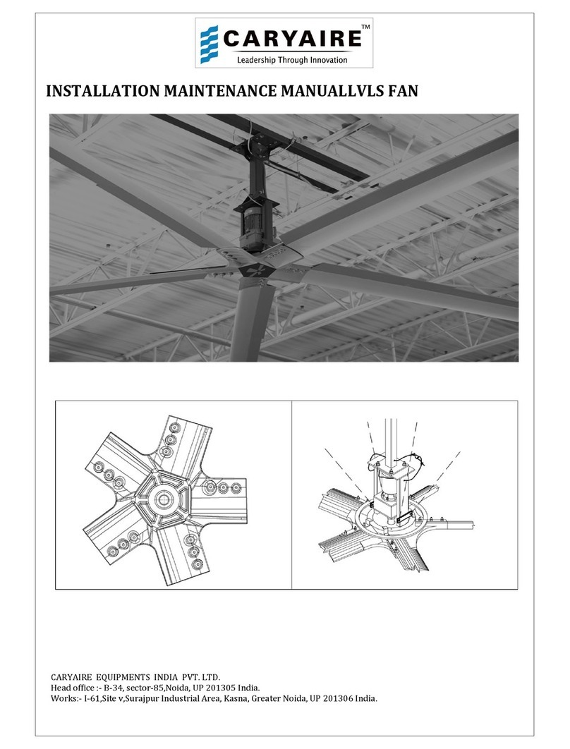
INSTALLATION MANUAL LVLS FAN
CARYAIRE EQUIPMENTS INDIA PVT. LTD.
Head office :- B-34 sector-
85 Noida UP 201305 India.
Works:- I-61 Site v Surajpur Industrial Area
Kasna Greater Noida UP 201306
INSTALLATION MANUAL LVLS FAN
CARYAIRE EQUIPMENTS INDIA PVT. LTD.
85 Noida UP 201305 India.
Kasna Greater Noida UP 201306
India.
INSTALLATION MANUAL LVLS FAN
85 Noida UP 201305 India.
LVLS FAN
Page 2 of 19
FIG-1
LVLS FAN
Page 3 of 19
CONTENTS
1) Table of Contents-------------------------------------------------
2) Important Information------------------------------------------
3) Pre-Installation Item Check List------------------------------
4) Technical details-------------------------------------------------
5) VFD Controller Installation------------------------------------
6) Different Mounting Arrangements---------------------------
7) Retaining/Safety Cable Installation--------------------------
8) Guy /Guide Wire Installation----------------------------------
9) Motor Wiring & Rotation Check-------------------------------
10) Blade Fixing-------------------------------------------------------
11) Trial Check--------------------------------------------------------
12) Fan Maintenance schedule------------------------------------
13) Packing List -----------------------------------------------------
03
04
05
06
07
08
12
13
14
15
16
16
18
LVLS FAN
Page 4 of 19
Important Information
Fan size in diameter 16 ft 20 ft 24 ft
4.9 m
6.1m
7.3m
Motor power
2HP 2HP 2HP
1.5 kW 1.5 kW 1.5 kW
Ampere at 400volt 3.55A 3.55A
3.55A
speed
73 rpm
63 rpm
5
6
rpm
Air flow (approx) 164 000 cfm 297 000 cfm 360 000 cfm
79 000 l/s 140 000 l/s 170 000 l/s
Maximum effective
diameter
36m 42m 50m
Weight 124 kg 132 kg 140 kg
Noise level
(measured 20ft horizontally from fan
center)
n/a n/a
Tools Req ired For Installation
•Level indicator
•Cable C tters(for stainless steel aircraft cables)
•Ratchet or Impact g n
•Basic Metric socket set
•Basic metric wrench set
•Lifting Device or Scaffolding
LVLS FAN
Page 5 of 19
Pre-Installation Item Check List
Hardware
1) VFD controller received is as per rated Voltage and Phase
2) Motor & gear Box assembly received are as per rated voltage & Phase
3) VFD controller is placed within the desired distance from the Fan
4) Check for any damage or loss during transit.
5) Has the Installation site been decided?
Installation site Clearances
6) Ensure that fan blades are a minimum 10ft or more from floor level.
7) Ensure that any obstructions are at least 2ft away horizontally from
the fan blade tip.
8) Ensure that Fan is installed so that minimum clearance from ceiling
is as per Table -1
Parts List:
9) Packing list of Fan parts & Hardware
10) Mounting Extension Kit (If ordered)
11) Installation Tools Kit
LVLS FAN
Page 6 of 19
FAN PLACEMENT & TECHNICAL DETAILS:
Placement of Fan is important in order to achieve optimal performance of the Fan.
Both Minimum horizontal and vertical clearances from the Fan are to be observed
strictly.
FIG-2
FIG-3
FIG-4
TABLE-1
FAN
DIAMETER
MOTOR
(KW. )
MOTOR
VOLTAGE
(V)
MOTOR
CURRENT
(AMPS.)
MOTOR
OUTPUT
RPM
MINIMUM
CLEARANCE
FROM CEILING
(mm.)
MINIMUM
HORIZONTAL
CLEARANCE FROM
BLADE TIP (mm. )
4.9 mt. 1.5 400 3.55 73 1500mm. 600 mm
6.1 mt. 1.5 400 3.55 63 1500 mm. 600 mm
7.3 mt. 1.5 400 3.55 56 1500 mm. 600 mm
VFD
INSTALLATION
VFD CONTROLLER :
[ MODEL SK 500E-151-340-
A]
Generally Electrical installation is done before
installing the Fan. Number of wires to be used
will depend on whether the VFD i
three phase. Wire Size should adhere to the
Local electrical codes. However connection
between VFD & Fan will need 4 wires. Whether
the Input to VFD is Single phase or three phase
power to the fan will always be three phase.
Type
Rated motor power:
Input voltage
Rated current:
Output voltage
Rated output current:
Output frequency
Enclosure:
Ambient temperature
Part number:
Dimensions (L1*B*T in [mm])
Approximate weight
Specifications:
LVLS FAN
A]
Generally Electrical installation is done before
installing the Fan. Number of wires to be used
will depend on whether the VFD i
s single or
three phase. Wire Size should adhere to the
Local electrical codes. However connection
between VFD & Fan will need 4 wires. Whether
the Input to VFD is Single phase or three phase
power to the fan will always be three phase.
SK 500E-151-340-A
1.5 kW
3AC 380…
480V
-
20%/+10%
47...63
5.6 A
3 AC 0
-
Mains voltage
4 A
0 Hz ...
400
Hz
IP20
0°C ... +40°C (S1)
275420150
Dimensions (L1*B*T in [mm])
226*74*153 mm
2 kg
•
four parameter sets selectable on
•Sensor less vector control
•
Automatic motor identification
•
5 Digital inputs 2 Analog inputs
•
2 Relay outputs 1 Analog output
•
Integrated brake chopper and dynamic
brake control
•RS232 and RS485 compati
bility via
RJ12 connector
LVLS FAN
Page 7 of 19
FIG-5
47...63
Hz
four parameter sets selectable on
-line
Automatic motor identification
5 Digital inputs 2 Analog inputs
2 Relay outputs 1 Analog output
Integrated brake chopper and dynamic
bility via
LVLS FAN
Page 8 of 19
Different mo ntig Applications :
Mounting applications shown below are representative only
CONCRETE BEAM MOUNT (FIG-6)
I BEAM MOUNTING (FIG-7)
LVLS FAN
Page 9 of 19
OWSJ MOUNTING (FIG-8)
PURLIN MOUNTING (FIG-9)
PIPE MOUNTING (FIG
STEP -2 STANDARD MOUNT
Following item
s are included in the
standard mount Kit.
•I-Beam Clamps
•
Spacers (requirement depends on
Support structure thickness)
•Mounting Plate
•Standard Mount
(300mm & 600mm)
•Safety Cables
•
Nuts & Bolts
LVLS FAN
PIPE MOUNTING (FIG
-10)
s are included in the
Spacers (requirement depends on
Support structure thickness)
FIG-11
LVLS FAN
Page 10 of 19
Installing the Standard Mount
•Insert the I-
Beam or the OWS
between the I-
Beam Clamps. Insert spacers if
needed.
•
Insert Nuts& Bolts and tighten properly
•
Place the safety cable as shown in the figure
•
Cable clamps are to be tightened as
shown.(fig-13)
•
Main safety cable should be inserted on the
saddle and the s
afety cable loop side has to
be on the U-
bolt side.(fig
STEP -3 EXTENSIONS
Following items are part of the Extension Kit
fig-15)
•
Extensions (Standard 600mm & 1200mm)
•Nuts Bolts & washers
•Safety Cables
Requirement of extension depends on place we have
to mount the fan . The length of extension along with
the standard
mount will determine the drop length of
the Fan. Custom length extension can be provided if a
non standard drop length is desired. We can use a
maximum of
two extensions per assembly.
LVLS FAN
Installing the Standard Mount
Beam or the OWS
J Beam
Beam Clamps. Insert spacers if
Insert Nuts& Bolts and tighten properly
Place the safety cable as shown in the figure
Cable clamps are to be tightened as
Main safety cable should be inserted on the
afety cable loop side has to
bolt side.(fig
-13)
FIG
FIG
Following items are part of the Extension Kit
(fig-14,
Extensions (Standard 600mm & 1200mm)
Requirement of extension depends on place we have
to mount the fan . The length of extension along with
mount will determine the drop length of
the Fan. Custom length extension can be provided if a
non standard drop length is desired. We can use a
two extensions per assembly.
FIG-14
LVLS FAN
Page 11 of 19
FIG
-12
FIG
-13
FIG-15
LVLS FAN
Page 12 of 19
Installing an Extension(fig-16 )
•Fasten top plate of extension to bottom plate
of standard mount using nuts bolts & washers
provided.
•Position the safety cables as per figure and fasten
the safety cable loops with the U-Clamps.
•For greater safety fasten two U-clamps at each loop
of the safety cable.
•Safety cables must always be used between fan
components. (Extensions Mounts Fan Frame etc.)
FIG-16
STEP-4 Main Hub & Drive Assembly(fig-17)
Following items form part of the
main Hub & Drive Assembly
•Hub
•Fan Frame
•Motor & Gear Box
•Trantorque nut
(All above parts are shipped assembled)
•Safety Cables
•Nuts Bolts & washers
FIG-17
Installing Main Hub & Drive Assembly
•Raise the Fan & align its mountig plate with
the bottom plate of standard mount or the
bottom plate of extension if used.
•Fasten the two plates using Nuts bolts &
•washers provided.
•Position the safety cables as per the figure
•and fasten safety cable loops using two
•U-Clamps on each safety cable loop.
•Verify fan level by checking both directions
•on the fan frame vertical post.
FIG-18
MOTOR HUB
ASSEMBLY
HUB
SAFETY CABLE
Fan f ame
Moto &
gea box
STEP -5
Guy Wires (Guide Rope)
•Guy Cables must
be fastened to the
Building structure at angles as
shown(FIG-20).
•
Guy Wires should be tight enough to
allow free self levelling and
be over tightened.
•
Main safety cable should be inserted on
the saddle side and the safety cable loop
side has to be on the U-
bolt side
Following items are included in the Kit
•Cable
•Cable Clamps
•Thimbles
•Eye Bolts
•
Nuts washers Bolts
FIG-20
LVLS FAN
Guy Wires (Guide Rope)
be fastened to the
Building structure at angles as
Guy Wires should be tight enough to
allow free self levelling and
should not
Main safety cable should be inserted on
the saddle side and the safety cable loop
bolt side
(FIG-13).
Following items are included in the Kit
FIG-19
LVLS FAN
Page 13 of 19
LVLS FAN
Page 14 of 19
LVLS FAN MOUNTING WITH EXTENSION FRAME
FIG-20A
LVLS FAN
Page 15 of 19
Installing G y Wires (G ide Ropes)
•First determine the location on ceiling to mount the Guy Wire so that it makes an
angle of 45-60(FIG-20)
•Install the Eye Bolt and tighten with Nuts & Bolts using washers(FIG- 21).
•Measure the cable required and cut keeping about 0.5 mt. extra. If the cable
requirement is more than 4mt. extra hardware is required .
•Secure one end with thimble and 2 cable clamps(FIG-22).
•Repeat the process for the other 3 Guy Ropes.
•Guy ropes should be about 90 degree apart(FIG- 19).
•Check the fan level by placing the level vertically on the fan frame. Adjust Guy
Ropes if required.
•Once levelled tighten hardware and again verify Fan level.
FIG-21
FIG-22
STEP -6: Connect Motor Terminal
Once the Fan Motor & Hub assembly are installed we may connect the motor terminal
leads to the electric supply
FIG-23
LVLS FAN
Page 16 of 19
STEP-7 : Check Motor Rotation
•Do not turn on the Power before double checking the Installation and electric
connections.
•Turn on Power and slowly increase frequency .
•Check the fan rotation . Observing from below fan rotation should be counter-
clockwise.
•If the fan rotates clockwise disconnect power supply and interchange output
leads.Fan should now rotate counter clockwise
•Disconnect Power supply and proceed to install fan blades.
STEP-8 : Blade Assembly
Blade kit includes the following Items
•Blades
•Blade Toppers
•Nuts Bolts & washers
FIG-24
STEP-9 : Safety Ring
•Safety Ring kit includes the
following items.
•Safety ring (5 Pieces)
•Bolts & washers
FIG-26
Installing Safety Ring
•Take two pieces of safety ring match the hole of one with the slot of the other.
tighten slightly the piece on appropriate place using bolts and washers.
•Continue as above till all pieces are installed. Now tighten all bolts
properly.Check level once again as per procedure mentioned Earlier
STEP-10 : F ll Start p
LVLS FAN
Page 17 of 19
•Activate Power to the Fan at power Distribution Board.
•Determine preferred speed for fan and set that speed.
General Notes on Operation:
•Avoid blocking areas where people will benefit from it. Move obstructios or
change orientation to get maximum advantage.
•Minimize interaction between path of fan blades and direction of local area
lighting.
•In summer it is advantageous to run the fan at the highest speed as it balances
comfort and work environments air speed tolerance. In winter maximum benefit
is achived by running the fan at a speed just below that which produces a
noticeable breeze.
FAN MAINTENANCE:
•Before carying out any maintenance cut power supply to fan and ensure no one
energizes the system while maintenance is going on.
•No maintenance is to be carried out on the Controller while the power supply is
on unless required for the job to be performed.
•A safety zone of 6mt. radius should be created while doing maintenance on the
fan safety wire and guy wires.
•Personal safety items are to be used by persons carrying maintenance work on
the fan.
•Risk assessment should be done before any maintenance work is carried out on
Fan Safety cables Guy wires etc.
•Before starting maintenance work a check list shall be prepared.
To ens re longevity of Caryaire HVAC fan, following checks need to be done
ann ally.
•Check torque of all mounting fasteners. Do not loosen or Re-Torque but check
torque in tightening direction with a calibrated torque wrench.
•Check gear motor for leaks.
•Check tightness of electrical leads of motor and controller
•Check if all safety cables are in place and also are not slack
•Remove dust accumulation to prevent fan from becoming unbalanced.
Maintenance Sched le: ( Motor & Gear Red cer)
LVLS FAN
Page 18 of 19
•Caryaire LVLS fan is driven by Nord Helical Gear reducer motors. These motors
are best suited for this application. These motors are known for precision
durability efficiency reliability and quiet operation.
Motor (First six-months)
•Check Hot Spots
•Tighten loose electric connections if any.
•Repeat every year.
Gear Red cer: (Yearly)
Check for any oil leakage. Plug leakage if any and top up oil.
Change oil after 10 000 hours of normal working.
Fan size Oil quantity
•4.9mt. 1.1 liters
•6.1mt & 7.3mt. 1.1 liters
•Recommended Lubricant: Mineral oil
Blades:
The blades are designed for maximum efficiency and quiet operation allowing
minimum air disruption directly below the fan.The airfoil blades are extruded
from 6063 aluminium alloy and heat treated to T-6 Temper condition. In
addition blades are also powder coated for corrosion resistence and ease of
cleaning.
Maintenance Sched le: ( First Six Months)
•Check tightness of Blades
•Ensure Blades are Level and Clean
•Repeat yearly.
Drop/ Mo nting:
The drop /mounting system helps prevent vibration or horizontal movement
from being transmitted to the building structure. Mounting system can be easily
installed in any building structure and allows Fan to hang level from the structure
beams.
Maintenance Sched le: ( First Six Months)
•Physical check of safety cables tightening of clamps if required.
•Physical check of Guy wires tightening of clamps if required.
•Check all nuts bolts & clamps.
LVLS FAN
Page 19 of 19
•Repeat yearly
Safety Check List:
•Disconnect all power at source before attempting Installation servicing or
cleaning.
•Installation to be done by certified electricians and contractors conversant with
local &
•national electric codes. If not complied by owners all warranty obligations of
Caryaire
•will stand Null & void.
•Wrong connection of Input and output terminals of controller will result in
damage to
•Controller. Faulty wiring is not covered by warranty.
•VFD parameters have been pre-set by manufacturer. These should not be altered
•without consulting the factory.
•All safety devices removed during maintenance should be re installed before
•applying power to the fan.
Packing List
CARYAIRE EQUIPMEN S
(I) PV . L D.
PACKING LIS OF
LVLS
FAN ( 16ft, 20ft, 24Ft )
SL.NO. I EM DE AILS Q Y. BOX NO.
Box Size (Wodeen box
with pallet)
1 Motor with Hub Assembly 1 no
1 750x750x730
2 Standard Extension Frame 1 no
3 Mounting Plate 1 no
4 VFD ( SK 500 E - 151 -340-A ) 1 no
5 Hardware Box 1 set
6 Alu.Blades 5 nos
2 3540x260x130

Other manuals for LVLS

1

Other Caryaire Fan manuals

Caryaire LVLS Manual

Caryaire

Caryaire LVLS Manual

Caryaire CKE Series Instruction manual

Caryaire

Caryaire CKE Series Instruction manual

Caryaire CZHW-40 User manual

Caryaire

Caryaire CZHW-40 User manual

Popular Fan manuals by other brands

Fancom I-fan 35 Xtra manual

Fancom

Fancom I-fan 35 Xtra manual

Revel AIR ALBANY Series instruction manual

Revel AIR

Revel AIR ALBANY Series instruction manual

Suntec Wellness Klimatronic CoolBreeze 2000 TV operating instructions

Suntec Wellness

Suntec Wellness Klimatronic CoolBreeze 2000 TV operating instructions

Progress Lighting AirPro P250065 installation manual

Progress Lighting

Progress Lighting AirPro P250065 installation manual

Omega OTEC ERVR Series Service manual

Omega

Omega OTEC ERVR Series Service manual

Suntec Wellness Klimatronic CoolBreeze 3000 TV manual

Suntec Wellness

Suntec Wellness Klimatronic CoolBreeze 3000 TV manual

Stadler Form charly floor operating instructions

Stadler Form

Stadler Form charly floor operating instructions

Bionaire BT17C Instruction leaflet

Bionaire

Bionaire BT17C Instruction leaflet

Vortice TIRACAMINO TC 10 M Instruction booklet

Vortice

Vortice TIRACAMINO TC 10 M Instruction booklet

Larson Electronics 970 CFM instruction manual

Larson Electronics

Larson Electronics 970 CFM instruction manual

Fanelite FANDC52LN USER MANUAL, INSTALLING AND OPERATING MANUAL

Fanelite

Fanelite FANDC52LN USER MANUAL, INSTALLING AND OPERATING MANUAL

Vortice TORRETTE TR E Instruction booklet

Vortice

Vortice TORRETTE TR E Instruction booklet

Craftmade UT56 installation guide

Craftmade

Craftmade UT56 installation guide

Pro-Elec PEL01924 instructions

Pro-Elec

Pro-Elec PEL01924 instructions

Faro Barcelona Thyphoon installation guide

Faro Barcelona

Faro Barcelona Thyphoon installation guide

Faro ALO installation guide

Faro

Faro ALO installation guide

Harbor Breeze Bath Ventilator with Light installation guide

Harbor Breeze

Harbor Breeze Bath Ventilator with Light installation guide

Westinghouse ETL-ES-VintageII-WH20 owner's manual

Westinghouse

Westinghouse ETL-ES-VintageII-WH20 owner's manual

manuals.online logo
manuals.online logoBrands
  • About & Mission
  • Contact us
  • Privacy Policy
  • Terms and Conditions

Copyright 2025 Manuals.Online. All Rights Reserved.