Case 4HK1-6HK1 User manual

SERVICE MANUAL
Revised 05-2006
Issued 02-2006
9-44061 NA
Replaces 9-44060 NA
4HK1-6HK1
ISUZU ENGINES

9-44061 NA4HK1- 6HK1 ISUZU ENGINES
05-2006Revision 1
9-44060 NA4HK1- 6HK1 ISUZU ENGINES02-2006First Edition
REVISION HISTORY
RemarksIssue Issue Date Applicable Machines
Any use of editorial or pictorial content is strictly prohibited without express written permission from
CNH America, LLC. Racine, WI 53403 U.S.A..
CNH America, LLC reserves the right to make improvements in design or changes in specifications at any time without incurring any
obligation to install them on units previously sold.
All data given in this publication is subject to production variations. Dimensions and weights are only approximate. Illustrations do not
necessarily show products in standard condition.For exact information about any particular product, please consult your Dealer
Find manuals at https://best-manuals.com

1
9-44061Issued 02-06
INDEX OF CHAPTERS
GENERAL INFORMATION .................................................................................................................................... 0A
ENGINE MECHANICAL ......................................................................................................................................... 1A
COOLING SYSTEM ............................................................................................................................................... 1B
FUEL SYSTEM....................................................................................................................................................... 1C
ENGINE ELECTRICAL........................................................................................................................................... 1D
EXHAUST SYSTEM AND TURBOCHARGER........................................................................................................1F
NOTE: CNH Company reserves the right to make changes in the specification and design of the machine with-
out prior notice and without incurring any obligation to modify units previously sold.
The description of the models shown in this manual has been made in accordance with the technical specifica-
tions known as of the date of design of this document.
Find manuals at https://best-manuals.com

IN-2 Introduction
UNITS OF MEASURE
This manual adopts the units of measure based on International System.
The MKSA system units of measure are indicated within brackets after the units of measure of the International
System.
Example: 24.5 MPa (250 kgf/cm2)
The following table converts the International System units of measure in some of the main units belonging to other
system.
Quantity To convert
from (IS)
Into
(Others) Multiply by Quantity To convert
from (IS)
Into
(Others) Multiply by
Lenght mm in 0.03937 Pressure MPa kgf/cm210.197
mm ft 0.003281 MPa psi 145.0
Volume
L US gal 0.2642 Power kW CV-PS 1.360
L US qt 1.057 kW HP 1.341
m3yd31.308 Temperature °C °F °C x 1.8 + 32
Mass kg lb 2.205 Speed km/h mph 0.6214
Force N kgf 0.10197 min-1 rpm 1.0
N lbf 0.2248 Capacity L/min US gpm 0.2642
Torqu e N.m kgf.m 0.10197 mL/rev cc/rev 1.0
N.m lbf.ft 0.7375
Find manuals at https://best-manuals.com

General Information 0A-1
GENERAL INFORMATION
General Information
Contents
General Information . . . . . . . . . . . . . . . . . . . . . . . 0A-2
Service Precautions . . . . . . . . . . . . . . . . . . . . . . 0A-2
Reading the model . . . . . . . . . . . . . . . . . . . . . . . 0A-6
General information . . . . . . . . . . . . . . . . . . . . . . 0A-7
Find manuals at https://best-manuals.com

0A-2 General Information
General Information
Service Precautions
In order to carry out work safely
1. Always use an engine stand when taking the
engine down from the vehicle.
Do not place the engine directly onto the ground,
or place in a manner that interferes with the oil
pan.
2. If you are working together with others, always pay
attention to each other's safety.
3. If you are repairing any part of the electrical
system, always remove the minus side cable from
the battery terminal before starting work. If you are
removing the battery cover, always remove the
cover in a place that is away from sources of fire/
heat.
4. Do not perform painting work or leave the engine
running for long periods of time in an enclosed or
badly ventilated indoor workshop.
5. Always use the correct specialized tool indicated in
the instructions. Using the incorrect tool may
cause damage to the parts or injury to the person
using the tool.
6. All regular tools, gauges and special tools should
be regularly inspected, and prepared before
starting work. Do not use bent spanners, hammers
with damaged edges, chipped chisels, or any other
faulty or damaged tools.
7. Always pay close attention to safety and handling
requirements when using grinders, cranes,
welders, and other such equipment.
Moreover, always wear the correct protective
garments and use the necessary safety tools for
the job in hand.
Find manuals at https://best-manuals.com

General Information 0A-3
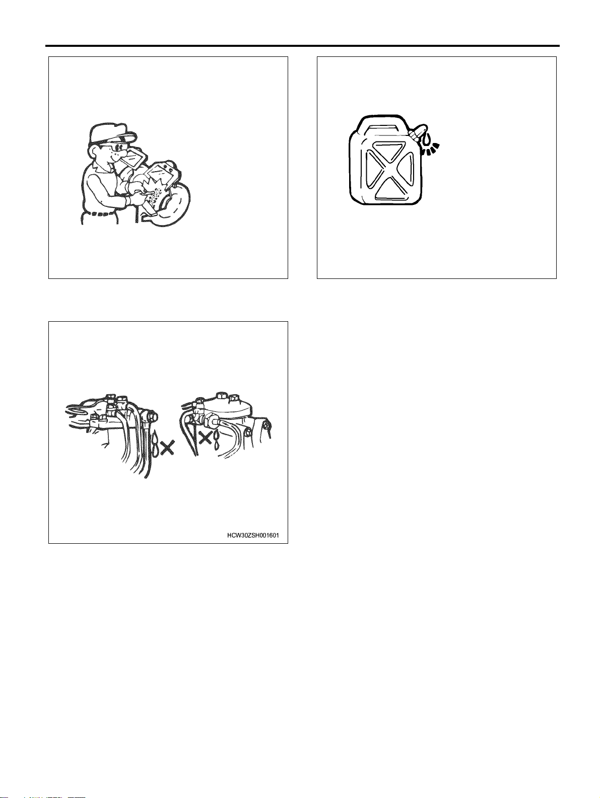
8. Always check that there are no fuel leaks when
performing maintenance work on the fuel system.
(It may cause a fire.)
9. Pay close attention to the risk of ignition if you are
handling parts that carry a high voltage.
Furthermore, any oil or fat spilt onto rubber parts
must be wiped off immediately, as it will cause
deterioration of the rubber.
Replacement parts and part numbers.
1. Always replace packing, oil seals, o-rings, caulking
lock nuts, folding lock plates, split pins and other
such parts with brand new parts.
2. The parts numbers contained in this manual may
not represent the supply condition of the parts, and
the part numbers may be changed due to
revisions. Therefore, parts should always be
checked against a parts catalogue before use.
Liquid gasket
1. Each time you disassemble parts that use liquid
gasket, completely remove the old gasket residue
from each of the parts and matching sections using
a scraper, then clean each of the parts to
completely remove oil, water, and dirt etc. from the
various surfaces. Using the specified type of liquid
gasket, apply new liquid gasket to each of the
surfaces before reassembling the parts.
2. In order to make it easier to clean liquid gasket
surfaces, apply gasket remover liquid (Pando-
391D made by Three Bond Co., Ltd.) and leave
the part to stand for approximately 10 minutes,
after which the old liquid gasket residue will be
easier to remove.
However, this should not be used on resin
components or painted components.
3. Please take care not to apply too much or too little
liquid gasket.
Also, you should always re-apply the liquid gasket
upon itself when you start and finish application.
4. Make sure that there are no gaps when re-
installing the liquid gasket parts to each other. If
there are gaps between the two parts, re-apply the
liquid gasket. Some parts, especially the oil pan,
use the same size studs as a guide to eliminate the
need for knock pin positioning etc.
5. Re-install these parts within 7 minutes of applying
the liquid gasket.
Find manuals at https://best-manuals.com

0A-4 General Information
If more than 7 minutes passes, remove the
previous liquid gasket and re-apply it.
6. Please wait for at least 30 minutes since the last
part is installed before starting the engine.
Liquid gasket
• Always use the liquid gasket products listed above,
or a liquid gasket identical to the ones listed above.
• Use the correct quantity of liquid gasket. Always
follow the handling instructions for each product.
Application procedure
1. Wipe the contact surfaces clean of all water, fat or
oil. The contact surfaces should be dry.
2. Apply a regular bead width of liquid gasket to one
of the contact surfaces. Make sure that the bead
does not break at this point.
Notes:
If there are special regulations concerning the
application procedure in the repair document, please
follow those regulations.
Work procedure
1. Wipe the joint surfaces of the bolt, bolt hole, and
screw thread section clean of water, fat, and oil.
The contact surfaces should be dry.
2. Apply Loctite to the top 1/3 of the screw.
3. Tighten the bolt to the correct tightening torque.
Important:
After tightening the bolt, do not apply excessive torque
or try to rotate the bolt until at least one hour has
passed, and the Loctite has hardened.
Procedure for using the Plastiguage
Example: Procedure for measuring the clearance
between the connecting rod bearing and crank pin.
• Clean the connecting rod and bearing, and install
the bearing to the rod.
• Cut the plastiguage to the same width as the crank
pin, and while avoiding the oil pore of the crank pin
lay the gauge parallel to the pin.
Seal section Product name Manufacturer's name
Between cylinder block and – Flywheel housing 1207B Three Bond
Between cylinder block and – Flywheel housing and –
Crankcase 1207B Three Bond
Between cylinder block and – Crank case 1207B Three Bond
Between cylinder block and – Front cover 1207B Three Bond
Cylinder block, head plug nipple, unit, switches 262 Loctite
Type Measurable range mm (in)
PG-1 (Green) 0.025 – 0.076 (0.001 – 0.003)
PR-1 (Red) 0.051 – 0.152 (0.002 – 0.006)
PB-1 (Blue) 0.102 – 0.229 (0.004 – 0.009)
Find manuals at https://best-manuals.com

General Information 0A-5
• Line up the marks on the connecting rod and cap
and install the crank pin, apply molybdenum
disulphide to the thread section and bearing
surface of the fastening bolt, and rotate both cap
and bolt to the correct torque.
Important:
Do not move the connecting rod while using the
plastiguage.
• Gently remove the cap and connecting rod, and
measure the crushed width of the plastiguage
(clearance between rod and pin) using the scale
printed on the bag.
Example: Measuring the clearance between the crank
bearing and crank journal
• Clean the clamp face of the cylinder block and
crankcase bearing, and also the bearing, and
install the cylinder block to the crankcase.
• Gently rest the crankshaft on the cylinder block,
and rotate it approximately 30 degree to stabilize it.
• Cut the plastiguage to the same size as the journal
width, and while avoiding the oil pore of the journal
lay the gauge parallel to the journal.
• Gently rest the crank case on the cylinder block,
apply molybdenum disulphide to the thread section
and bearing surface of the fastening bolt, and
tighten in sequence to the correct torque.
Important:
Do not rotate the crankshaft while using the
plastiguage.
• Gently remove the crankcase, and measure the
crushed width of the plastiguage (clearance
between bearing and journal) using the scale
printed on the bag.
Find manuals at https://best-manuals.com

0A-6 General Information
Reading the model
Engine number stamping position
4HK1
WSHK0185

General Information 0A-7
6HK1
General information
Terminology, description of abbreviations
Terminology definitions
WSHK0186
Term Explanation
Maintenance standard The generic name for reference values required for maintenance, such as nominal
dimension, selection of a reference point, and limit.
Nominal dimension Shows the standard value at the point of manufacture that does not include the
common difference.
Selection of a reference point Shows the standard value after assembling, repairing, or adjusting.
Limit When this value (dimensions) is reached, it shows that the part has reached its full
limit and must be replaced or repaired.
Front ⋅rear, left ⋅right, upper ⋅
lower
These show each orientations of parts installed to the vehicle when looking from
the vehicle's forward direction.
Unit Units written to SI conventions (mainly torque, pressure, force)
[Example] Length: mm, Torque: N⋅m {kgf⋅m}
Warning Items that carry the warning mark pose a danger to life or threat of serious injury if
not strictly observed.
Caution Items that carry the caution mark may cause injury or lead to accidents if not strictly
observed.
Important Items that carry the important mark may cause the vehicle to break down, or may
prevent the guaranteed normal operation of the system or related parts if not strictly
observed.

0A-8 General Information
Description of abbreviations
Notes Items that should receive special mention within a work procedure.
Term Explanation
Abbreviation Description
AC Alternating Current
Alternating Current
ACC Accessory
Accessory
ACG Alternating Current Generator
Alternating current generator
API American Petrol Institute
American Petroleum Institute
ASM (Assy) Assembly
Assembly
ATDC After Top Dead Center
After Top Dead Center
BAT, BATT Battery
Battery
BRG, Brg Bearing
Bearing
BKT, BRKT Bracket
Bracket
BTDC Before Top Dead Center
Before Top Dead Center
CO Carbon Oxide
Carbon Monoxide
CONN Connector
Connector
CPU Central Processing Unit
Central processing unit
C/U Control Unit
Control unit
DC Direct Current
Direct current
DI Direct Injection
Direct injection
ECU Engine Control Unit / Electronic Control
Unit
Engine control unit / control unit
ECM Engine Control Module
Engine control module
EGR Exhaust Gas Recirculation
Exhaust gas recirculation
Exh, EXH Exhaust
Exhaust
Ft, FRT Front
Front
FWD Forward
Forward
F/C Fuel Cut
Fuel Cut
GND Ground
Earth
IC Integrated Circuit
Integrated circuit
ID Plate Identification plate
Identification plate, ID plate
IN Intake, Intake
Intake
ISO International Organization for
Standardization
International Organization for
Standardization
I/PUMP Injection Pump
Injection Pump
JIS Japanese Industrial Standard
Japanese Industrial Standard
L/H, LH Left Hand
Left hand side
M/V Magnetic Valve
Magnetic valve
NOx Nitrogen Oxide
Nitrogen Oxide
N-TDC Number - Top Dead Center
Top dead center rotational frequency
OPT Option
Option
PPole(S)
Pole
PCV Pump Control Valve/ Positive
Crankcase Ventilation
Pump control valve/ Positive crankcase
ventilation
PM Particulate Matter
Particulate matter
PS Pre-Stroke
Pre-stroke
PTO Power Take Off
Power take off
QOS Quick On System
Rapid preheating system
Rr, RR Rear
Rear
Abbreviation Description

General Information 0A-9
SI (International System of Units)
With regards the conversion to SI (International
System of Units)
The introduction of the SI systems aims to
internationally unify the metric system and the various
units used by different countries (traditional weights
and measures, the foot pound method etc.), and to
curb the confusion that occurs between the different
units (conversion calculations etc.).
The new calculating method which adopted SI units
was completely adopted in Japan in 1992, and is
standardized by JIS-Z-8203.
All of the units in this manual are written in line with the
International System of Units SI units, and conventional
units are written in { } brackets.
SI
French) Abbreviated name of Le Systeme International
d’Unites
Connection between main SI units and conventional units
*1 Published service data may conveniently use kg for
force and mass (weight) instead of kgf.
*2 Some conversion results may be rounded off to 1 or
2 decimal places.
Converting expressions of quantity
When converting, prefixes such as k (kilo) or m (mili)
are used.
• 200 kgf/cm2 = 19,620 kPa = 19.6 MPa
• 40 mmHg = 5,332 Pa = 5.3 kPa
R/H, RH Right Hand
Right hand side
R/L Relay
Relay
STD Standard
Standard
SW Switch
Switch
TICS Timing & Injection rate Control System
A type of injection system
VGS Turbo Variable Geometry turbocharger
System
Adjustable turbo, VGS turbo
W/L Warning Lamp
Warning lamp
Abbreviation Description
SI Conventional Unit Item, unit conversion
Length m m Same as the conventional unit
Weight (Mass) kg kg Same as the conventional unit
Force N * kg, kgf 1 kgf = 9.80665 N
Torque N⋅m*kg⋅m, gf⋅m1kgf⋅m = 9.80665 N⋅m
Pressure Pa *kg/cm2, mmHg 1 kgf/cm2 = 9.80665 kPa, 1 mmHg = 133.3 Pa
Dynamic force, horsepower W PS 1 PS = 0.74 kW
Capacity, air volume displacement m3Litle, L, cc 1 Litle = 1 dm3, 1 cc = 1mLitle = 1cm3
Fuel consumption g/(kW⋅h) g/(PS⋅h) 1 g/(PS⋅h) = 1.360 g/(kW⋅h)
MMega10
61,000,000
kKilo10
31,000
hHecto10
2100
dDeci10
-1 0.1
c Centi 10-2 0.01
m Milli 10-3 0.001
µMicro 10-6 0.000001

0A-10 General Information
Table of standard Isuzu tightening torque
The tightening torque values in the table below apply to
all situations unless a special tightening torque is
specified.
Isuzu standard bolts, nuts
The * mark indicates where soft materials have been used for internal thread sections, such as castings.
N⋅m {kgf⋅m}
Strength
classification
4.8
4T 7T
Bolt head
section shape Hexagon head bolt Flange bolt Hexagon head bolt Flange bolt
*M10× 1.5 19.6 ~ 33.3 {2.0 ~ 3.4} 22.3 ~ 37.2 {2.3 ~ 3.8} 27.5 ~ 45.1 {2.8 ~ 4.6} 30.3 ~ 50.4 {3.1 ~ 5.1}
M12 × 1.25 49.0 ~ 73.5 {5.0 ~ 7.5} 54.9 ~ 82.3 {5.6 ~ 8.4} 60.8 ~ 91.2 {6.2 ~ 9.3} 68.1 ~ 102.1 {6.9 ~
10.4}
*M12× 1.75 45.1 ~ 68.6 {4.6 ~ 7.0} 51.0 ~ 76.5 {5.2 ~ 7.8} 56.9 ~ 84.3 {5.8 ~ 8.6} 62.7 ~ 94.0 {6.4 ~ 9.6}
M14 × 1.5 76.5 ~ 114.7 {7.8 ~
11.7}
83.0 ~ 124.5 {8.5 ~
12.7}
93.2 ~ 139.3 {9.5 ~
14.2}
100.8 ~ 151.1 {10.3 ~
15.4}
*M14× 271.6 ~ 106.9 {7.3 ~
10.9}
77.2 ~ 115.8 {7.9 ~
11.8}
88.3 ~ 131.4 {9.0 ~
13.4}
94.9 ~ 142.3 {9.7 ~
14.5}
M16 × 1.5 104.0 ~ 157.0 {10.6 ~
16.0}
115.6 ~ 173.3 {11.8 ~
17.7}
135.3 ~ 204.0 {13.8 ~
20.8}
150.1 ~ 225.2 {15.3 ~
23.0}
*M16× 2100.0 ~ 149.1 {10.2 ~
15.2}
109.4 ~ 164.2 {11.2 ~
16.7}
129.4 ~ 194.2 {13.2 ~
19.8}
142.5 ~ 213.8 {14.5 ~
21.8}
M18 × 1.5 151.0 ~ 225.6 {15.4 ~
23.0} —195.2 ~ 293.2 {19.9 ~
29.9} —
*M18× 2.5 151.0 ~ 225.6 {15.4 ~
23.0} —196.1 ~ 294.2 {20.0 ~
30.0} —
M20 × 1.5 206.0 – 310.0 {21.0 ~
31.6} —269.7 ~ 405.0 {27.5 ~
41.3} —
*M20× 2.5 190.2 ~ 286.4 {19.4 –
29.2} —249.1 ~ 374.6 {25.4 ~
38.2} —
M22 × 1.5 251.1 – 413.8 {25.6 ~
42.2} —362.8 ~ 544.3 {37.0 ~
55.5} —
*M22× 2.5 217.7 ~ 327.5 {22.2 ~
33.4} —338.3 ~ 507.0 {34.5 ~
51.7} —
M24 × 2358.9 ~ 539.4 {36.6 ~
55.0} —430.5 ~ 711.0 {43.9 ~
72.5} —
*M24× 3338.3 ~ 507.0 {34.5 ~
51.7} —406.0 ~ 608.0 {41.4 ~
62.0} —

General Information 0A-11
The * mark indicates where soft materials have been used for internal thread sections, such as castings.
N⋅m {kgf⋅m}
Strength classification 8.8 9.8
9T
Bolt head section
shape Hexagon head bolt Flange bolt Hexagon head bolt Flange bolt
M6 × 15.6 ~ 11.2 {0.6 ~
1.1}
6.6 ~ 12.2 {0.6 ~
1.2} ——
M8 × 1.25 13.4 ~ 25.7 {1.4 ~
2.6}
15.3 ~ 28.4 {1.6 ~
2.9}
16.7 ~ 30.4 {1.7 ~
3.1}
18.1 ~ 33.6 {1.9 ~
3.4}
M10 × 1.25 31.3 ~ 52.5 {3.2 ~
5.4}
35.4 ~ 58.9 {3.6 ~
6.1}
37.3 ~ 62.8 {3.8 ~
6.4}
42.3 ~ 70.5 {4.3 ~
7.2}
*M10× 1.5 31.3 ~ 51.4 {3.2 ~
5.2}
34.5 ~ 57.5 {3.5 ~
5.8}
36.3 ~ 59.8 {3.7 ~
6.1}
40.1 ~ 66.9 {4.1 ~
6.8}
M12 × 1.25 69.3 ~ 104.0 {7.1 ~
10.6}
77.7 ~ 116.5 {7.9 ~
11.9}
75.5 ~ 113.8 {7.7 ~
11.6}
85.0 ~ 127.5 {8.7 ~
13.0}
*M12× 1.75 64.8 ~ 96.1 {6.6 ~
9.8}
71.4 ~ 107.2 {7.3 ~
10.9}
71.6 ~ 106.9 {7.3 ~
10.9}
79.5 ~ 119.2 {8.1 ~
12.2}
M14 × 1.5 106.2 ~ 158.8 {10.8
~ 16.2}
114.9 ~ 172.3 {11.7
~ 17.6}
113.8 ~ 170.6 {11.6
~ 17.4}
123.4 ~ 185.1 {12.6
~ 18.9}
*M14× 2100.6 ~ 149.8 {10.3
~ 15.3}
108.2 ~ 162.2 {11.1
~ 16.6}
106.9 ~ 160.0 {10.9
~ 16.3}
115.5 ~ 173.3 {11.8
~ 17.7}
M16 × 1.5 154.3 ~ 232.5 {15.7
~ 23.7}
171.1 ~ 256.7 {17.4
~ 26.2}
160.0 ~ 240.3 {16.3
~ 24.5}
176.9 ~ 265.3 {18.0
~ 27.1}
*M16× 2147.6 ~ 221.4 {15.0
~ 22.6}
162.5 ~ 243.8 {16.6
~ 24.9}
153.0 ~ 229.5 {15.6
~ 23.4}
168.5 ~ 252.7 {17.2
~ 25.8}
M18 × 1.5 222.5 ~ 334.3 {22.7
~ 34.1} —229.5 ~ 345.2 {23.4
~ 35.2} —
*M18× 2.5 223.6 ~ 335.4 {22.8
~ 34.2} —230.5 ~ 346.2 {23.6
~ 35.3} —
M20 × 1.5 307.4 ~ 461.7 {31.4
~ 47.1} —316.8 ~ 475.6 {32.3
~ 48.5} —
*M20× 2.5 284.0 ~ 472.1 {29.0
~ 43.5} —293.2 ~ 440.3 {29.2
~ 44.9} —
M22 × 1.5 413.6 ~ 620.5 {42.2
~ 63.3} —424.6 ~ 636.5 {43.3
~ 64.9} —
*M22× 2.5 385.7 ~ 578.0 {39.3
~ 58.9} —394.2 ~ 592.3 {40.0
~ 60.4} —
M24 × 2490.8 ~ 810.5 {50.0
~ 82.7} —554.1 ~ 830.6 {56.5
~ 84.7} —
*M24× 3462.8 ~ 693.1 {47.2
~ 70.7} —520.7 ~ 781.6 {53.1
~ 79.7} —

0A-12 General Information
Designations for Isuzu standard bolt heads
Legend
1. Hexagon head bolt(4.8, 4T)
2. Hexagon head bolt(4.8, 4T)
3. Flange bolt(4.8, 4T)
4. Flange bolt(4.8, 4T)
5. Hexagon head bolt(7T)
6. Flange bolt(7T)
7. Hexagon head bolt (refined 8.8)
8. Hexagon head bolt (refined 8.8)
9. Hexagon head bolt(Un-refined 8.8)
10. Hexagon head bolt(Un-refined 8.8)
11. Flange bolt(8.8)
12. Flange bolt(8.8)
13. Hexagon head bolt(9.8, 9T)
14. Hexagon head bolt(9.8, 9T)
15. Flange bolt(9.8, 9T)
16. Flange bolt(9.8, 9T)
Flare nut
Pipe diameter tightening torque
(for medium and large
size vehicles)
Flare nut 2 side width (mm)
Old New
Flare nut tightening torque (service
standard value) N⋅m {kgf⋅m}
φ4.76 mm 12.8 ~ 18.6 {1.3 ~ 1.9} 14 14
φ6.35 mm 23.5 ~ 49 {2.4 ~ 5.0} 17 17
φ8.0 mm 23.5 ~ 49 {2.4 ~ 5.0} 19 17
φ10.0 mm 44.1 ~ 93.2 {4.5 ~ 9.5} 22 19
φ12.0 mm 58.8 ~ 137.3 {6.0 ~ 14.0} 27 24
φ15.0 mm 78.5 ~ 156.9 {8.0 ~ 16.0} 30 30

General Information 0A-13
Taper screw from connectors (brass)
N⋅m {kgf⋅m}
Screw size PT(R) 1/8 PT(R) 1/4 PT(R) 3/8 PT(R) 1/12
— 2.0 ~ 14.7
(0.2 ~ 1.5)
4.9 ~ 15.7
(0.5 ~ 1.6)
9.8 ~ 16.7
(1.0 ~ 1.7)
9.8 ~ 17.7
(1.0 ~ 1.8)

ENGINE MECHANICAL (4HK1, 6HK1) 1A-1
ENGINE
ENGINE MECHANICAL (4HK1, 6HK1)
TABLE OF CONTENTS
ISUZU DIESEL ENGINE (4HK1, 6HK1) . . . . . . .1A-3
Precautions on Service Work . . . . . . . . . . . . . . 1A-3
Main Data and Specifications . . . . . . . . . . . . . 1A-11
Cylinder Head Cover . . . . . . . . . . . . . . . . . . . . . 1A-14
Components. . . . . . . . . . . . . . . . . . . . . . . . . . . 1A-14
Removal . . . . . . . . . . . . . . . . . . . . . . . . . . . . . 1A-15
Installation . . . . . . . . . . . . . . . . . . . . . . . . . . . . 1A-16
Torque Specifications . . . . . . . . . . . . . . . . . . . 1A-18
Inlet Cover . . . . . . . . . . . . . . . . . . . . . . . . . . . . . 1A-20
Components . . . . . . . . . . . . . . . . . . . . . . . . . . 1A-20
Removal . . . . . . . . . . . . . . . . . . . . . . . . . . . . . 1A-21
Installation . . . . . . . . . . . . . . . . . . . . . . . . . . . . 1A-22
Torque Specifications . . . . . . . . . . . . . . . . . . . 1A-24
Turbocharger and Exhaust Manifold . . . . . . . . . 1A-25
Components . . . . . . . . . . . . . . . . . . . . . . . . . . 1A-25
Removal . . . . . . . . . . . . . . . . . . . . . . . . . . . . . 1A-26
Inspection . . . . . . . . . . . . . . . . . . . . . . . . . . . . 1A-27
Installation . . . . . . . . . . . . . . . . . . . . . . . . . . . . 1A-28
Torque Specifications . . . . . . . . . . . . . . . . . . . 1A-32
Timing Gear Train . . . . . . . . . . . . . . . . . . . . . . . 1A-35
Components . . . . . . . . . . . . . . . . . . . . . . . . . . 1A-35
Removal . . . . . . . . . . . . . . . . . . . . . . . . . . . . . 1A-36
Inspection . . . . . . . . . . . . . . . . . . . . . . . . . . . . 1A-38
Installation . . . . . . . . . . . . . . . . . . . . . . . . . . . . 1A-40
Torque Specifications . . . . . . . . . . . . . . . . . . . 1A-51
Special Tool . . . . . . . . . . . . . . . . . . . . . . . . . . . 1A-52
Rocker Arm Shaft ASM . . . . . . . . . . . . . . . . . . . . 1A-53
Components . . . . . . . . . . . . . . . . . . . . . . . . . . 1A-53
Removal . . . . . . . . . . . . . . . . . . . . . . . . . . . . . 1A-53
Disassembly . . . . . . . . . . . . . . . . . . . . . . . . . . 1A-54
Reassembly . . . . . . . . . . . . . . . . . . . . . . . . . . 1A-56
Installation . . . . . . . . . . . . . . . . . . . . . . . . . . . . 1A-57
Torque Specifications . . . . . . . . . . . . . . . . . . . . 1A-59
Camshaft ASM . . . . . . . . . . . . . . . . . . . . . . . . . . 1A-60
Components. . . . . . . . . . . . . . . . . . . . . . . . . . . 1A-60
Removal . . . . . . . . . . . . . . . . . . . . . . . . . . . . . 1A-61
Disassembly . . . . . . . . . . . . . . . . . . . . . . . . . . 1A-62
Reassembly . . . . . . . . . . . . . . . . . . . . . . . . . . . 1A-64
Fixing torque . . . . . . . . . . . . . . . . . . . . . . . . . . 1A-66
Special Tool . . . . . . . . . . . . . . . . . . . . . . . . . . . 1A-66
Installation . . . . . . . . . . . . . . . . . . . . . . . . . . . . 1A-67
Torque Specifications . . . . . . . . . . . . . . . . . . . 1A-69
Valve Stem Seal, Valve Spring . . . . . . . . . . . . . . 1A-70
Components . . . . . . . . . . . . . . . . . . . . . . . . . . 1A-70
Removal . . . . . . . . . . . . . . . . . . . . . . . . . . . . . 1A-70
Inspection . . . . . . . . . . . . . . . . . . . . . . . . . . . . 1A-71
Installation . . . . . . . . . . . . . . . . . . . . . . . . . . . . 1A-72
Special Tool . . . . . . . . . . . . . . . . . . . . . . . . . . . 1A-74
Cylinder Head . . . . . . . . . . . . . . . . . . . . . . . . . . 1A-75
Components . . . . . . . . . . . . . . . . . . . . . . . . . . 1A-75
Removal . . . . . . . . . . . . . . . . . . . . . . . . . . . . . 1A-75
Disassembly . . . . . . . . . . . . . . . . . . . . . . . . . . 1A-79
Inspection . . . . . . . . . . . . . . . . . . . . . . . . . . . .1A-82
Reassembly . . . . . . . . . . . . . . . . . . . . . . . . . . 1A-88
Installation . . . . . . . . . . . . . . . . . . . . . . . . . . . .1A-94
Torque Specifications . . . . . . . . . . . . . . . . . . 1A-101
Special Tool . . . . . . . . . . . . . . . . . . . . . . . . . . 1A-101
Piston, Connecting Rod . . . . . . . . . . . . . . . . . . 1A-103
Components . . . . . . . . . . . . . . . . . . . . . . . . . 1A-103
Removal . . . . . . . . . . . . . . . . . . . . . . . . . . . . 1A-103
Disassembly . . . . . . . . . . . . . . . . . . . . . . . . . 1A-104
Reassembly . . . . . . . . . . . . . . . . . . . . . . . . . 1A-110
Installation . . . . . . . . . . . . . . . . . . . . . . . . . . . 1A-112
Torque Specifications . . . . . . . . . . . . . . . . . . 1A-114
Special Tool . . . . . . . . . . . . . . . . . . . . . . . . . . 1A-114
Flywheel . . . . . . . . . . . . . . . . . . . . . . . . . . . . . . 1A-115
Components . . . . . . . . . . . . . . . . . . . . . . . . . 1A-115
Removal . . . . . . . . . . . . . . . . . . . . . . . . . . . . 1A-115
Inspection . . . . . . . . . . . . . . . . . . . . . . . . . . . 1A-117
Installation . . . . . . . . . . . . . . . . . . . . . . . . . . . 1A-117
Torque Specifications . . . . . . . . . . . . . . . . . . 1A-119
Special Tool . . . . . . . . . . . . . . . . . . . . . . . . . . 1A-119
Front Cover . . . . . . . . . . . . . . . . . . . . . . . . . . . 1A-120
Components . . . . . . . . . . . . . . . . . . . . . . . . . 1A-120
Removal . . . . . . . . . . . . . . . . . . . . . . . . . . . . 1A-121
Installation . . . . . . . . . . . . . . . . . . . . . . . . . . .1A-122
Torque Specifications . . . . . . . . . . . . . . . . . . 1A-124
Crankshaft Front Oil Seal . . . . . . . . . . . . . . . . . 1A-126
Components . . . . . . . . . . . . . . . . . . . . . . . . . 1A-126
Removal . . . . . . . . . . . . . . . . . . . . . . . . . . . . 1A-126
Installation . . . . . . . . . . . . . . . . . . . . . . . . . . .1A-128
Torque Specifications . . . . . . . . . . . . . . . . . . 1A-133
Special Tool . . . . . . . . . . . . . . . . . . . . . . . . . . 1A-133
Crankshaft Rear Oil Seal . . . . . . . . . . . . . . . . . 1A-134
Components . . . . . . . . . . . . . . . . . . . . . . . . . 1A-134
Removal . . . . . . . . . . . . . . . . . . . . . . . . . . . . 1A-134
Installation . . . . . . . . . . . . . . . . . . . . . . . . . . .1A-135
Special Tool . . . . . . . . . . . . . . . . . . . . . . . . . . 1A-138
Crankshaft . . . . . . . . . . . . . . . . . . . . . . . . . . . . 1A-139
Components . . . . . . . . . . . . . . . . . . . . . . . . . 1A-139
Removal . . . . . . . . . . . . . . . . . . . . . . . . . . . . 1A-139
Disassembly. . . . . . . . . . . . . . . . . . . . . . . . . . 1A-141
Reassembly . . . . . . . . . . . . . . . . . . . . . . . . . 1A-141
Inspection . . . . . . . . . . . . . . . . . . . . . . . . . . .1A-141
Installation . . . . . . . . . . . . . . . . . . . . . . . . . . .1A-146
Torque Specifications . . . . . . . . . . . . . . . . . . 1A-150
Special Tool . . . . . . . . . . . . . . . . . . . . . . . . . . 1A-150
Cylinder Block . . . . . . . . . . . . . . . . . . . . . . . . . 1A-152
Components . . . . . . . . . . . . . . . . . . . . . . . . . 1A-152
Removal . . . . . . . . . . . . . . . . . . . . . . . . . . . . 1A-152
Inspection . . . . . . . . . . . . . . . . . . . . . . . . . . .1A-153
Installation . . . . . . . . . . . . . . . . . . . . . . . . . . .1A-154
Lubrication System . . . . . . . . . . . . . . . . . . . . . . 1A-157
Precautions on Service Work . . . . . . . . . . . . 1A-157

1A-2 ENGINE MECHANICAL (4HK1, 6HK1)
Function Check . . . . . . . . . . . . . . . . . . . . . . . 1A-158
Special Tool . . . . . . . . . . . . . . . . . . . . . . . . . .1A-159
Oil Port Cover ASM . . . . . . . . . . . . . . . . . . . . . 1A-160
Components . . . . . . . . . . . . . . . . . . . . . . . . . 1A-160
Removal . . . . . . . . . . . . . . . . . . . . . . . . . . . . 1A-160
Installation . . . . . . . . . . . . . . . . . . . . . . . . . . .1A-160
Oil Cooler . . . . . . . . . . . . . . . . . . . . . . . . . . . . . 1A-162
Components. . . . . . . . . . . . . . . . . . . . . . . . . . 1A-162
Removal . . . . . . . . . . . . . . . . . . . . . . . . . . . . 1A-163
Disassembly . . . . . . . . . . . . . . . . . . . . . . . . . 1A-164
Reassembly . . . . . . . . . . . . . . . . . . . . . . . . . 1A-164
Installation . . . . . . . . . . . . . . . . . . . . . . . . . . .1A-165
Oil Pan . . . . . . . . . . . . . . . . . . . . . . . . . . . . . . .1A-168
Components . . . . . . . . . . . . . . . . . . . . . . . . . 1A-168
Removal . . . . . . . . . . . . . . . . . . . . . . . . . . . . .1A-168
Installation . . . . . . . . . . . . . . . . . . . . . . . . . . .1A-169
Oil Pump . . . . . . . . . . . . . . . . . . . . . . . . . . . . .1A-171
Components . . . . . . . . . . . . . . . . . . . . . . . . . 1A-171
Removal . . . . . . . . . . . . . . . . . . . . . . . . . . . . .1A-171
Disassembly . . . . . . . . . . . . . . . . . . . . . . . . . 1A-172
Reassembly . . . . . . . . . . . . . . . . . . . . . . . . . . 1A-172
Inspection . . . . . . . . . . . . . . . . . . . . . . . . . . .1A-173
Installation . . . . . . . . . . . . . . . . . . . . . . . . . . .1A-174
Oil Pressure Switch. . . . . . . . . . . . . . . . . . . . . . 1A-178
Inspection . . . . . . . . . . . . . . . . . . . . . . . . . . .1A-178
Table of contents
Other Case Engine manuals
Popular Engine manuals by other brands

Lister Petter
Lister Petter alpha Series Operator's handbook

d2itsu
d2itsu FCSD 1V EC FLEX Series Installation and maintenance manual

SOMFY
SOMFY RAINER MAESTRIA 50 RTS Quick programming guide

Yanmar
Yanmar 6LYA-UTE Service manual

HPI Racing
HPI Racing Fuelie 26S instruction manual

JetCat
JetCat P60 instruction manual