3,
MowerBladeBolts:
Beforeoperatingthemowerforthe
firsttime,checktheboltsholdingthe
blades.THEYMUSTBETIGHT.After
thefirst8 hoursoperating,checkthem
again.Wheneverthebladesarere-
moved,itisa goodpracticetoinstall
newlockwashersunderthebolts,and
againchecktightnessafternext8 hours
operation,
4.
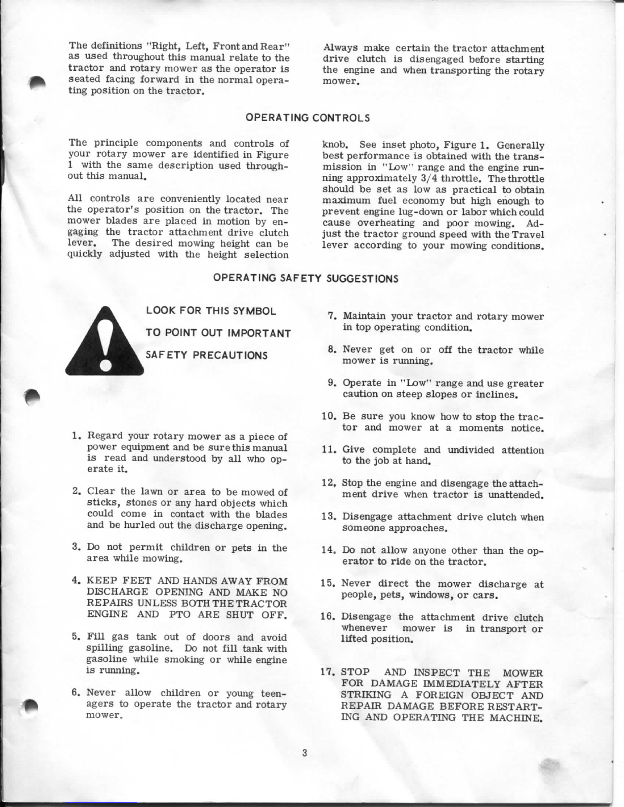
EngineMaintenance:
Completetractorandenginemain-
tenanceinstructionsareoutlinedon
page12and13ofyourtractorOpe-
rator'sManual,Whenmowing,give
particularattentiontotheareaswhich
areaffectedbygrassaccumulation.
Checkandbrushofftheengineair
intakescreenandheatexchangerfins
DAILY.Alsocheckandcleanthe
engineaircleanerelementdailyas
explainedonpage21ofyourtractor
manual.Ifmowingunderparticularly
dryordusyconditionsa "Precleaner,"
partnumberK0237421,isavailable
throughyourJ I CaseDealerwhich
fitsovertheregularelement.See
Figure6,Thisprecleanercanbe
washedoutwithsoapandwaterasnec-
essarywhichwillextendthelifeofthe
dryelementfurnishedwiththetractor.
Figure6.
5.
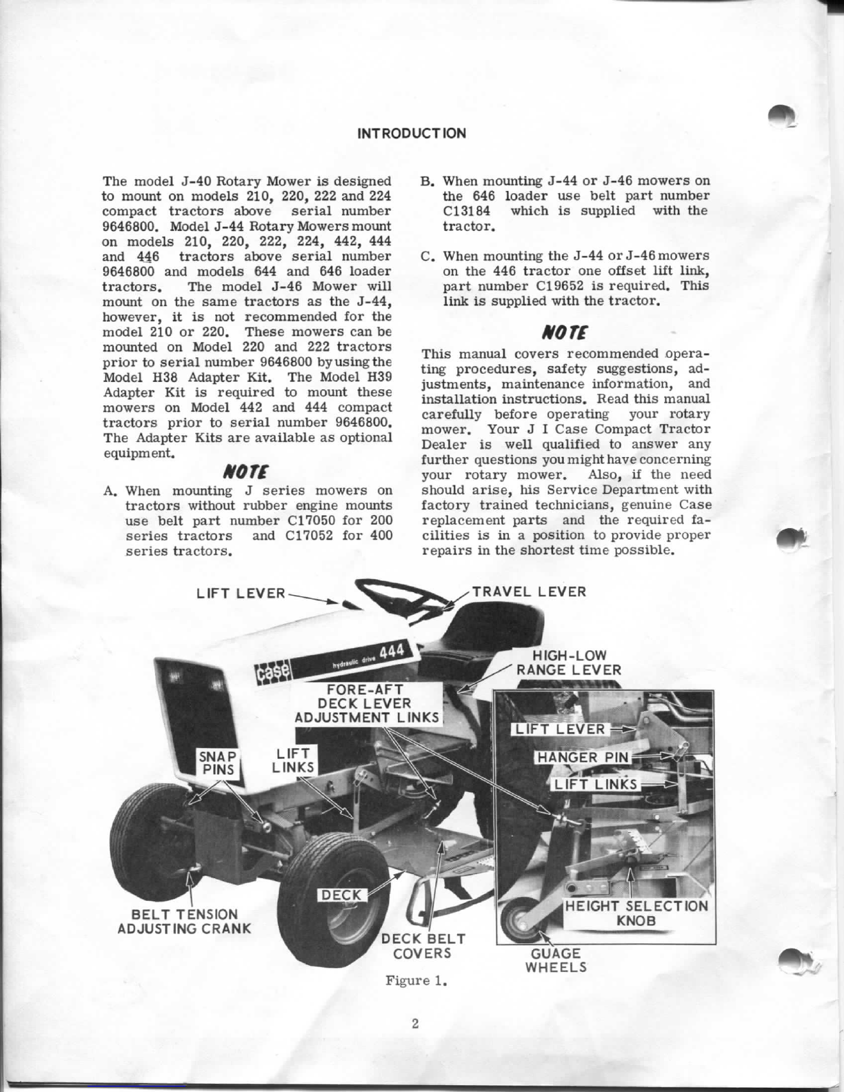
MowerFore-AftLevelingLinks:See
Figure7,
Theselinksareadjustedatthefactory
forcorrectmowerdecklevel.Clean
cuttingandminimumhorsepowercon-
sumptionaredependentuponthemower
beinglevel,foreandaft.Ifreadjust-
mentshouldbecomenecessary,locate
thetractorandmowerona levelsur-
faceandplacetheHeightSelectorLever
inthe2-1/2"settingbeforemaking
adjustments.Toraisethefrontof
themower,firstloosentheouternut
oneachlinkandthenequallyturnthe
innernutsrearward.Tolowerthefront
ofthemower,loosentheinnernuton
eachlinkandturntheouternutsfore-
ward.Checkbladeheightsasclose
tothefrontandrearedgesofthemower
aspossible.Distancebetweenthe
bladesandthelevelsurfaceshouldbe
thesameatbothfrontandrearedges
ofmower,
6,MowerSideToSideLeveling:See
Figure7,
Mowersidetosidelevelingisad-
justedatthefactory.However,should
readjustmentbecomenecessaryitmay
bedonebylooseningthetwocarriage
boltsontherighthandsidethatsecure
thegaugewheelcarriertothedeck.
Theholesmaybeslottedifadditional
adjustmentisrequired.Afterob-
taininga levelposition,retightenthe
carriagebolts.
7,
MowerGaugeWheels:SeeFigure7,
Removethegaugewheelsaftereach
10hoursofmowingandluricatethe
bushingsandaxleboltswithchassis
grease.
Asanalternatetogrease,the
wheelscanbeoiledeachfourhours
ofoperation.Makesuretheoil
penetratestotheinsideofthe
bushingsbyholdingthedeckat
aslantedanglewhilelubricating.
Figure7.
-sr.
6