Case J40 User manual

ROTARYMOWER
J40,
J44,J46
Operator'sManualNo.9-50552
JI Case
ATennecoCompany
JENNECO
casecoltingersoll.com

INTRODUCTION
Thismanualcontainsrecommendedoperatingprocedures,
safetyrules,adjustments,maintenanceinformation,assem-
blyandmountinginstructions.Readthismanualcarefully
beforeoperatingyourrotarymower.
YourJ I CaseCompactTractorDealeriswellqualifiedto
answeranyfurtherquestionsyoumighthaveconcerning
yourrotarymower.Also,iftheneedshouldarise,his
ServiceDepartmentwithfactorytrainedtechnicians.
genuineCasereplacementpartsandtherequiredfacilities
isinthepositiontoprovideproperrepairsintheshortest
timepossible.
Thedefinitions"Right,Left,Front,andRear"asused
throughoutthismanualrelatetothetractorandrotary
mowerastheoperatorisseatedfacingforwardinthe
normaloperatingpositionofthetractor.
MOWERAPPLICATIONCHART
MOWERMODEL RECOMMENDEDTRACTORMODEL
J-40
J-44
J-46
210,
220,222
222,
224,444,446,644,646
224,
444,446,644,646
BELTAPPLICATIONCHART
TRACTORMODEL
210All
220PriortoS/N9656747
220S/N9656747andafter
222PRIORTOS/N9658189
222S/N9658189andafter
224All
442All
444PriortoS/N9661261
444S/N9661261andafter
446All
644PriortoS/N9698343
644S/N9698343andafter
646All
BELTPARTNUMBER
18708
17050
18708
17050
18708
18708
17052
17052
18709
18709
17052
C21931
013184
Beltshippedwithloadertractor
SPECIALINFORMATION
TRACTORMODEL
446All C19652specialoffsetlift
linksuppliedwithtractor
FORINSTALLATIONON
PRIORMODELTRACTORS
TRACTORMODEL USEKIT
220,
222priortoS/N9646800
442,
444priortoS/N9646800 H-38
H-39
3
casecoltingersoll.com

SAFETYRULES
A
Thissafetyalertsymbolindicatesimportantsafetymessagesinthis
manual.
Whenyouseethissymbol,carefullyreadthemessagethat
followsandbealerttothepossibilityofpersonalinjuryordeath.
A
Regardyourrotarymowerasa
pieceofpowerequipmentandbe
surethismanualisreadandunder-
stoodbyallwhooperateit.
A
CAUTION:
Fillgastankoutof
doorsandavoidspillinggasoline.
Donotfilltankwithgasolinewhile
smokingorwhileengineisrunning.
Maintainyourtractorandrotary
mowerintopoperatingcondition.
CAUTION:
Neverallowchildren
^^^L oryoungteenagerstooperatethe
^^V^^^tractorandrotarymower.
A
CAUTION:
Clearthelawnorarea
tobemowedofsticks,stonesorany
hardobjectswhichcouldcomein
contactwiththebladesandbe
hurledoutthedischargeopening.
CAUTION:
Nevergetonoroff
^ftthetractorwhilethemoweris
A
CAUTION:
Donotpermitchildren
orpetsintheareawhilemowing
andneverdirectthemowerdis-
chargeatbuildings,people,pets,
windowsorcars.
CAUTION:
OperateinLowrange
^anduseextremecautiononslopes
^^L^^^
orinclines.Alwaysbackup,and
^^m^^^
drivedownslopes.Mowinthe
forwardanddowndirectiononly.
WARNING:Keepfeetandhands
A
awayfromdischargeopeningand
makenorepairsunlessboththe
tractorengineandattachmentdrive
areshutoffandthekeyisremoved
fromthetractor.
ACAUTION:
Besureyouknowhow
tostopthetractorandmowerata
momentsnotice.
casecoltingersoll.com

A
CAUTION:
Givecompleteandun-
dividedattentiontothejobathand.
A
CAUTION:
Disengageattachment
drivelever,stopengineandremove
keyandsparkplugwire(s)before
makingadjustments.
A
CAUTION:
Stopengine,disengage
attachmentdrive,setparkingbrake
andremovekeywhentractoris
unattended.
CAUTION:
Unbalancedbladesare
A
ahazardandwillcausepremature
wearandfailureofbearingsand
spindles.Ifthebladescannotbe
balancedbyresharpening,replace
themwithnewones.
A
CAUTION:
Donotallowanyone
otherthantheoperatortorideon
thetractor.
ACAUTION:
Shutoffengine,allow
enginetocoolandremovekeyand
sparkplugwire(s)beforereplacing
mowerdrivebelt.
CAUTION:
Disengageattachment
driveclutchwhensomeone
^^ft^^kapproachesorwheneverthemower
^^^^^^^isintransportortheliftedposition.
A
CAUTION:
SpinningBlade- Keep
handsandfeetfromunderthe
mowerdecktopreventinjury.
A
CAUTION:
Stopandinspectthe
mowerfordamageimmediatelyaf-
terstrikinga foreignobjectand
repairdamagebeforerestartingand
operatingthemachine.
WARNING:Besurethattheat-
A
tachmentdriveclutchisoff,the
engineisshutoff,thekeyremoved
andthebladeshavestopped
spin-
ningbeforeattemptingtocleana
pluggeddischargechute.
5
casecoltingersoll.com

OPERATINGCONTROLS
Theprinciplecomponentsandcontrolsofyourrotary
mowerareidentifiedinFigure1 withthesamedescription
usedthroughoutthismanual.
Allcontrolsarelocatedneartheoperator'spositiononthe
tractor.Themowerbladesareplacedinmotionbyen-
gagingtheattachmentdriveclutchlever.Thedesired
mowingheightcanbeadjustedwiththeheightselection
lever.
Generallybestperformanceisobtainedwiththetransmis-
sioninLowrangeandtheenginerunning% tofullthrottle.
Thethrottleshouldbesetaslowaspracticaltoobtain
maximumfueleconomybuthighenoughtopreventengine
lugdownorlaborwhichcouldcauseoverheatingandpoor
mowing.
Adjustthetractorgroundspeed withthetravel
leveraccordingtoyourmowingconditions.
TRACTORTRAVELLEVER
FIGURE1 MODEL446WITHMODELJ-4648"ROTARYMOWER
OPERATION
1.
Keepmowerbladessharpandbalancedascoveredin
theMaintenanceSectionofthismanual.
2.
Operateengineatapproximately% tofullthrottleand
regulatethegroundspeedTravelLeveraccordingto
mowingconditions.Asa generalrule,setthethrottle
aslowaspracticaltoobtainmaximumfueleconomy
buthighenoughtoavoidenginelugdownorlabor
whichcouldcauseoverheatingandpoormowingper-
formance.Unlessgrassisunusuallylight,always
operatein"Low"speed range.
3.Ifgrassisheavyandhigherthannormal,resultscanbe
improvedbymowingtwice.Makethefirstcutwiththe 6
mowersethigherthannormal;thenrepeatwiththe
mowersetatdesiredfinishedcutheight.Whenmowing
heavygrass,alwaysdischargeclippingsawayfromthe
uncutarea.
WARNING:Besurethattheat-
tachmentdriveclutchisoff,the
engineisshutoff,thekeyremoved
^^^^^^andthebladeshavestopped
spin-
^^K^^Bningbeforeattemptingtocleana
pluggeddischargechute.
casecoltingersoll.com

4.
Figures2 and3 illustratetwosystemsformowing.If
thegrassishighorheavy,alwaysmowtothrowthe
clippingsawayfromtheuncutarea.Figure2.Ifthe
grassislightandmorethoroughmulchingisdesired,
dischargetheclippingstowardthecenteroftheuncut
area.
Figure3.Whenmowinginthismanner, a final
stripofmulchedclippingsaboutthreetofourfeetwide
willremainnearthecenterofthelawn.Thiscanbe
easilyrakeduptoleavea wellgroomedappearance.
FIGURE3
5.Trimmingwillbeneaterandcloserbyusingtheright
sideofthemowersincetheclippingswillbedischarged
awayfromtheobject.Alsothesafetyshieldoverthe
dischargeopeningpreventsmowingasclosetoobjects.
CAUTION:
Nevergetonoroff
thetractorwhilethemoweris
6.Donotsteponthemowerdeckwhengettingonoroff
thetractor.Ifmountingthetractorfromtherightside,
placeyourrightfootontherightfootrest,yourright
handonsteeringwheelandlefthandontheseatback
andstepontothetractor,swingingyourleftfoot
throughbetweenthesteeringwheelandseat.
Whenmountingfromtheleftside,startwithyourleft
footontheleftfootrest,yourlefthandonsteering
wheelandrighthandonseatbackandstepontotractor
swingingyourrightfootthroughbetweensteering
wheelandseat.Dismountthetractorusingthereverse
oftheaboveprocedures.
7.Themechanicalorhydraulicliftleverisusedtoraise
themowerintotransportandtoloweritintocutting
position.
A slightpullingpressureonthemechanical
leverwillpermitthereleasebuttontobemoreeasily
depressed.
Lowerthehydraulicliftuntiltheliftarmsare
posi-
tionedmidwayintheliftlinkslots.Thiswillallowthe
mowerdeckandgaugewheelstofollowthecontourof
theground.Donotplacethehydraulicliftcontrol
leverinthehydraulicfloatpositionwhenmowing.
TheHeightSelectionsettingsareexplainedinthe
adjustmentssectionofthismanual.
8.Alwaysengagetractorandmowerdrivesystems
smoothly.
A
Becertainwhoeveroperatesthe
mowerhasreadandunderstands
theSafetyRulesinthefrontofthis
manual.
7
casecoltingersoll.com

ADJUSTMENTS
CAUTION:
Disengageattachment
drivelever,stopengine
and
remove
keys
and
sparkplugwire{s)before
makingadjustments.
1.
HeightSelectionLever.
See
Figure
4.
Themowercuttingheight
is
adjustablefrom
V/j"
to
3%" inV2"
increments.
Tochangecuttingheight:
a.
Raisemowerintotransportposition
to
relieve
weightfrom
the
heightselectionlever.
b.Pulloutward
onthe
heightselectionknob.
c.Move
the
lever
upor
down
tothe
desiredheight.
d.
Pushknobinto
the
holeselected.
2.
GaugeWheels.
See
Figure
4.
Alwaysoperate
the
mowerwith
the
gauge wheels
on
theground
and
all
weight
offthe
mowerliftlinks
to
obtain
a
level
and
uniform
cut.Be
sure
the
gauge
wheelsclear
the
groundwhentransporting
the
mower.
GAUGEWHEEL
FIGURE
4
ADJUSTMENTS
3.DriveBeltTension.
See
Figure
5.
Themowerdrivebelt
is
propertytensionedwhen
the
frontidlerspring
has1/8
inch(approximately
the
thickness
oftwo
nickels)gapsbetween
its
coils.
IMPORTANTCheck
and
adjust
the
tension
onanew
beltafter
the
first
20
minutes
andthe
nexthour
of
mowingsince
itis
normal
for
a
belt
to
stretchslightlyduring
its
initialrun-inperiod.
Toincrease
the
belttension,turn
the
adjustingcrank
in
acounterclockwisedirectionwhilefacing
the
front
of
thetractor.
Todecrease
the
belttension
orto
install
or
remove
the
belt,turn
the
adjustingcrankclockwise.
DECK
DRIVE
PULLEY
1
WIND
KEV
CLOCKWISE
BV
HAND
ASFARA!
POSSIBLE
AND
PLACE
ATTACHMENTDRIVE
IN
ENCAGEMEM POSITION
JiINSTALL BELTOVER
PULLEYS
AND
IDLER
PULLEYS
AS
SHOWN
DOUBLECHECKTHATTHE
BELT
IS
PROPERLYSEAT-
ED
IN
EACHPULLEYWITH
ONLY
ONEK
DECREE
I*IST
BETWEENSUCCEED-
INGPULLEYS
J
WIND
KEV
COUNTER.
CLOCKWISE
UNTIL
SPRING
SHOWS
t.'fl
INCH
GAPBE
IWEEN
COILSAS
VIEWED
FROMTHESIDE
THE1*0
IDLER
PULLEYS
SHOULD
BE
APPRO"
EVEN
OB
CLOSE
TO
A
COMMON
CtNTER
LINE
*
AT
PERIODIC
INTERVALS
RECHECK
FOR\ft
INCH
CLEARANCEBETWEEN
COILS
AND
ADJUST
AS
REQUIRED
FIGURE
5
8
casecoltingersoll.com

4.
MowerFore-AftLevelingLinks.SeeFigure6.
Cleancuttingandminimumhorsepowerconsumption
aredependentuponthemowerbeinglevelforeandaft.
Toadjust,locatethetractorandmowerona level
surfacesuchasyourgaragefloorandplacetheHeight
Selectionleverinthe272"setting.Lowerthemower
intothecuttingposition.
Toraisethefrontofthemower,firstloosentherear
nutoneachlinkandthenequallyturnthefrontnuts
rearward.
Tolowerthefrontofthemower,loosenthefrontnut
ofeachlinkandturntherearnutsforward.
Positionbladessothattheyareparalleltothetractor
frame(foreandaftline)beforemeasuringclearance.
Checkbladeheightsasclosetothefrontandrearedges
ofthemowerbladesaspossible.Besuretotighten
bothfrontandrearnutswhencheckingbladeheight.
Adjustthelevelinglinksuntilthedistancebetweenthe
bladetipsandthelevelsurfaceisthesameatboththe
frontandrearofthemower.Theforwardtipmaybe
slightlylowerthantherearwardtip.Neverpermitthe
rearwardtiptobelowerthantheforwardtip.{This
doublespowerconsumptioninmowing)!
5.MowerSidetoSideLeveling.SeeFigure6.
Mowersidetosidelevelingisadjustedatthefactory.
Shouldreadjustmentbecomenecessary,itmaybedone
bylooseningthetwocarriageboltsontherighthand
sidethatsecuresthegaugewheelcarriertothedeck.
Theholesmaybeslottedifadditionaladjustmentis
required.
Afterobtaininga levelposition,retighten
thecarriagebolts.
Sidetosidelevelingshouldbedoneona levelsurface,
suchasyourgaragefloorwiththeheightselectionlever
inthe2^^" settingandthemowerloweredintothe
cuttingposition.Besurethemowerislevelforeand
aftbeforecheckingsidetosidelevel.
TWOCARRIAGEBOLTS
FIGURE6 ADJUSTMENTS
9
casecoltingersoll.com

MAINTENANCE
CAUTION:
Disengageattachment
^^ drivelever,stopengineandremove
keysandsparkplugwire(s)before
^^^^H^^
makingadjustments.
1.
MowerBladeBolts.SeeFigure7.
Beforeoperatingthemowerforthefirsttime,check
theboltsholdingtheblades.Theymustbetight.After
thefirst8 hoursofoperation,checkthemagain.When-
everthebladesareremoved,itisgoodpracticetoinstall
newlockwashersunderthebolts,andagaincheck
tightnessafterthenext8 hoursofoperation.
2.
BentBlades.SeeFigure7.
Checkforbentbladesbeforemountingthemowerand
afterimpact.Bladetipsshouldbewithin% inchofthe
samehorizontalplane.Alignallsixbladetips,twoata
timeasshowninFigure7 todeterminethis.Mowing
withbentbladeswillcausemissedstripsanda poor
mowingjob.Bentbladesshouldbereplaced
immediately.
MOWERBLADEBOLTS
TIPSSHOULDBEWITHIN
%"OFSAMEHORIZONTAL
PLANE.
FIGURE7
3.MowerGaugeWheels.SeeFigure8.
Removethegaugewheelsaftereach10hoursofmow-
ingandlubricatethebushingsandaxleboltswith
chassisgrease.Asanalternatetogrease,thewheels
canbeoiledaftereachfourhoursofoperation.Make
suretheoilpenetratestotheinsideofthebushingsby
holdingthedeckatananglewhilelubricating.
4.
Mowerdeckbeltreplacement.SeeFigure8.
Thedeckbeltisautomaticallytensionedbya spring
loadedidlerpulleyanddoesnotrequireadjustment.
Installa newbeltinthefollowingmanner:
a.
Removethedeckbeltguard.
b.Relaxtheidlerpulleytensionbypivotingittowards
thefrontofthedeckwitha 9/16"boxwrench
placedonthehexnut.
c.Removetheoldbelt.
d.
Placethenewbeltaroundthe3 spindlepulleysand
idler.
e.Rotatesystembyhandtocheckforfreeoperation
andidlertakeup.
f.Replacedeckbeltguard.
HEXNUT
casecoltingersoll.com

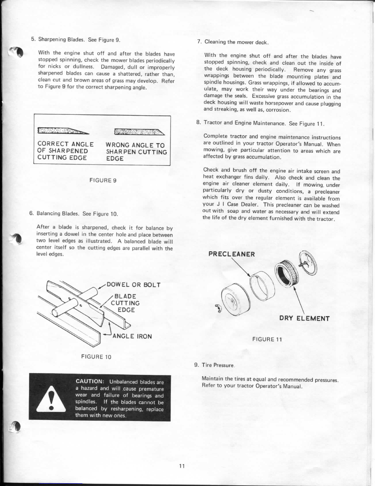
5.SharpeningBlades.SeeFigure9. 7.Cleaningthemowerdeck.
Withtheengineshutoffandafterthebladeshave
stoppedspinning,checkthemowerbladesperiodically
fornicksordullness.Damaged,dullorimproperly
sharpenedbladescancausea shattered,ratherthan,
cleancutandbrownareasofgrassmaydevelop.Refer
toFigure9 forthecorrectsharpeningangle.
CORRECTANGLEWRONGANGLETO
OFSHARPENEDSHARPENCUTTING
CUTTINGEDGEEDGE
FIGURE9
6.BalancingBlades.SeeFigure10.
Aftera bladeissharpened,checkitforbalanceby
insertinga dowelinthecenterholeandplacebetween
twoleveledgesasillustrated.A balancedbladewill
centeritselfsothecuttingedgesareparallelwiththe
leveledges.
FIGURE10
CAUTION:
Unbalancedbladesare
A
ahazardandwillcausepremature
wearandfailureofbearingsand
spindles.Ifthebladescannotbe
balancedbyresharpening,replace
themwithnewones.
It
Withtheengineshutoffandafterthebladeshave
stoppedspinning,checkandcleanouttheinsideof
thedeckhousingperiodically.Removeanygrass
wrappingsbetweentheblademountingplatesand
spindlehousings.Grasswrappings,ifallowedtoaccum-
ulate,
mayworktheirwayunderthebearingsand
damagetheseals.Excessivegrassaccumulationinthe
deckhousingwillwastehorsepowerandcauseplugging
andstreaking,aswellas,corrosion.
8.TractorandEngineMaintenance.SeeFigure11.
Completetractorandenginemaintenanceinstructions
areoutlinedinyourtractorOperator'sManual.When
mowing,
giveparticularattentiontoareaswhichare
affectedbygrassaccumulation.
Checkandbrushofftheengineairintakescreenand
heatexchangerfinsdaily.Alsocheckandcleanthe
engineaircleanerelementdaily.Ifmowing,under
particularlydryordustyconditions,a precleaner
whichfitsovertheregularelementisavailablefrom
yourJ \e Dealer.Thisprecleanercanbewashed
outwithsoapandwaterasnecessaryandwillextend
thelifeofthedryelementfurnishedwiththetractor.
FIGURE11
9.TirePressure
Maintainthetiresatequalandrecommendedpressures.
RefertoyourtractorOperator'sManual.
casecoltingersoll.com

INSTALLATION
I.ASSEMBLY
1.
Beforeassemblingthemower,layoutandcheckthe
individualcomponents.SeeFigure12.
TheJ-40Mowerisshippedwithonedrivebeltandone
setofliftlinkssinceitisintendedforuseonlow
clearance(200series)tractorsonly.
TheJ-44andJ-46Mowersareshippedwithtwodrive
beltsandtwosetsofliftlinkssincetheymaybe
mountedoneitherloworhighclearance{200,400or
600series)tractors.
2.
Selecttheappropriatebeltusingapplicationcharton
page3.Thebeltpartnumberisstampedintothe
outercoveringofthebelt.Selectthetwoshortlift
linksifinstallationistobeona lowclearance(200or
600series)tractor.
Selectthetwolongliftlinksiftheinstallationistobe
ona Model444.
SelectonelongliftlinkandspeciallinkP/NC 19652
(suppliedwithtractor)iftheinstallationistobeona
Model446.
FIGURE12MODELJ-46ROTARYMOTOR- DISASSEMBLED
3.Assembletheliftlinkstothemountingbracketand
securewithcotterkeysasshowninFigure13.
ThespeciallinkP/NC 19652fortheModel446
(suppliedwithtractor)shouldbeinstalledontheright
handside.
Theslottedendofthelinkswillbeconnectedtothe
tractorlifearmswhenmounted.
NOTEDonotpreassemblethemountingbracket
tothemowerdeckasshowninFigure13.
Itiseasiertoinstallthemountingbracket
tothetractorfirstandthenattachthemower
decktoit.
12
casecoltingersoll.com

II.
MOUNTING
1.
Locatetractorona levelsurface.Checktiresforequal
andrecommendedpressuresasfoundinyourtractor
Operator'sManual.
2.
Beforeattachingthemountingbracket,turnthe
adjustingcrankcounterclockwiseasfaraspossibleto
providemountingclearanceatthefrontaxle.Referto
Figure14.
ADJUSTINGCRANK
FIGURE14BELTADJUSTMENT
13
casecoltingersoll.com

3.Position
the
mountingbracketunderthefront
ofthe
tractorandontotheanchorpinsasshown
in
Figure
15.
Raisethefront
of
thebracketandreleasethesnapfast
pins
to
lock
in
place.
NOTEModel644and646
-
Themountingbracket
isattachedwith
thetwo
clevispins
and
safetypinsconnected
to
eachfrontside
of
theframe.
4.
Lower
the
liftarmsfully.Positiontheliftlinksonthe
inside
ofthe
liftarms.
Puta
plainwasher
on
each
clevis
pinand
install
inthe
fronthole
of
theliftarm
from
the
inside.Secure
the
linkswiththesafetypins
attheoutside.Refer
to
Figure
15.
5.Raisetheliftarmsintothetransportposition.
SNAPFASTPIN
FIGURE
15
MOUNTINGTHEJ-46MOWERMOUNTINGBRACKET
6.Place
the
heightselectionlever
inthe
V/a"setting
to
gainadditionalclearanceandslidethemowerunderthe
tractorfromtherightliandsideandalignthedeckwith
theattachingholes
inthe
mountingbracket.Lower
themountingbracket
tothe
mowerdeck.Refer
to
Figure
16.
7.Install
the
Fore-Aftlevelinglinks
tothe
mounting
bracketasillustrated
in
Figure
16.
9.With
the
engineshut
off,key
removed,
and
cool
to
thetouch,engage
the
attachmentdrivelever.Raise
thehoodandremovethesparkplugwire(s)
for
safety.
Insert
the
drivebelt
in
front
ofthe
idlerpulleys,
be-
tween
thefanand
heatexchanger
and
onto
the
attachmentdriveclutchpulley.Turn
the
adjusting
crankclockwiseuntil
the
belt
canbe
easilyplaced
around
the
idlerpulleys
and
onto
the
mowerdrive
pulley.
8.Connectthemountingbrackettothetabsonthemower
deckwiththeclevispinsandsafetypinsprovided.
NOTELiftingthemowerdeckupwardslightlywill
aid
in
aligningtheholesbetweenthemount-
ingbracketanddecktabs.
CAUTION:
Shut
off
engine,allow
engine
to
coolandremovekeyand
^^^^^L
sparkplugwire(s)beforereplacing
^^^^fljjjft
mowerdrivebelt.
14
casecoltingersoll.com

r
10.
Checktomakesurethebeltisproperlylocatedineach
pulley.Turntheadjustingcrankcounterclockwiseto
tensionthebeltuntiltheidlerspringcoilsopen1/8
inch(approximatelythethicknessoftwonickels.See
Figure5 and14.)Disengagetheattachmentdrivelever
andreconnectthesparkplugwire(s).
IMPORTANTBeforeoperatingthemower,reviewand
followtherecommendationsoutlined
intheadjustmentsandMaintenance-
sectionofthismanual.
TheJ I CaseCompanyreservesthe
righttomakeimprovementsin
designchangesinspecificationsat
anytimewithoutincurringany
obligationstoinstallthemonunits
previously
sold.
Printed
inU.S.A. 40i CMTHO
15
casecoltingersoll.com

casecoltingersoll.com
Other manuals for J40
2
This manual suits for next models
2
Other Case Lawn Mower manuals