IOM-Ranger6
1. Position valve on a flat work surface with the
actuator assembly (AA) oriented vertical.
NOTE: If actuator assembly (AA) has been
removed, rotate stem (7) to close plug (6), and
proceed with Steps 4 through 8.
2. If the valve actuator includes a handwheel/
adjustingscrew(58)assembly,usehandwheel/
adjusting screw (58) to remove the closing
torque; i.e. “stem windup”.
a. For ATO-FC valves: Loosen locking
lever/nut (59) with CCW rotation when
viewed from above and rotate handwheel/
adjusting screw (58) CW just enough to
relieve the closing torque, but not enough
to start opening the plug (approximately
1/2-1 handwheel revolution).
b. For ATC-FO valves: Loosen locking lever
(59) with CCW rotation when viewed from
above and turn handwheel (58) CW to
fully close the plug (6) and then back
off enough to relieve the closing torque
by reversing the handwheel/adjusting
screw (58) CCW (approximately 1/2-1
handwheel revolution).
c. Remove machine screws (36) and
cover plate (20). Through opening in
arm housing (4), insert a tool similar to a
screwdriver and apply force to either side
at the lower rod end (9). Rod end (9) will
move easily from side to side when all
closing torque has been relieved.
3. If the valve actuator does not include
handwheel (58) assembly, connect a
temporary air supply with an in-line adjustable
airset regulator with gauge to the actuator top
works. Remove machine screws (36) and
cover plate (20).
a. For ATC-FO Valves: Pressurize actuator
to a level 2-3 psig (0.1-0.2 Barg) under the
upper pressure level of the bench setting
as stated on the name plate (21); i.e. 5-15
psig (.34–1.03 Barg) range, set pressure
at 12-13 psig (.83-.90 Barg). Refer to 2.c.
previous to confirm relief of all closing
torque. Adjust actuator pressure slowly
±1 to 2 psig (±.07–0.2 Barg) to confirm
greatest/easiest movement of lower rod
end (9).
4. Remove the seal retainer screws (18) and
washers (23) and (47)
5. Remove the seal retainer (3) (full orifice,
reduced, anti-cavitation, lo-noise), seal retainer
gasket (9), soft seal (10) (if supplied) and metal
seal (11).
6. Through backside of body (1), place a wooden
hammer handle on the vane on the back side
of the plug (6), or the LN2–LN4 lo-noise insert
(25), and tap lightly to remove cage assembly.
7. Remove bearings (4)( 5) from the cage (2).
(If necessary, pry or tap the bearings loose.)
Rotate plug (6) 135° to 180° from the closed
position and lift plug (6) from the cage (2).
8. Remove abrasion sleeve (26) or LN2–LN4
lo-noise insert, if installed.
9. Depressurize actuator for ATC-FO valves.
C. Trim Reassembly:
Inspect and clean all parts. If any parts are worn,
replace with new parts. If the stem assembly (7)
has been removed, reassemble per Section IV,
Subsection F., then proceed to reassemble the trim.
For sizes 1" - 3", Reorient unit so that the back-end
of the body (1) is directed downwards, and the
front-end is upwards and in a horizontal plane. In
this position gravity will assist in proper alignment of
internals. For 4" - 8" sizes orient body on its side.
NOTES: A. The seal retainer gasket (9) and soft
seal (10) should always be replaced after every
disassembly. Use only original factory replacement
parts.
B. For ATC-FO Valves without handwheel
(58) assembly: Pressurize actuator to levels
indicated per previous Subsection 3.a. to properly
align groove in stem subassembly (7) to mate with
the tongue on the plug (6).
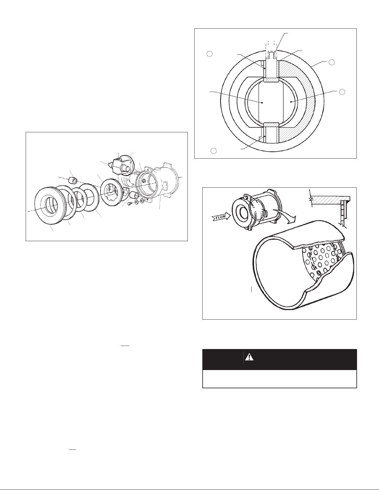
1. Install LN2/4 “lo-noise” insert (25) or “abrasion
sleeve” insert (26) into the body (1) cavity before
inserting the cage/plug subassembly (2)(4)(5)
(6). Ensure that the insert (25)(26) is properly
located within the groove located in the back-
end of the body (1)
NOTE: For proper orientation of LN2, LN3 or LN4
trims, see Figure 6.
WARNING
Do not insert hands/fingers into body (1) or actuator
arm housing (4) openings while actuator is pressurized.