manuals.online logo
Brands
  1. Home
  2. •
  3. Brands
  4. •
  5. CALEFFI
  6. •
  7. Control Unit
  8. •
  9. CALEFFI AutoFill 5350 Series User guide

CALEFFI AutoFill 5350 Series User guide

Technical Characteristics
. Materials: -Body: brass
-Cover: Glass fiber reinforced nylon PA66G30
-Control spindle: stainless steel
-Moving parts: brass
-Diaphragm & seals: NBR
-Filter: stainless steel
. Max working pressure:
. Downstream pressure setting range:
365 psi (25 bar)
6–90 psi (0.5–6 bar)
. Factory setting: 15 psi (1.035 bar)
. Max. working temperature:
. Pressure gauge scale:
. Filter mesh size:
140°F (60°C)
0–100 psi (0–7bar)
0.51 mm (35 mesh)
- Environmental: indoor only
.Suitable fluids: water
. Connections: 3/4” & 1"
3/4” & 1"
3/4" & 1"
3/4" & 1"
size 3/4": 4-7/16"
size 1": 4-3/4"
1/8” NPT
Function
The 5350 series AutoFill™ automatic filling valve is a pressure reducing valve which when installed
on the water inlet piping in closed hydronic systems will maintain system pressure at a set value,
automatically filling up with water as required. Fast fills the system to set pressure then automatically
shuts off the water feed. This product is factory pre-set to 15 psi system pressure. To adjust the
set pressure, simply turn the adjustment knob while observing the integral dowmstream pressure
gauge. This product has the characteristic of being pre-adjustable, which means that it can
be adjusted at the right pressure value before the system charging phase. After installation,
the system pressure will automatically adjust itself to the set value and the water feed will stop when
the set pressure is reached. The internal cartridge containing all the controlling components is pre-
assembled as a self-contained unit, to facilitate inspection and maintenance procedures.
Installation, commissioning and servicing instructions
www.caleffi.com
CALEFFI
NA38445.03
AutoFill
™
Automatic filling valve
5350 Series
© Copyright 2018 Caleffi
Product range
5350 Series AutoFill Automatic filling valve with pressure gauge and pressure setting
adjustment knob with NPT male, Press, and Sweat connections, size 3/4” and 1".
These items are designed for use in closed hydronic systems. Do not use in plumbing applications.
These items do not meet the low-lead plumbing standards of U.S. and Canada.
-NPT male union:
-Sweat union:
-PEX crimp union:
-Press:
-Lay length (press connection):
-Pressure gauge:
SAFETY INSTRUCTION
This safety alert symbol will be used in this manual to draw attention to safety related instructions. When used, the
safety alert symbol means ATTENTION! BECOME ALERT! YOUR SAFETY IS INVOLVED! FAILURE TO
FOLLOW THESE INSTRUCTIONS MAY RESULT IN A SAFETY HAZARD.
CAUTION: All work must be preformed by qualified personnel trained in the proper application,
installation, and maintenance of systems in accordance with all applicable codes and
ordinances.
CAUTION: If the automatic filling unit is not installed, commissioned and maintained properly,
according to the instructions contained in this manual, it may not operate correctly
and may endanger the user.
CAUTION: Make sure that all the connecting pipework is water tight.
CAUTION: When making the water connections, make sure that the unit connecting pipework is
not mechanically overstressed. Over time this could cause breakages, with
consequent water losses which, in turn, could cause harm to property and/or people.
CAUTION: Water temperatures higher than 100°F (38°C) can be dangerous. During the
installation, commissioning and maintenance of the automatic filling valve, take the
necessary precautions to ensure that such temperatures do not endanger people.
Leave this manual for the user.
CAUTION: In the case of highly aggressive water, arrangements must be made to treat the water
before it enters the unit, in accordance with current legislation. Otherwise the unit may
be damaged and will not operate correctly.
Pre-adjustment
AutoFill automatic filling valves in the 5350 series come standard with
an operating adjustment knob and an integral downstream outlet
pressure gauge. This adjustment knob features rotational operation.
The pressure can be adjusted
continuously, resulting in 7 psi
per revolution, with the value
displayed on the outlet gauge.
2
1
|
|
|
|
|
|
|
|
|
|
|
|
|
|
|
|
|
|
|
|
|
|
|
|
|
|
|
|
|
|
|
|
|
|
|
|
|
|
|
|
|
|
|
|
|
|
|
|
|
|
|
|
|
|
|
|
|
|
|
|
|
|
|
|
|
|
|
|
|
|
|
|
|
|
|
|
|
|
|
|
|
|
|
|
|
|
|
|
|
|
|
|
|
|
|
|
|
|
|
|
|
|
|
|
|
|
|
|
|
|
|
|
|
|
|
|
|
|
|
|
|
|
|
|
|
|
|
|
|
|
|
|
|
|
|
|
|
|
|
|
|
|
|
|
|
|
|
|
|
|
|
|
|
|
|
|
|
|
|
|
|
|
|
|
|
|
|
|
|
|
|
|
|
|
|
|
|
|
|
|
|
|
|
|
|
|
|
|
|
|
|
|
|
|
|
|
|
|
|
|
|
|
|
|
|
|
|
|
|
|
|
|
|
|
|
|
|
|
|
|
|
|
|
|
|
|
|
|
|
|
|
|
|
|
|
|
|
|
0
60
20
40
80
100
0
1
25
6
7
3 4
psi
bar
0
60
20
40
80
100
0
1
25
6
7
3 4
psi
bar
WARNING: This product can expose you to chemicals including lead, which is known to the State
of California to cause cancer and birth defects or other reproductive harm. For more
information go to www.P65Warnings.ca.gov.
VENT
Removable self-contained cartridge
The cartridge, containing the diaphragm, strainer, seat, valve port and compensating piston, is pre-assembled as a “self-contained unit” with a cover
and can be easily removed for inspection and maintenance procedures.
1. Filling valve can be installed in either horizontal or vertical position.
Do not install upside down. Do not install outdoors.
2. Caleffi recommends the AutoFill 5350 series filling valve be installed
with separately-purchased shutoff ball valves, code NA39589,
upstream and downstream.
3. The AutoFill 5350 series filling valve does not have an internal check
valve to prevent reverse flow of water. For this reason, a backflow
preventer installed upstream is recommended. Use a Caleffi code
573503A, or other brand that complies with applicable codes.
4. The system pressure is factory pre-set to 15 psi (1.035 bar).
a. To properly reset to a higher desired system pressure
(greater than 15 psi), start by opening the inlet shutoff valve while
keeping the outlet shutoff valve closed. Adjust the operating knob
clockwise (+) to increase the system pressure to the desired value
as indicated on the outlet gauge, approximately 7 psi per revolution.
b. To reset to a lower system (lower than 15 psi), turn the operating
knob counterclockwise (-) until it stops turning, 0 psi. Then, open the
inlet shutoff valve while keeping the outlet shutoff valve closed. Adjust
the operating knob clockwise (+) to increase the system pressure to
the desired value as indicated on the outlet gauge, approximately 7
psi per revolution.
5. When the desired system pressure is indicated on the gauge, slowly
open the outlet shutoff valve, filling the system.
6. During the filling, in fast-fill mode, the valve will automatically control
the system pressure until it reaches the desired value, without the
need to monitor the filling operation itself. After installation, the internal
mechanism will automatically control system pressure to the desired
value.
VENT
VENT
Installation
When checking, cleaning or replacing the complete regulating cartridge:
1. Isolate the filling valve.
2. The special construction of the filling unit does not require any adjustment
of the system pressure, which can be left at the set value.
3. Remove the upper cover. The upper cover is integral with the internal
regulating cartridge.
4. Check and clean the filter.
5. When the cartridge is screwed back into the body, the pressure setting
will return to the original value.
6. Reopen the shut-off valves. The pressure will return to the original set
value.
Maintenance
3 5
Shut-off valve
Ball valve
Ball stop
Thermometer
Differential pressure
by-pass valve
Flow switch
Zone valve
Pump
FlowCal balancing valve
Flow meter
Temperature probe
Safety thermostat
Regulator
Expansion vessel
3-way valve
Pressure switch
Control pocket
Air separator
P
T
F
TT
T
P
F
T
Application diagram
P
M
AX
10
T
M
AX
65
VENT
C
A
LE
Caleffi North America, Inc.
3883 W. Milwaukee Road
Milwaukee, WI 53208
T: 414.238.2360 F: 414.238.2366
7-23-18

This manual suits for next models

5

Other CALEFFI Control Unit manuals

CALEFFI 5360 Series User manual

CALEFFI

CALEFFI 5360 Series User manual

CALEFFI LEGIOMIX 6000 series Guide

CALEFFI

CALEFFI LEGIOMIX 6000 series Guide
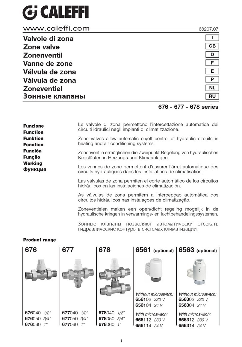
CALEFFI 510 Series User manual

CALEFFI

CALEFFI 510 Series User manual

CALEFFI LEGIOMIX 6000 series Guide

CALEFFI

CALEFFI LEGIOMIX 6000 series Guide

CALEFFI FlowCal 127 Series User manual

CALEFFI

CALEFFI FlowCal 127 Series User manual

CALEFFI 3048 Series User manual

CALEFFI

CALEFFI 3048 Series User manual

CALEFFI 676 Series User manual

CALEFFI

CALEFFI 676 Series User manual

CALEFFI TankMixer 520 Series User manual

CALEFFI

CALEFFI TankMixer 520 Series User manual

CALEFFI 5230 Series User manual

CALEFFI

CALEFFI 5230 Series User manual

CALEFFI 359 Series User manual

CALEFFI

CALEFFI 359 Series User manual

CALEFFI NA51 Series User manual

CALEFFI

CALEFFI NA51 Series User manual

CALEFFI Altecnic SATK40103 Guide

CALEFFI

CALEFFI Altecnic SATK40103 Guide

CALEFFI 200000 User manual

CALEFFI

CALEFFI 200000 User manual

CALEFFI 535H Series User guide

CALEFFI

CALEFFI 535H Series User guide

CALEFFI 519 Series User manual

CALEFFI

CALEFFI 519 Series User manual

CALEFFI 309 Series User manual

CALEFFI

CALEFFI 309 Series User manual

CALEFFI 676 Seies User manual

CALEFFI

CALEFFI 676 Seies User manual

CALEFFI DISCAL 551 Series User manual

CALEFFI

CALEFFI DISCAL 551 Series User manual

CALEFFI 252169A Guide

CALEFFI

CALEFFI 252169A Guide

CALEFFI MixCal 521400A Guide

CALEFFI

CALEFFI MixCal 521400A Guide

CALEFFI 580011 User manual

CALEFFI

CALEFFI 580011 User manual

CALEFFI 636 series User manual

CALEFFI

CALEFFI 636 series User manual

CALEFFI 677 Series User manual

CALEFFI

CALEFFI 677 Series User manual
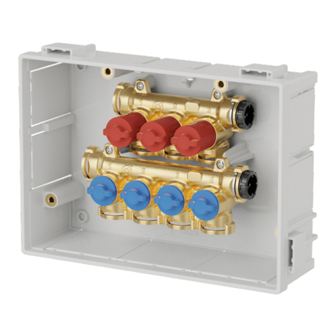
CALEFFI 524 Series User manual

CALEFFI

CALEFFI 524 Series User manual

Popular Control Unit manuals by other brands

Baxi QAA73.110 Basic documentation

Baxi

Baxi QAA73.110 Basic documentation

Chacon 54750 quick guide

Chacon

Chacon 54750 quick guide

Nibe ACS 45 Installer manual

Nibe

Nibe ACS 45 Installer manual

CAME PXC2-32 Installer manual

CAME

CAME PXC2-32 Installer manual

Eaton COOPER POWER SERIES manual

Eaton

Eaton COOPER POWER SERIES manual

XEMEX SUNGATE WatchTalk installation manual

XEMEX

XEMEX SUNGATE WatchTalk installation manual

Swagelok RHPS Series user manual

Swagelok

Swagelok RHPS Series user manual

Armstrong GP-2000 manual

Armstrong

Armstrong GP-2000 manual

Allen-Bradley XM-124 user manual

Allen-Bradley

Allen-Bradley XM-124 user manual

Loctite 97135 Operation manual

Loctite

Loctite 97135 Operation manual

Richter GUT/F Series Installation and operating manual

Richter

Richter GUT/F Series Installation and operating manual

Watts IS-TWH-UTS installation instructions

Watts

Watts IS-TWH-UTS installation instructions

Flow-Rite ProTimer Installation and operation instructions

Flow-Rite

Flow-Rite ProTimer Installation and operation instructions

Allmatic HELIOS KAIROS manual

Allmatic

Allmatic HELIOS KAIROS manual

Festo CAMC-G-S3 manual

Festo

Festo CAMC-G-S3 manual

DeZurik APCO CVS-6000 Installation, operation and maintenance manual

DeZurik

DeZurik APCO CVS-6000 Installation, operation and maintenance manual

Danfoss 088U0200 instructions

Danfoss

Danfoss 088U0200 instructions

iNels RFATV-2 manual

iNels

iNels RFATV-2 manual

manuals.online logo
manuals.online logoBrands
  • About & Mission
  • Contact us
  • Privacy Policy
  • Terms and Conditions

Copyright 2025 Manuals.Online. All Rights Reserved.