cashco CA1 Instruction manual

MODELS CA-1 AND CA-2
BACK PRESSURE / RELIEF REGULATORS
SECTION I
DESCRIPTION AND SCOPE
I.
SECTION II
Recommended Piping Schematic For Back Pressure/Relief Station
Models CA-1 and CA-2 are back pressure/relief regulators used to control upstream (inlet or P1) pressure. Sizes for
CA-1 – 1/8" and 1/4" (DN6 and DN8); for CA-2 – 3/8" and 1/2" (DN10 and DN15). Both models are bronze bodied
units. With proper trim utilization, both units are suitable for liquid and gaseous service. Refer to Technical Bulletin
CA-TB for specific design conditions and selection recommendations.
II. INSTALLATION
INSTALLATION, OPERATION & MAINTENANCE MANUAL IOM-CA
02-20
This is not a safety device and must not be substituted for a code approved pressure
safety relief valve or rupture disc.
1. An inlet block valve should always be installed.
2. If service application is continuous such that
shutdown is not readily accomplished, it is rec-
ommended that an inlet block valve, outlet block
valve, and a manual bypass valve be installed.
3. Pipe unions should be installed to allow removal
from piping.
4. An inlet pressure gauge should be located
approximately ten pipe diameters upstream, and
within sight. An outlet pressure gauge is optional.
5. All installations should include an upstream
safety relief device if the inlet pressure could
exceed the pressure rating of any equipment or
the maximum inlet pressure rating of the unit.
WARNING
The maximum inlet pressure is equal to 1.5 times the
larger number of the stated range spring on the nameplate,
and is the recommended "upper operative limit" for the
sensing diaphragm. Higher pressures could damage the
diaphragm. (Field hydrostatic tests frequently destroy
diaphragms. DO NOT HYDROSTATIC TEST THROUGH
AN INSTALLED UNIT; ISOLATE FROM TEST.)
The instructions in this manual will pertain to both models, unless otherwise stated.
CAUTION
6. Clean piping of all foreign material including chips,
welding scale, oil, grease and dirt before installing
the regulator. Strainers are recommended.
7. In placing thread sealant on pipe ends prior to
engagement, ensure that excess material is
removed and not allowed to enter regulator upon
startup.
8. Flow Direction: Install so the flow direction
aligns with the word “IN” stamped on the body.
Connect the inlet pressure to the body (1) side
connection(s). Fluid will relieve out the bottom
ISO Registered Company

2IOM-CA
connection for Angle or Flow-Thru design and out
the other side connection for Globe design (side
inlet-side outlet).
9. Regulator may be installed in a vertical or
horizontal pipe.
10a. Basic Regulator - (Refer to Figure 1): Regulator
may be rotated around the pipe axis 360°.
Recommended position is with spring chamber
vertical downwards. Orient such that the spring
chamber (2) vent hole does not collect rainwater.
10b. Cryogenic Regulator, Opt-5 – Recommended
installation is in horizontal line with spring
chamber (2) oriented downwards below the body
(1).
11. Regulatorsarenottobedirectburiedunderground.
12. Forinsulatedpipingsystems,therecommendation
is to not insulate the regulator.
7. Observing the inlet (upstream) pressure gauge,
simultaneously rotate the adjusting screw (3)
clockwise (CW) slowly and begin to close the
bypass valve, if installed, until the inlet pressure
begins to rise. Rotate adjusting screw (3) CW until
the desired setpoint is reached.
8. Continue to slowly open the inlet (upstream block
valve. If the inlet (upstream) pressure exceeds
the desired setpoint pressure, rotate the adjusting
screw (3) CCW until the pressure decreases.
9. When flow is established steady enough that both
the outlet and inlet block valves are fully open,
ensure that the bypass valve is closed, if installed.
10. Develop system flow to a level near its expected
normal rate, and reset the regulator setpoint by
turning the adjusting screw (3) CW to increase
inlet pressure, or CCW to reduce inlet pressure.
11. Reduce system flow to a minimum level and
observe setpoint. Inlet pressure will rise from the
setpoint of Step 9. (Assure that this rise does not
exceed the stated upper limit of the range spring
(6) by greater than 50% i.e. 40-90 psig (2.8 - 6.2
Barg) range spring (6), at maximum flow the inlet
pressure should not exceed 1.5 x 90 psig (6.2
Barg), or 135 psig (9.3 Barg). If it does, consult
factory).
12. Increase flow to maximum level, if possible. Inlet
(upstream or P1) pressure should fall off. Readjust
setpoint as necessary at the normal flow rate.
IV. START-UP
1. Start with the block valves closed. A bypass valve
may be used to maintain inlet pressure in the
upstream system without changing the following
steps.
2. Relax the range spring (6) by turning the adjusting
screw (3) counter clockwise (CCW) a minimum of
three (3) full revolutions. This reduces the inlet
(upstream) pressure setpoint.
3. If it is a “hot” piping system, and equipped with
a bypass valve, slowly open the bypass valve
to pre-heat the system piping and to allow slow
expansion of the piping. Closely monitor inlet
(upstream) pressure via gauge to assure not
over-pressurizing. NOTE: If no bypass valve is
installed, extra caution should be used in starting
up a cold system; i.e. do everything slowly.
4. Crack open the inlet (upstream) block valve.
5. Slowly open the outlet (downstream) block valve
observing the inlet (upstream) pressure gauge.
Determine if the regulator is flowing. If not, slowly
rotate the regulator adjusting screw (3) clockwise
(CW - viewed from spring chamber (2) top) until
flow begins.
6. Continue to slowly open the outlet (downstream)
block valve until fully open.
SECTION IV
III. PRINCIPLE OF OPERATION the diaphragm (11) down, closing the port; as inlet
pressure increases, the diaphragm (11) pushes
up and the port opens.
2. A complete diaphragm (11) failure will cause the
regulator to fail closed.
1. Movement occurs as pressure variations register
on the diaphragm (11). The registering pressure
is the inlet, P1, or upstream pressure. The range
spring (6) opposes diaphragm (11) movement. As
inlet pressure drops, the range spring (6) pushes
SECTION III

IOM-CA 3
SECTION V
V. SHUTDOWN
A. General:
1. Maintenance procedures hereinafter are
based upon removal of the regulator unit from
the pipeline where installed.
2. Owner should refer to owner's procedures for
removal, handling, cleaning and disposal of
nonreusable parts, i.e. gaskets, etc.
3. Refer to Figure 1, Model CA-1 or CA-2 for
the basic regulator. Blow-ups of options are
included with each drawing.
B. Diaphragm Replacement
1. On systems with a bypass valve, and where
system pressure is to be maintained as the
regulator is shut down, slowly open the bypass
valve while closing the inlet (upstream) block
valve. Fully close the inlet (upstream) block
valve. (When on bypass, the system pressure
must be constantly observed and manually
regulated. Close the outlet (downstream) block
valve.
2. If the regulator and system are to both be
shut down, slowly close the inlet (upstream)
block valve. Close the outlet (downstream)
valve only if regulator removal is required.
SECTION VI
VI. MAINTENANCE 2. Relax range spring (6) by loosening the
locknut (4) and turning adjusting screw (3)
CCW until removed from spring chamber (2).
NOTE: If the Option -2 handwheel is utilized,
the adjusting screw (3) and lock nut (4) are re-
placed with a knob (18) and lock nut (4). With
the Option-22 panel mounting w/handwheel,
the adjusting screw (3) and lock nut (4) are
replaced with a knob (18), lock nut (4) and a
panel mounting nut (19).
3. Loosen spring chamber (2) by placing wrench
on “flats” and rotating CCW.
4. Remove spring chamber (2), spring button (5)
range spring (6), and diaphragm stop (9).
5. Remove the diaphragm subassembly
consisting of the pressure plate nut (7), lock
washer (8), pressure plate (10), diaphragm
(11), plug gasket (13) and plug (14). NOTE:
Refer to the quantity of diaphragms (11)
incorporated per the bill of materials listing.
Depending on inlet pressure level, multiple
metal diaphragms (11) may be “stacked”.
1. Securely install the body (1) in a vise with the
spring chamber (2) directed upwards.
6. Loosen pressure plate nut (7) and separate all
parts (7, 8, 10, 11, 13 & 14) of the diaphragm
subassembly.
7. Inspect pressure plate (10) to ensure no
deformation due to over-pressurization. If
deformed, replace.
SPRING UNDER COMPRESSION. Prior to
removing spring chamber, relieve spring
compression by backing out the adjusting screw.
Failure to do so may result in flying parts that
could cause personal injury.
WARNING
CAUTION
To prevent damage to body, use lead jaws when
placing body in a vise. Position so that vise closes
over inlet and outlet of the body.
WARNING
SYSTEM UNDER PRESSURE. Prior to performing
any maintenance, isolate the regulator from the
system and relieve all pressure. Failure to do so
could result in personal injury.
Model's CA-1/CA-2 Diaphragm Subassembly
CAUTION
Do not walk away and leave a bypassed
regulator unattended.
8
11
13
7
10
14

4IOM-CA
8. Remove diaphragm gasket (12) for metal
diaphragm (11). NOTE: No diaphragm
gasket (12) for composition diaphragm (11).
9. Clean body (1) and diaphragm flange. NOTE:
On regulators originally supplied as “oxygen
clean”, Option -5 or Option -55, maintenance
must include a level of cleanliness equal
to Cashco's cleaning standard #S-1134.
Contact factory for details.
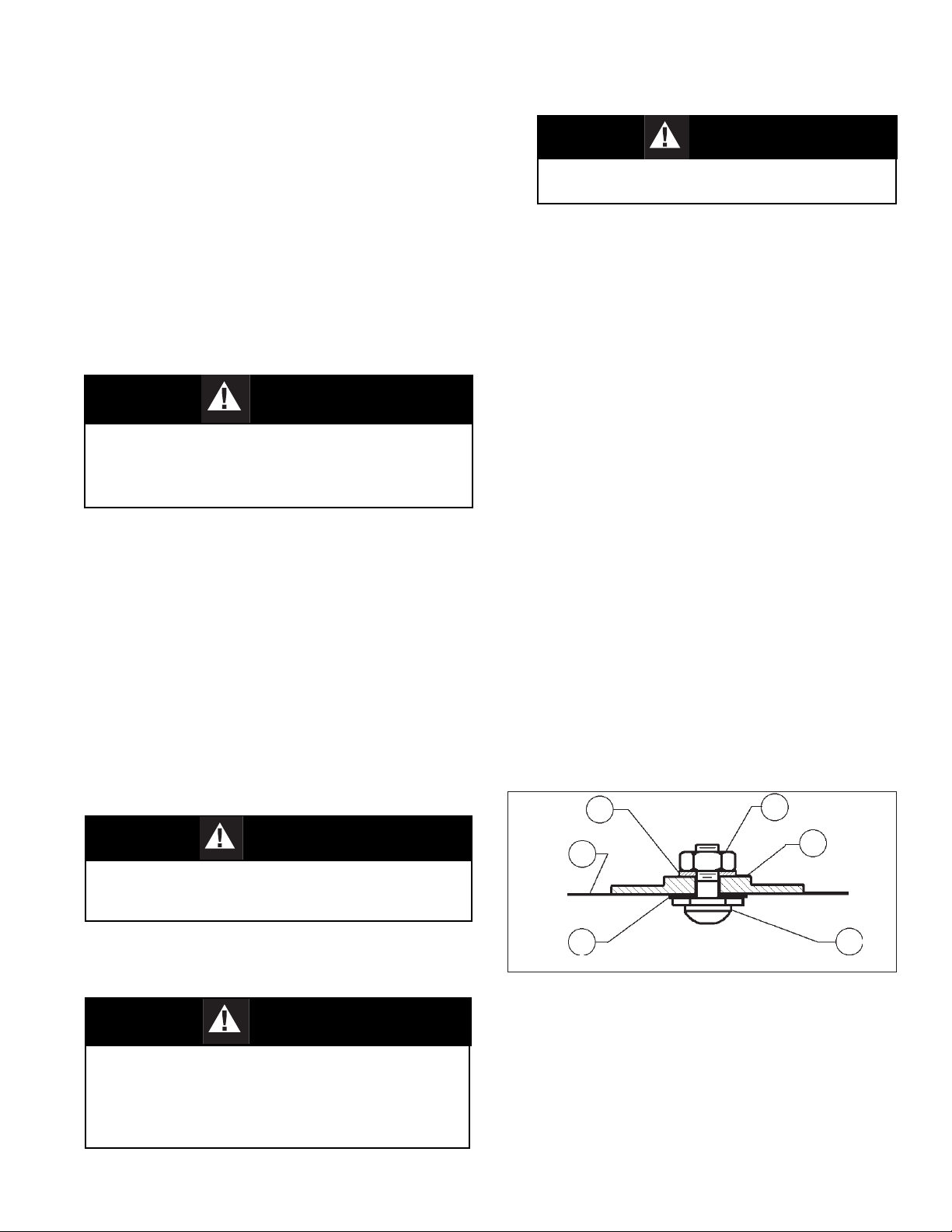
10. Reassemble diaphragm subassembly by
placing plug gasket (13), diaphragm(s) (11),
pressure plate (10) and lock washer (8)
over threaded post of plug (14). Ensure the
pressure plate (10) is placed with curved outer
rim down next to the diaphragm (11) surface.
Place a thread sealant compound similar to
Loctite #271 on the threads of the plug's (14)
post prior to tightening the pressure plate nut
(7) to the following torque values:
15. Reinstall adjusting screw (3) with locknut (4)
into the spring chamber (2).
16. Pressurize with air and spray liquid leak
detector to inspect entire body (1) and spring
chamber (2) for leakage. Ensure that an inlet
pressure is maintained during this leak test
of at least mid-range spring level; i.e. 40-90
psig (2.8-6.2 Barg) range spring, 65 psig (4.5
Barg) test pressure minimum.
C. Trim Replacement
1. Trim inspection requires the diaphragm
subassembly be removed. Refer to previous
procedure, Section VI.B.
2. Inspect inside surface of seat ring (15) and
seating surface of plug (14). If seating surface
shows signs of erosion/wear, the seat ring
(15) and plug (14) should be replaced.
3. Clean body (1) cavity. Clean all parts to be
reused. NOTE: On regulators originally
supplied as “oxygen clean”, Option -5 or
Option -55, maintenance must include a level
of cleanliness equal to Cashco's cleaning
standard #S-1134. Contact factory for details.
4. Inspect the surface in the body (1) cavity
where seat ring (15) rests. If surface area of
either mating part shows signs of erosion/
wear, replace with new regulator.
5. Place seat ring (15) in center of body (1)
cavity. Ensure that the shoulder on outer
edge of seat ring (15) faces up towards the
diaphragm (11).
6. Reinstall diaphragm subassembly per
Section VI.B., Diaphragm Replacement.
7. Bench test unit for suitable operation. NOTE:
Regulators are not tight shut off devices.
Even if pressure falls below setpoint, a
regulator may or may not develop bubble
tight shut off. In general, tighter shut off can
be expected with composition seat.
8. Pressurize with air and spray liquid leak
detector to inspect entire body (1) and spring
chamber (2) for leakage. Test pressure
should be the maximum allowed by the range
spring at the inlet.
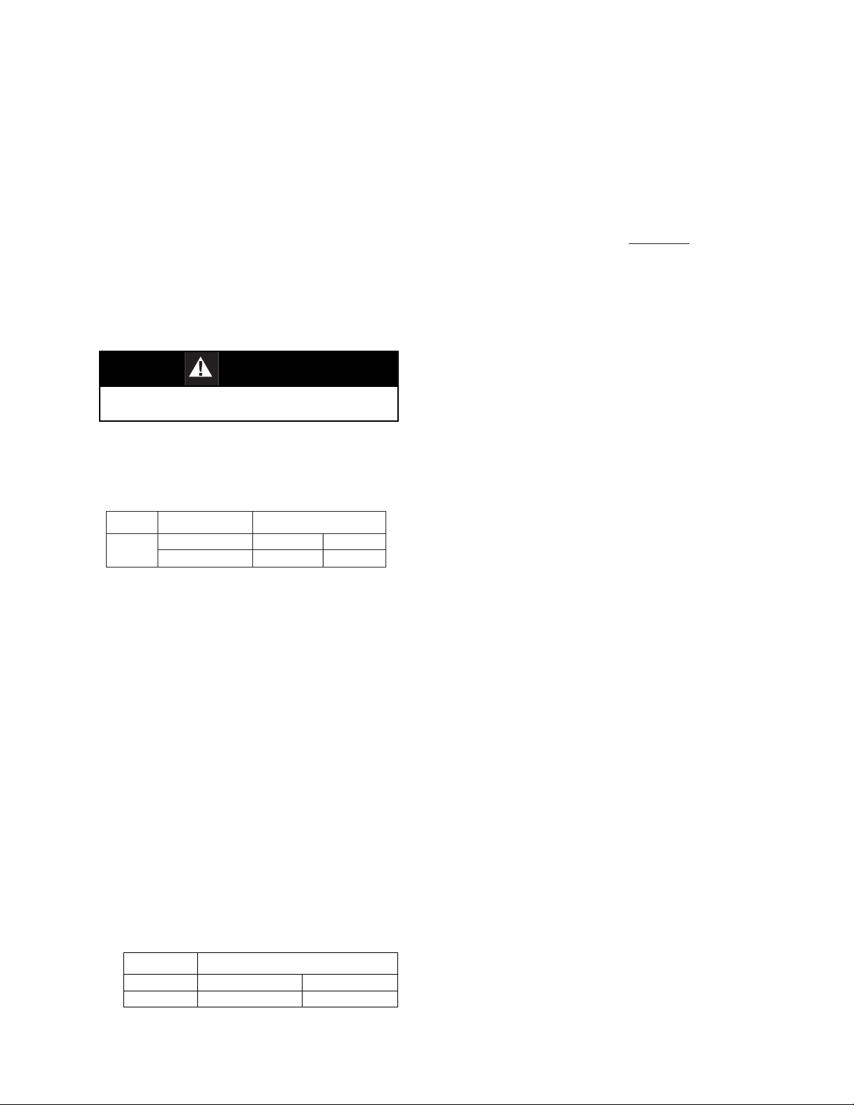
Model Torque
CA-1 20-25 Ft-lbs. 27-34 N-m
CA-2 25-30 Ft-lbs. 34-40 N-m
Sizes Diaphragm Torque
ALL Metal 60 In-lbs. 6.8 N-m
Composition 15 In-lbs. 1.7 N-m
11. Place diaphragm gasket (12) on
body (1), then insert the diaphragm
subassembly into the body (1).
12. Place diaphragm stop (9) and range
spring (6) over the pressure plate nut
(7) of the diaphragm subassembly.
13. Place multi-purpose, high temperature
grease into depression of spring button
(5) where adjusting screw (3) bears. Set
spring button (5) onto range spring (6);
ensure spring button (5) is laying flat.
14. Rotate the spring chamber (2) CW by
hand into the threaded portion of the
body (1) assuring not to cross thread.
Continue hand rotating CW until firmly
seated against the diaphragm stop (9).
Wrench tighten securely to the following
torque values:
Use only gaskets supplied by Cashco, Inc.
for these products.
CAUTION

IOM-CA 5
2. Regulator inlet (upstream) too high:
3. Leakage through the spring chamber vent hole.
4. Sluggish operation.
1. Erratic operation; chattering.
SECTION VII
VII. TROUBLE SHOOTING GUIDE
Possible Causes Remedies
A. Oversized regulator. A1.Check actual flow conditions, re-size regulator for minimum and
maximum flow.
A2.Increase flow rate.
A3.Decrease regulator pressure drop; decrease inlet pressure by
placing a throttling orifice in inlet piping union.
A4.Install next step higher range spring. Contact factory.
A5.Before replacing regulator, contact factory.
B. Worn plug. B. Replace regulator.
Possible Causes Remedies
A. Regulator undersized. A1.Confirm by opening bypass valve together with regulator.
A2.Check actual flow conditions, re-size regulator; if regulator has
inadequate capacity, replace with larger unit.
B. Incorrect range spring (screwing in CW
of adjusting screw does not allow bringing
pressure level up to proper level.)
B. Replace range spring with proper lower range. Contact factory
C. Too much rise (build). C1.Review rise (build) expected.
C2.Contact factory.
Possible Causes Remedies
A. Normal-life diaphragm failure. A. Replace diaphragm.
B. Abnormal short-life diaphragm failure. B1.Can be caused by excessive chattering. See No.1. to
remedy chatter.
B2.Can be caused by corrosive action. Consider alternate
diaphragm material.
B3.For composition diaphragms, assure not subjecting to over-
temperature conditions.
B4.Upstream (inlet) pressure build-up occurring that overstresses
diaphragms. Relocate regulator or protect with safety relief valve.
Possible Causes Remedies
A. Plugged spring chamber vent. A. Clean vent opening.
B. Fluid too viscous. B. Heat fluid. Contact factory.

6IOM-CA
SECTION VIII
NEW REPLACEMENT UNIT:
Contact your local Cashco, Inc., Sales Represen-
tative with the Serial Number and Product code.
With this information they can provide a quotation
for a new unit including a complete description,
price and availability.
–7–
VIII. ORDERING INFORMATION
NEW REPLACEMENT UNIT vs PARTS "KIT" FOR FIELD REPAIR
To obtain a quotation or place an order, please retrieve the Serial Number and Product Code that was stamped
on the metal name plate and attached to the unit. This information can also be found on the Bill of Material
("BOM"),a parts list that was provided when unit was originally shipped. (Serial Number typically 6 digits).
Product Code typical format as follows: (last digit is alpha character that reflects revision level for the product).
PARTS "KIT" for FIELD REPAIR:
Contact your local Cashco, Inc., Sales Represen-
tative with the Serial Number and Product code.
Identify the parts and the quantity required to repair
the unit from the "BOM" sheet that was provided
when unit was originally shipped.
NOTE: Those part numbers that have a quantity indicated
under "Spare Parts" in column "A” reflect minimum
parts required for inspection and rebuild, - "Soft
Goods Kit". Those in column “B” include minimum
trim replacement parts needed plus those "Soft
Goods" parts from column "A".
If the "BOM" is not available, refer to the cross-
sectional drawings included in this manual for part
identification and selection.
A Local Sales Representative will provide quotation
for appropriate Kit Number, Price and Availability.
CAUTION
Do not attempt to alter the original construction
of any unit without assistance and approval from
the factory. All purposed changes will require a
new name plate with appropriate ratings and new
product code to accommodate the recommended
part(s) changes.
The contents of this publication are presented for informational purposes only, and while every effort has been made to ensure their accuracy, they are not to be
construed as warranties or guarantees, express or implied, regarding the products or services described herein or their use or applicability. We reserve the right to
modify or improve the designs or specifications of such product at any time without notice.
Cashco, Inc. does not assume responsibility for the selection, use or maintenance of any product. Responsibility for proper selection, use and maintenance of any
Cashco, Inc. product remains solely with the purchaser.

IOM-CA 7
MODEL CA-1
Figure 1:
Basic Model CA-1 with
3-Connection Flow-Thru Body
Option-2 Handwheel
Option-5 Cryogenic Construction
Installed in horizontal line with spring chamber ori-
ented downwards below the body. Body and spring
chamber Item Numbers are identical to Figure 1.
IRepair Parts
Item No. Description Kit B
1 Body
2 Spring Chamber
3 Adjusting Screw
4 Lock Nut
5 Spring Button
6 Range Spring
7 Pressure Plate Nut
8 Lock Washer
9 Diaphragm Stop
10 Pressure Plate
11 Diaphragm
12 Diaphragm Gasket
13 Plug Gasket
14 Plug
15 Seat Ring
17 Nameplate
18 Knob
*
*
*
*
*
*
*
*
*
*
*
*
3
4
2
5
6
7
8
9
10
11
12
13
14
15
1
18
4
2

MODEL CA-2
Figure 1:
Basic Model CA-2 with
3-Connection Flow-Thru Body
Option-22 Panel Mounting (handwheel portion is same
for Option-2 Handwheel)
ITEMS NOT SHOWN
16 Closing Cap
20 Closing Cap Gasket
21 Drive Screw
Option-5 Cryogenic Construction
Installed in horizontal line with spring chamber ori-
ented downwards below the body. Body and spring
chamber Item Numbers are identical to Figure 1.
Item No. Description
1 Body
2 Spring Chamber
3 Adjusting Screw
4 Lock Nut
5 Spring Button
6 Range Spring
7 Pressure Plate Nut
8 Lock Washer
9 Diaphragm Stop
10 Pressure Plate
11 Diaphragm
12 Diaphragm Gasket
13 Plug Gasket
14 Plug
15 Seat Ring
17 Nameplate
18 Handhweel or Knob
19 Mounting Nut
Repair Parts
Kit B
*
*
*
*
*
*
*
*
*
*
*
*
*
3
4
2
5
6
7
8
9
10
11
12
13
14
15
1
18
4
19
3
2
Cashco, Inc.
P.O. Box 6
Ellsworth, KS 67439-0006
PH (785) 472-4461
Fax. # (785) 472-3539
www.cashco.com
email: [email protected]
Printed in U.S.A. IOM-CA
Cashco do Brasil, Ltda.
Al.Venus, 340
Indaiatuba - Sao Paulo, Brazil
PH +55 11 99677 7177
Fax. No.
www.cashco.com
email: [email protected]
Cashco GmbH
Handwerkerstrasse 15
15366 Hoppegarten, Germany
PH +49 3342 30968 0
Fax. No. +49 3342 30968 29
www.cashco.com
email: [email protected]

Cashco, Inc. declares that the products listed in the table below has been found to comply with the Essential
Health and Safety Requirements relating to the design and construction of products intended for use in potentially
explosive atmospheres given in Annex II of the ATEX Directive 2014/34/EU. Compliance with the Essential
Health and Safety Requirements has been assured by compliance with EN ISO 80079-36:2016 and EN ISO
80079-37:2016. The product will be marked as follows:
II 2 G
Ex h IIB T6... T1 Gb
1000ATEXR1 X
The ‘X’ placed after the technical file number indicates that the product is subject to specific conditions of use as
follows:
1. The maximum surface temperature depends entirely on the operating conditions and not the equipment
itself. The combination of the maximum ambient and the maximum process medium temperature shall
be used to determine the maximum surface temperature and corresponding temperature classification,
considering the safety margins described prescribed in EN ISO 80079-36:2016, Clause 8.2. Additionally, the
system designer and users must take precautions to prevent rapid system pressurization which may raise
the surface temperature of system components and tubing due to adiabatic compression of the system gas.
Furthermore, the Joule-Thomson effect may cause process gases to rise in temperature as they expand
going through a regulator. This could raise the external surface temperature of the regulator body and
the downstream piping creating a potential source of ignition. Whether the Joule-Thomson effect leads to
heating or cooling of the process gas depends on the process gas and the inlet and outlet pressures. The
system designer is responsible for determining whether the process gas temperature may raise under any
operating conditions.
2. Where the process medium is a liquid or semi-solid material with a surface resistance in excess of 1GΩ,
special precautions shall be taken to ensure the process does not generate electrostatic discharge.
3. Special consideration shall be made regarding the filtration of the process medium if there is a potential for
the process medium to contain solid particles. Where particles are present, the process flow shall be <1m/s
(<3.3 ft/s) in order to prevent friction between the process medium and internal surfaces.
4. Effective earthing (grounding) of the product shall be ensured during installation.
5. The valve body/housing shall be regularly cleaned to prevent build up of dust deposits.
6. Regulators must be ordered with the non-relieving option (instead of the self-relieving option) if the process
gas they are to be used with is hazardous (flammable, toxic, etc.). The self-relieving option vents process
gas through the regulator cap directly into the atmosphere while the non-relieving option does not. Using
regulators with the self-relieving option in a flammable gas system could create an explosive atmosphere in
the vicinity of the regulator.
7. Tied diaphragm regulators with outlet ranges greater than 7 barg (100 psig) should be preset to minimize the
risk that improper operation might lead to an outboard leak and a potentially explosive atmosphere.
8. All equipment must only be fitted with manufacturer’s original spare parts.
9. Ensure that only non-sparking tools are used, as per EN 1127-1, Annex A.
ATEX 2014/34/EU: Explosive Atmospheres and Cashco Inc. Products

10 IOM-CA
REGULATORS
PRODUCT
31-B, 31-N
1164, 1164(OPT-45)
1171, 1171(OPT-45), 1171(CRYO)
2171, 2171(OPT-45), 2171(CRYO), 3171
1465, 3381, 3381(OPT-45), 3381(OPT-40)
4381, 4381(OPT-37), 4381(CRYO), 4381(OPT-45), 5381
MPRV-H, MPRV-L
PBE, PBE-L, PBE-H
CA-1, CA-2
CA1, SA1, CA4, SA4, CA5, SA5
DA2, DA4, DA5, DA6, DA8
DA0, DA1, DAP, SAP
SLR-1, SLR-2, PTR-1
ALR-1, ULR-1, PGR-1
BQ, BQ(OPT-45), BQ(CRYO)
123, 123(CRYO), 123(OPT-45), 123(OPT-46G)
123-1+6, 123-1+6(OPT-45), 123-1+6(OPT-46G), 123-1+6+S, 123-1+6+S(OPT-40)
1000HP, 1000HP(OPT-37), 1000HP(OPT-45), 1000HP(OPT-45G), 1000HP(CRYO)
1000HP-1+6, 1000HP-1+8, 1000LP, 1000LP(OPT-45), 1000LP(OPT-46G)
6987
8310HP, 8310HP-1+6, 8310HP-1+8, 8310LP, 8311HP, 8311LP
345, 345(OPT-45)
BA1/BL1, PA1/PL1
C-BPV, C-PRV, C-CS
D, D(CRYO), D(OPT-37), D(OPT-20), D(OPT-45)
DL, DL(LCC), DL(OPT-45)
BR, BR(CRYO)
HP, HP(LCC), HP(OPT-45), HP(OPT46G), HP-1+6+S(OPT-40), HP-1+6+S
P1, P2, P3, P4, P5, P7
B2, B7
POSR-1, POSR-2
5200P, 5300P
135
NW-PL, NW-SO
CG-PILOT
FG1
CONTROL
VALVES
RANGER, 987, PREMIER
964, 521, 988, 988-MB, 989
2296/2296HF
SCV-30, SCV-S
FL800/FL200
TANK
BLANKETING
8700, 8910, 8920, 8930, 8940
2100, 2199
3100, 3200, 3300, 3400, 3500, 3600, 3700
1078, 1088, 1100, 1049
5100, 5200, 5400 ,5500
4100, 4200, 4300, 4400, 4500, 4600
MISC 764P/PD, 764-37, 764T
Other manuals for CA1
1
This manual suits for next models
1
Table of contents
Other cashco Industrial Equipment manuals
Popular Industrial Equipment manuals by other brands

ABB
ABB HT608197 Operation manual

Festo
Festo DGP-B Series operating instructions

ABB
ABB Power2 340-H Operation manual

Seifert
Seifert 750640B001 user manual

Wheaton
Wheaton W348923-C instruction manual

RADEMACHER
RADEMACHER RolloTron Comfort 1623 45 19 Translation of the Original Operating and Assembly Manual