Casio EG-5 User manual

ELECTRIC GUITAR
EG-5
(without price)

— 2 —
CONTENTS
SPECIFICATIONS
GENERAL
Body: Inner; Die cast aluminum
Outer; High impact PS resin
Neck: Hard maple
Pickup: CASIO original
Guitar controls: Main Volume, Guitar Mix, Guitar Volume, Distortion ON/OFF, Distortion Drive
Tape recorder: Recording system: Stereo
Playback system: Stereo (monaural speaker and monaural guitar output)
Tracks: 4-track, 2-channel stereo
Tape type: Normal
Tape speed: 4.76 cm/sec.
Fast forward/reverse time: approximately 150 sec. (C-60)
Recording level: Auto (automatically adjusted to prevent distortion)
Basic functions: REC, PLAY, F.FWD, STOP/EJECT, PAUSE
Other functions: Tape pitch adjustment (+/-3%), Auto stop
Built-In speaker: 10 cm dia. 2.0 W input rating: 1 pce.
Terminals: Line In Jack [stereo mini jack, input impedance: 15 ohms]
Guitar Out Jack [monaural standard jack, output impedance: 4.5 ohms,
output voltage: 0.25 V (RMS) Maximum]
Phones Jack [Stereo mini jack, output impedance: 4.5 ohms,
output voltage: 0.50 V (RMS) Maximum]
AC Adaptor Jack (DC 9 V)
Power source: DC: 6 AA size dry batteries
Battery life: Approx. two hours (R14P/SUM-2)
Approx. four hours (LR14/AM2)
AC: AC Adaptor AD-5
Power comsumption: 7.7 W
Dimensions (HWD): 75 x 966 x 324 mm
(2-15/16 x 38-1/16 x 12-3/4 inches)
Weight: 3.2 kg (7.0 lbs) including batteries
ELECTRICAL
Current drain with 9 V DC:
No Sound Output 92 mA ±20%
Maximum volume 750 mA ±20%
Speaker Output Level (Vrms with 8 ohms load)
with 6th string picked at 12th fret from 5th string 780 mA ±30%
Phone Output Level (Vrms with 8 ohms load)
with 6th string picked at 12th fret from 5th string 65 mA ±30%
Guitar Output Level (Vrms with 8 ohms load)
with 6th string picked at 12th fret from 5th string 32 mA ±30%
Minimum Operating Voltage: 6.3 V
Specifications.................................................................................... 2
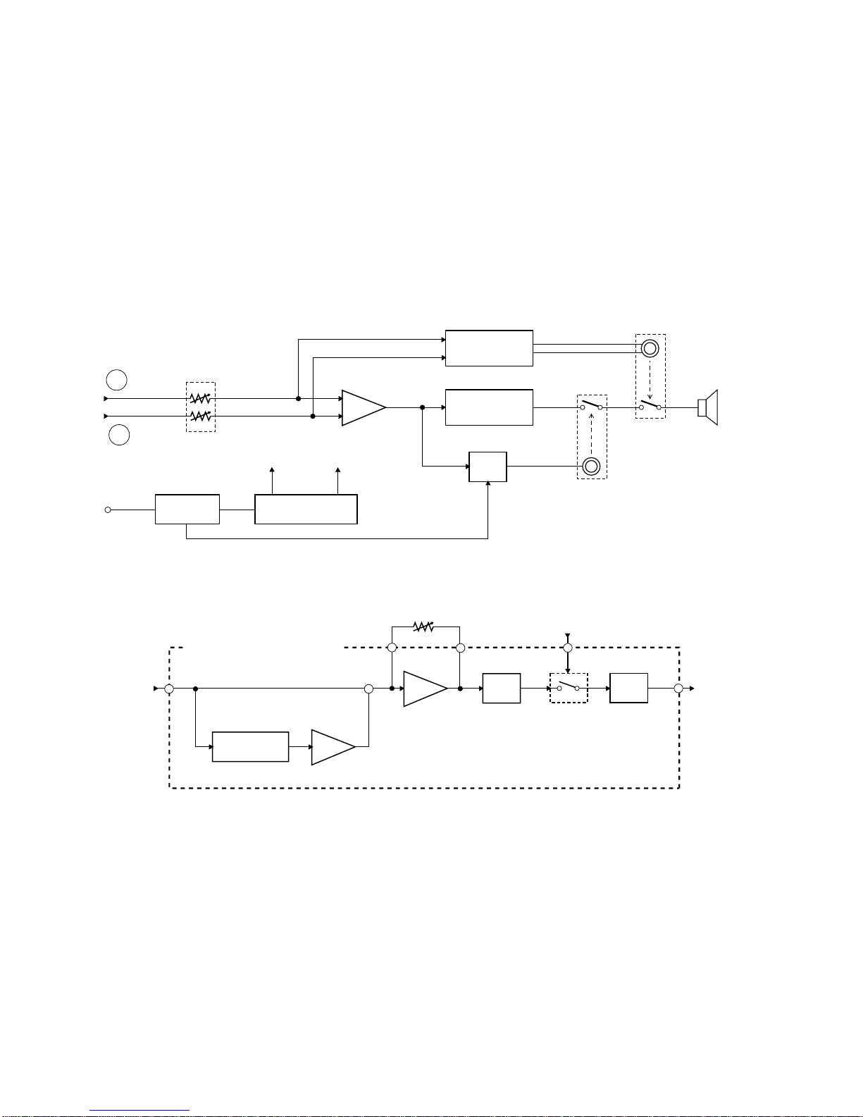
Block Diagrams................................................................................. 3
Disassembly Instructions ................................................................ 5
Tuning ................................................................................................ 6
Adjustment ........................................................................................ 7
Circuit Description ............................................................................ 8
Wiring Diagram.................................................................................. 9
Schematic Diagrams....................................................................... 10
Exploded View................................................................................. 14
Parts List.......................................................................................... 15

— 3 —
BLOCK DIAGRAMS
Pickup Hum
Cancel VR11
Guitar Volume Distortion
Changeover
T54, T55 Distortion
Circuit
Mixer
IC53
Guitar MIX
VR52
Distortion
Button Flip-Flop
T51, T52
Head Head Amp.
TA8142AP
IC41
Mute
T45, T46 Mute
T43, T44
Mixer R
IC42
Mixer L
IC42
Line IN
Line IN Amp.
HOT1
HOT2
Filter
Distortion Volume
VR51
Bias Circuit
Leaf Switch
Motor
Cassette Mechanism
REC
Switch
S41
VR31 VR32 Tape Speed Volume
SVC MVC (Motor Drive Signal) T42
T41, L41
BIAS
L-CH
R-CH
+
A
B
GUITAR-R
TAPE-R
AUX-R
GUITAR-L
TAPE-L
AUX-L
RAUX
LAUX
T21, T22
VR13
A
B
IC53

— 4 —
A
B
Main Volume
VR53 RVOUT
LVOUT
Mixer
Headphone Amp.
LA4525 IC21
Power Amp.
LA4127 IC13
Mute
T23
Phone Output
Guitar Output
Speaker
Power Supply Circuit
D22, T24
Power Switch
S21
VC 9 V VCC 9 V
DC IN 9V
Amp.
Amp. Clipper
Band-Pass Filter
IC51
VR51
Distortion Volume
DI505~DI508
IC51
IC52 T56
Filter
IC52
< DISTORTION CIRCUIT >
+
IC12

— 5 —
DISASSEMBLY INSTRUCTIONS
Note: EG-5 has a detachable neck. So do not loosen the four black screws attaching the neck to the body at
usual repairs. Only when replacing the neck, remove the screws.
Black Screws
< Figure 1 >
To open the lower body
1. Remove the battery cover.
2. Remove the eighteen screws holding the lower body.
3. Open the lower body.
To disassemble the cassette mechanism
1. Open the lower body.
2. Desolder PC cable, JD cable and PH cable on JCM370-MA4M PCB.
3. Remove three screws on JCM370-MA2M PCB and four screws on JCM370-MA4M PCB.
4. Remove all buttons from the cassette mechanism.
5. Remove the four screws holding the cassette mechanism.
6. Remove the cassette mechanism from the upper body.
To disassemble the pickup
1. Remove all strings from the guitar.
2. Open the lower body.
3. Desolder the cable of the pickup on JCM370-MA1M PCB.
4. Remove two black screws on the upper body.
To disassemble the bridge
1. Remove all strings from the guitar.
2. Remove four screws on the bridge.
To disassemble the neck
1. Remove all strings from the guitar.
2. Remove the four black screws on the lower body.

— 6 —
TUNING
Most guitar players tune their guitar by themselves as they like.
Do not adjust tunings of a customer’s guitar at usual repairs, because the tunings may be re-adjusted by a
customer. Only after replacing the neck, the bridge or the pickup, adjust a certain tuning item shown in the
following table.
Tools/Equipments required
4 mm hexagon key (Accessory tool)
1.5 mm hexagon key (Accessory tool)
Guitar tuning meter
TUNING PROCEDURE
Please refer to the tuning instructions in the operation namual also.
To adjust warp of neck
1. Check the space between a string and the 10th fret when pressing the string at the 1st fret and at the 19th
fret.
And check all strings.
2. If the space exceeds 0.3 mm, straighten the neck by turning the nut in the head clockwise with a 4 mm
hexagon key.
To adjust pickup height
1. Press a string at 22nd fret.
2. Use a screw driver, adjust a height of the pickup to be 2 mm off from the string by turning two screws at both
ends of the pickup.
To adjust string height
1. Use a 1.5 mm hexagon key, adjust a height of the 1st string to be 2 mm above the 14th fret by turning two
hexagon socket screws at the 1st saddle in the bridge.
2. Adjust height of other strings by the same way.
To adjust octave pitch
1. Use a guitar tuning meter, tune the 1st string at open string to the standard pitch.
2. Use a guitar tuning meter, compare pitch of two tones, a tone at the 12th fret with a harmonic*.
3. If pitch of the tone at the 12th fret is sharper over 3 cents than pitch of the harmonic tone, turn the adjustment
screw clockwise.
4. If pitch of the tone at the 12th fret is flatter over 3 cents than pitch of the harmonic tone, turn the adjustment
screw counterclockwise.
5. Repeat steps 1 to 4 until the differnce of pitch between two tones is within 3 cents.
6. Adjust octave pitch of other strings.
* Harmonic: An overtone produced by touching a string above the 12th fret with a finger and by picking the
string just before freeing the string.
Items to be tuned Replaced Part
Warp of neck Neck
Pickup height Pickup
String height Bridge
Octave pitch Bridge

— 7 —
ADJUSTMENT
Equipments required
Oscilloscope
Frequency counter
Test tapes, MTT-111N (0004 5032) and MTT-113N (0004 5033)
Two 8-ohm resistors
Pre-adjustment procedure
1. Clean the head and all tape handling surfaces using standard cleaner and cotton swabs.
2. Connect an 8-ohm dummy load to headphone jack of each channel.
3. Set the main volume to the maximum.
4. Set the tape speed volume to the center position.
Head azimuth adjustment
Never use a magnetized screwdriver for this adjustment.
The head azimuth adjustment screw is located just under the notch which can be seen when opening the
cassette door.
1. Connect a oscilloscope to the dummy loads.
2. Set a tape MTT-113N holding the door open, and playback the tape.
3. By turning the adjustment screw slowly, adjust for amplitude of both channels at maximum and adjust for
the waveforms in the same phase reading on the oscilloscope.
8-ohm Dummy Load
Phone Jack
8-ohm Dummy Load
R-ch
L-ch
EG-5
Oscilloscope
Ch 1
Ch 2
OK
NG
NG
< Figure 2 >
Tape speed adjustment
The tape speed adjustment volume VR32 is located on M370-MA3M PCB.
1. Connect a frequency counter to the dummy load.
2. Playback a test tape MTT-111N.
3. By turning the volume, adjust for 3000 Hz ±30 Hz reading on the frequency counter.
Phone Jack
8-ohm Dummy Load
EG-5 Frequency Counter
< Figure 3 >

— 8 —
CIRCUIT DESCRIPTION
Pickup
The pickup is a humbacking pickup, which consists of the two coils connected in series opposition. Each coil
has the same turns but it has the opposite polarity of the core to the other one.
Hum Cancel Circuit
By adding two outputs from the pickup, the hum cancel circuit removes a hum noise, it also doubles amplitude
of the signal.
Distortion Circuit
The distortion circuit adds a distortion effect to the original signal from the pickup. The circuit cuts off peak of
the waveform, it also produces a sound signal like a howling sound.
Head Amp. (TA8142AP)
The internal block diagram is shown in Figure 5.
S
S
N
N
Noise
Signal
Noise Noise
Signal
Humbacking Pickup
Output2 Output1
< Figure 4 >
12
13
ALC
PIN1
PNF1
PNF2
PIN2
RFN1
RIN1
ALC
RIN2
RNF2
GND
ROt2
ROt1
10
9
Ch2
Ch1
Ch2
Ch1
16
15
14
11
Vref2
Vref1
1
2
POt1
3
Iref
8
7
POt2
6
VCC
54
CG
< Figure 5 >

— 9 —
WIRING DIAGRAM
HOT1
HOT2
SHIELD
PU-B
PU-W
PU-BK
SP+
SP- PS-BL
PS-W
AG
VCC
GVOL
RVOUT
LVOUT
RAUX
LAUX
MVC
JA-8
JA-7
JA-6
JA-5
JA-4
JA-3
JA-2
JA-1
JA-8
JA-7
JA-6
JA-5
JA-4
JA-3
JA-2
JA-1
VC
LAUX
RAUX
LVOUT
RVOUT
AMPOUT
SP+
JB-7
JB-6
JB-5
JB-4
JB-3
JB-2
JB-1
JB-7
JB-6
JB-5
JB-4
JB-3
JB-2
JB-1
MVC
AG
VCC
MIXOUT
PG
JC-5
JC-4
JC-3
JC-2
JC-1
JC-5
JC-4
JC-3
JC-2
JC-1
VC
MVC
A
PG
SVC
B
JF-6
JF-5
JF-4
JF-3
JF-2
JF-1
JF-6
JF-5
JF-4
JF-3
JF-2
JF-1
A
BPV-BL
PV-W
PV-BL
PV-W
AG
VCC
GVOL
GOUT
RVOUT
LVOUT
LOUT
ROUT
JE-8
JE-7
JE-6
JE-5
JE-4
JE-3
JE-2
JE-1
PH-BR
PH-R
PH-O
PH-BK
GND/BIAS
L-CH
R-CH
FG
PC-O
PCW VC
SVC
A
B
MVC
PG
JD-4
JD-3
JD-2
JD-1
JE-8
JE-7
JE-6
JE-5
JE-4
JE-3
JE-2
JE-1
Pickup
Speaker
MA1M MA2M
MA3M
MA4M
CN1M
Cassette Mech

— 10 —
SCHEMATIC DIAGRAMS
AMP PCB JCM370-MA1M

— 11 —
I/O PCB JCM370-MA2M, MA3M

— 12 —
CASSETTE PCB JCM370-MA4M

— 13 —
CONSOLE PCB JCM370-CN1M

— 14 —
23
4
4-3
4-4
4-1 4-1
4-6
4-2
4-5
S-10 S-6
S-1
1
JB
JC
S-4
22-2
S-4
JA
S-4
S-8 S-7
22-3 S-9 S-8 22-1
S-9
S-7 S-8
22
S-2
2
3S-4
S-8
S-2 S-3
JF
1
PH
S-11
7
19
13 1415
16
17
18
9
24
25
JD
S-1
S-4
10
1
PV
S-2
S-2
6
12
11
20-1
20
21
25
24
8
JE
5
5-3
5-2
5-1
S-1 5-4
EXPLODED VIEW

Notes: 1. Prices and specifications are subject to change with-
out prior notice.
2. As for spare parts order and supply, refer to the
"GUIDEBOOK for Spare parts Supply", published
seperately.
3. The numbers in item column correspond to the same
numbers in drawing.
PARTS LIST
EG-5

ELECTRICAL PARTS LIST
N Item Code No. Part Name Specification Q FOB Japan
N.R. Yen
Unit Price R
PCB ASS'Y M370-MA123M
N 1 6922 9140 PCB Ass'y M370-MA123M M140005*1 1 B
D21 2390 0371 Diode DSK10B-BT-T 1 B
D22 2310 7813 Zener Diode RD10ESB3-T1-T 1 A
N D23 2360 2408 Zener Diode RD3.0ESB1-T1-T 1 B
IC11, IC12 2114 1799 IC M5218APR 2 B
IC13 2114 0070 IC LA4127 1 A
IC21 2114 2632 IC LA4525 1 A
J21, J22 3612 0711 Mini Jack YKB21-5101 2 A
J23 3612 0665 Phone Jack YKB21-5006 1 A
J24 3501 7049 DC Jack HEC2305-01-330 1 A
N S21 3412 1407 Slide Switch HSW3022-01-040 1 A
T22, T22 2220 1409 Transistor 2SC1740SR-TP-T 2 B
T23 2253 0420 Transistor 2SD1468SR,S-TP-T 1 B
T24 2253 0357 Transistor 2SD2008Q,R-T105-T 1 A
N VR11 2765 1701 Volume EVJ06VFA3B14 1 A
VR13 2760 2177 Semi-Fixed Resister V8K4-11B10K 1 C
N VR31 2765 1631 Volume EVLHFKA05B23 1 A
VR32 2765 0049 Semi-Fixed Resister V8K4-11B5K 1 C
JA 3719 4361 Ribbon Cable M370A DF5H08155-8000M 1 C
JB 3719 4368 Ribbon Cable M370B DF5H07120-80008000 1 C
JC 3719 4375 Ribbon Cable M370C DF5H05215-80008000 1 C
JF 3719 4389 Ribbon Cable M370F DF5H06075-8000M 1 C
PV 3749 4382 Ribbon Cable M370H DF0H02120-80258025 1 C
PCB ASS'Y M370-MA4M
N 2 6922 9150 PCB Ass'y M370-MA4M M140006*1 1 B
DI41 2390 1344 Diode 1SS133T-77-T 1 C
N IC41 2114 3500 IC TA8142AP 1 A
IC42 2114 1799 IC M5218APR 1 B
N L41 3841 1344 Bias Coil MS-102-31 1 B
N S41 3412 1337 Slide Switch SSCJ24S-1-1 1 A
T41~T46 2220 1409 Transistor 2SC1740SR-TP-T 6 B
PCB ASS'Y M370-CN1M
N 3 6922 9170 PCB Ass'y M370-CN1M M140007*1 1 B
DI505, DI507 2390 1344 Diode 1SS133T-77-T 6 C
DI504 2390 1323 Diode RB100A-T32-T 1 C
DI506, DI508 2390 1967 Diode RB441QT-77 2 C
DI510 2360 1631 Zener Diode RD5.6ESB1-T1-T 1 B
IC51~IC53 2114 1799 IC M5218APR 3 B
LED51, LED52 2370 0112 LED LN28RPX-(TT8) 2 C
N S51 3412 1400 Tact Switch EVQ QJJ 05Q 1 B
T51~T53 2220 1409 Transistor 2SC1740SR-TP-T 3 B
T54~T56 2240 1149 FET 2SK105E-T 3 B
N VR51 2765 1652 Slide Volume EWA KFEC10BF5 1 A
N VR52 2765 1645 Slide Volume EWA KFEC10B23 1 A
N VR53 2765 1638 Slide Volume EWA KA0C10B23 1 A
N JE 3719 4396 Ribbon Cable M370E DF5H08110-8000M 1 C
Notes: N – New parts
M – Minimum order/supply quantity
R – Rank
— 15 —

MECHANICAL PARTS LIST FOB Japan
N Item Code No. Parts Name Specification Q N.R.Yen R
Unit Price
N JD 3719 4403 Ribbon Cable M370D DF5H04110-3535M 1 C
N PH 6923 1071 Shield Cable M370 M440021A*1 1 C
N 4 6922 8911 Neck Ass'y M240006A*1 1 B
N 4-1 0009 9175 Bullit-Shaped Nut HOUDAN-M5 1 B
N 4-2 5860 8736 Tuning Peg 1DC41-07M-L 6 A
N 4-3 0009 9171 String Guide RG130Ni 2 C
N 4-4 0009 9173 Pan Wood Screw 2.4X16 2 C
N 4-5 0009 9172 Pan Wood Screw 2.1X10 12 C
N 4-6 0009 9174 Nut N06-42(BLACK) 1 A
N 5 6922 9502 Bridge Ass'y M340002B*1 1 A
N 5-1 0009 9176 Hexagon Socket Screw M3X10 12 B
N 5-2 6923 0611 Bridge Saddle M412358A-1 6B
N 5-3 6923 0621 Bridge Spring M412359A-1 6 B
5-4 0007 8878 Pan Screw M3X16 6B
N 6 3831 0742 Speaker S10JA22A 1 B
N 7 5860 8708 Cassette Mechanism ADR2001VS 1 A
N 8 5860 9149 Pickup CAH-F2 1 A
N 9 6923 0690 Cassette Door (Black) M340004*1 1 B
N 9 6923 0710 Cassette Door (White) M340004*2 1 B
N 10 6923 0680 Cassette Door Spring M412361-1 1 B
N 11 6922 9510 Rotary Knob 370 M312224-1 1 B
N 12 6922 9520 Slide Knob 370 M312223-1 3B
N 13 6922 9530 C Button REC M211805-1 1 C
N 14 6922 9540 C Button PLAY M211805-2 1 C
N 15 6922 9550 C Button REW M211805-3 1 C
N 16 6922 9560 C Button FWD M211805-4 1 C
N 17 6922 9570 C BUtton STOP M211805-5 1 C
N 18 6922 9580 C Button PAUSE M211805-6 1 C
N 19 6922 9610 T Button M312225-1 1 C
N 20 6923 0670 Upper Body (Black) M240003*1 1 C
N 20 6923 0700 Upper Body (White) M240003*2 1C
N 20-1 6923 0820 Pick Guard 370 M312236-1 1 C
N 21 6922 8150 Core 370 M111826-1 1 C
N 22 6923 0632 Lower Body (Black) M240004B*1 1 C
N 22 6923 0652 Lower Body (White) M240004B*2 1 C
N 22-1 6923 0740 Battery Spring (-) 370 M412347-1 1 B
N 22-2 6923 0750 Battery Spring (+) 370 M412348-1 1 B
N 22-3 6923 0760 Battery Spring (+-) 370 M412349-1 1 B
N 23 6923 0640 Battery Cover (Black) M340003*1 1 B
N 23 6923 0660 Battery Cover (White) M340003*2 1 B
24 6913 3520 Strap Pin M43406-1 2 C
25 6908 4730 Strap-Pin Nut M42806-2 2 C
N S-1 5021 2246 Screw 4X16 6 C
S-2 0009 2680 Screw 4X8 10 C
S-3 0009 2681 Screw with Washer 4X8 1 C
S-4 0009 2682 Screw 2.6X8 11 C
S-6 5111 5333 Screw 4X6 1 C
S-7 5111 5384 Screw 4X12 3 C
S-8 0008 6417 Screw 4X10 7 C
N S-9 5860 1218 Screw 4X10 8 C
N S-10 0009 9179 Wood Screw 4.5X32 4 C
S-11 5111 1362 Screw 3X8 4 C
Notes: N – New parts
M – Minimum order/supply quantity
R – Rank
— 16 —

FOB Japan
N Item Code No. Parts Name Specification Q N.R.Yen R
Unit Price
N 1015 0007 Demo Tape SO-91 1 B
N 3613 1393 Hexagon Key 4mm 4X70X25 1 B
6913 5900 Hexagon Key 1.5mm M410113-1 1 B
Notes: N – New parts
M – Minimum order/supply quantity
R – Rank
— 17 —

8-11-10, Nishi-Shinjuku
Shinjuku-ku, Tokyo 160, Japan
Telephone: 03-3347-4926 Sep, 1995
Table of contents
Other Casio Musical Instrument manuals

Casio
Casio CDP-120 User manual

Casio
Casio MT-640 User manual

Casio
Casio Privia PX-770 User manual

Casio
Casio VL-Tone VL-1 User manual

Casio
Casio CDP-235R User manual

Casio
Casio Privia PX-5S Manual

Casio
Casio Privia PX-700 User manual

Casio
Casio CTK-710 User manual

Casio
Casio Celviano AP-250 User manual

Casio
Casio CELVIANO AP-6OR User manual

Casio
Casio CDP-S360 User manual

Casio
Casio DM-100 User manual

Casio
Casio Celviano AP-460 User manual

Casio
Casio DG-1 Operator's manual

Casio
Casio AP-750 User manual

Casio
Casio Casiotone MT-400V User manual

Casio
Casio LK-130 User manual

Casio
Casio CTK-2080 User manual

Casio
Casio LD-80 User manual

Casio
Casio AP-550 User manual