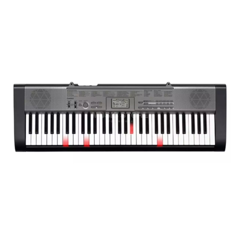
Casio CTK-800 Troubleshooting guide

CONTENTS
Specifications ---------------------------------------------------------------------------------------------- 1
Block Diagram --------------------------------------------------------------------------------------------- 3
Circuit Description --------------------------------------------------------------------------------------- 4
Printed Circuit Board ------------------------------------------------------------------------------------ 5
Disassembly ------------------------------------------------------------------------------------------------ 7
Diagnostic Program------------------------------------------------------------------------------------ 12
Exploded View ------------------------------------------------------------------------------------------- 15
Parts List--------------------------------------------------------------------------------------------------- 16
Schematic Diagrams----------------------------------------------------------------------------------- 19

— 1 —
SPECIFICATIONS
GENERAL
Keyboard: 61 standard-size keys, 5 octaves (with touch response on/off)
Tones: 500 (362 panel tones + 128 General MIDI tones + 10 drum sets); with layer and split
Polyphony: 32 notes maximum (16 for certain tones)
Auto Accompaniment
Rhythm Patterns: 120
Tempo: Variable (226 steps, = 30 to 255)
Chords: 3 fingering methods (CASIO CHORD, FINGERED, FULL RANGE CHORD)
Rhythm Controller: START/STOP, INTRO, NORMAL/NORMAL FILL-IN, VARIATION/ VARIATION FILL-
IN, SYNCHRO/ENDING
Accomp Volume: 0 to 127 (128 steps)
One Touch Presets: Recalls settings for tone, tempo, layer, and split.
<Advanced 3-Step Lesson System>
3-step Lesson: 3 lessons (Step 1, 2, 3)
Playback: Repeat play of a single tune
Evaluation Mode: Scoring 1, Scoring 2, Scoring 3, Phrase Practice
Voice Fingering Guide: On/Off
Song Bank, Piano Bank
Number of Tunes: Song Bank/Sing Along: 50, Piano Bank: 50, download songs: Up to 10
Controllers: PLAY/STOP, PAUSE, FF, REW, LEFT/RIGHT
Musical Information Function:
Tone,AutoAccompaniment, Song Bank, Piano Bank, SingAlong numbers and names;
staff notation, tempo, metronome, measure and beat number, step lesson display,
chord name, fingering, pedal operation, Keyboard, Song Bank icon, Piano Bank icon,
Sing Along icon, Voice Fingering Guide, Evaluation Mode, song memory indicator
Sing Along Mode
Number of Tunes: Song Bank/Sing Along: 50, download songs: Up to 10 (Approximately 70 kilobytes)
Controllers: PLAY/STOP, KEY CONTROL (25 steps, –12 semitones to +12 semitones)
Metronome: On/Off
Beat Specification: 0, 2 to 6
Song Memory
Number of Songs: Two (1 Lesson Recording, 1 Performance Recording)
Recorded Data: Lesson Recording: Right-hand part, left-hand part, both-hand parts
Performance Recording: Track 1 (chord accompaniment), Track 2 (melody)
Recording Method: Real-time
Memory Capacity: Approximately 12,000 notes (total for two songs)
Other Functions
Transpose: 25 steps (–12 semitones to +12 semitones)
Tuning: 101 steps (A4 = approximatery 440Hz ±50Cents)
Terminals
USB port
Sustain/Assignable Jack: Standard jack (sustain, sostenuto, soft, rhythm start/stop)
Headphone/Output Terminal:
Stereo standard jack
Output Impedance: 100Ω
Output Voltage: 4V (RMS) MAX
Microphone In: Standard jack (with microphone volume knob)
Input impedance: 3KΩ
Input sensitivity: 10mV
— 2 —
Power Jack: 9V DC
Power Supply: 2-way
Batteries: 6 D-size batteries
Battery Life: Approximately 9 hours continuous operation on manganese batteries
AC Adaptor: AD-5
Auto Power Off: Turns power off approximately 6 minutes after last key operation. Enabled under batter
power only, can be disabled manually.
Speaker Output: 2.5W + 2.5W
Power Consumption: 9V 7.7W
Dimensions: 96.0 x 37.5 x 14.0 cm (37 13/16 x 14 3/4x 5 1/2inch)
Weight: Approximately 5.4 kg (11.9 lbs)(without batteries)
• Design and specifications are subject to change without notice.
ELECTRICAL
Current drain with 9 V DC:
Consumption Current 650 mA ±20 %
Consumption Current at idle 185 mA ±20 %
with 12 keys from C1 to G2 pressed in 233 SINE LEAD
Volume: maximum, Velocity: maximum
Speaker output level (Vrms with 4 Ωload each channel):
with key D1 in 233 SINE LEAD
Volume: maximun, Velocity: maximum 2020 mV ±20 %
Phone output level (Vrms with 32 Ωload each channel):
with key D1 in 233 SINE LEAD
Volume: maximun, Velocity: maximum 465 mV ±20 %
Output level (Vrms with 47K Ωload each channel):
with key D1 in 233 SINE LEAD
Volume: maximun, Velocity: maximum 2150 mV ±20 %

— 3 —
BLOCK DIAGRAM
RS
R/W
E
LDB4 ~ 7
Keyboard
MAIN PCB
(M706-MDA1)
CONSOLE PCB
(M706-CNA2)
Speakers
(L)
(R)
Main
Volume
CONSOLE PCB
(
M706-CNA1)
SUB PCB
(
M706-PSA1)
AC ADAPTOR
DC 9V
MPU
ML6763B-NNWA-116
IC4
Filter
NJM2068DD
IC3
Power AMP
LA4598-E
IC2
ROM(4MB)
MR27V3202F-TN
IC11
RAM(1M bit)
CY62126DV30LL55ZI
IC12
Phones/
Output
CONSOLE PCB
(M06-CNA3)
Mic Volume
Filter
NJM2068DD
IC1
74AHCT
IC5, 6
MIC
LCD Controller
ST7066U
IC1
Power Supply
Q2 ~ Q4
D4
VD5
(5.3V)
Battery
VC
(9.0V) VCP
(9.0V)
VA5
(5.3V)
Button
MD0 ~ 15
MD0 ~ 15
MA1 ~ 16
MA1 ~ 17
KC0 ~ 7
FI0 ~ 3, SI0 ~ 3
FI4 ~ 7, SI4 ~ 7
Keyboard PCB
(JCM618T-KY1M) Keyboard PCB
(JCM618T-KY2M)
FI8 ~ 10, KI0 ~ 2
KC0 ~ 7
D1

— 4 —
CIRCUIT DESCRIPTION
KEY MATRIX
KC0 KC1 KC2 KC3 KC4 KC5 KC6 KC7
FI0 C21C#21D21D#21E21F21F#21G21
SI0 C22C#22D22D#22E22F22F#22G22
FI1 G#21A21A#21B21C31C#31D31D#31
SI1 G#22A22A#22B22C32C#32D32D#32
FI2 E31F31F#31G31G#31A31A#31B31
SI2 E32F32F#32G32G#32A32A#32B32
FI3 C41C#41D41D#41E41F41F#41G41
SI3 C42C#42D42D#42E42F42F#42G42
FI4 G#41A41A#41B41C51C#51D51D#51
SI4 G#42A42A#42B42C52C#52D52D#52
FI5 E51F51F#51G51G#51A51A#51B51
SI5 E52F52F#52G52G#52A52A#52B52
FI6 C61C#61D61D#61E61F61F#61G61
SI6 C62C#62D62D#62E62F62F#62G62
FI7 G#61A61A#61B61C71
SI7 G#62A62A#62B62C72
F#3 G#3 A#3 C#4 D#4 F#4 G#4 A#4 C#5 D#5 F#5 G#5 A#5
F3 G3 A3 B3 C4 D4 E4 F4 G4 A4 B4 C5 D5 E5 F5 G5 A5 B5 C6
D#3
C2 D2 E2 F2 G2 A2 B2 C3 D3 E3 B6A6G6F6E6D6 C7
C#3A#2G#2
F#2D#2
C#2 A#6
G#6F#6D#6
C#6
NOMENCLATURE OF KEYS
BUTTON MATRIX
KC4
SCORING
3
STEP 2
STEP 3
SCORING
1
LEFT
SCORING
2
KC5
SPLIT
AUTO
HARMONIZE
LAYER
RIGHT
0
–
KC2
PLAY/
STOP
TEMPO씱
SONG
BANK
REW
FF
PAUSE
KC3
TEMPO씰
PIANO
BANK
STEP 1
METRONOME
SPEAK
PRACTICE
PHRASE
KC0
ECHO
PLAY/
STOP
SING
ALONG
KEY CONTROL/
TRANSPOSE
씱
KC1
REVERB/
CHORUS
ONE TOUCH
PRESET
REPERT
KEY CONTROL/
TRANSPOSE
씰
SETTING
SONG
MEMORY
KC6
2
3
+
RHYTHM
4
1
KC7
9
5
6
TONE
7
8
KI0
KI1
KI2
FI8
FI9
FI10

— 5 —
PRINTED CIRCUIT BOARD
MAIN PCB M706-MDA1
Top View
Bottom View
Main PCB M706-MDA1

— 6 —
CONSOLE PCB M706-CNA1
SUB PCB M706-PSA1 CONSOLE PCB M706-CNA2 CONSOLE PCB M706-CNA3 CONSOLE PCB M706-CNA4

— 7 —
DISASSEMBLY
1. Remove the battery cover and then battery.
2. Remove 27 screws and then upper case.
3. Remove two lead wires by soldering.
4. Remove two connectors by soldering.
5. Make the keyboard unit and the main unit apart.
1
3
2
red
black
Connector (CN3)Connector (CN4)

— 8 —
■To remove the main PCB (M706-MD1).
6. Remove three screws on the PCB (M706-MD1).
7. Remove four connectors by soldering.
8. Remove the PCB (M706-MD1).
■Precaution while assembling the main PCB (M706-MD1).
Number of pins on the PCB and pins on the cable are different.
Start connecting from the NO.1 pin whose color is orange.
11 pin cable
CN2 Connector (13pin)
■To remove the sub PCB (M706-PSA1).
9. Remove five screws on the PCB (M706-PSA1).
10. Remove two connectors by soldering.
11. Remove five lead wires by soldering.
12. Remove the PCB (M706-PSA1).
Connector (CN7)
Connector (CN8) Connector (CN2)
Connector (CN1)
Connector (CN9)
Connector (CN3)
Lead wire (orange)
Speaker cord (blue)
Speaker cord (brown)
Speaker cord (green)
Speaker cord (white)

— 9 —
■To remove the console PCB (M706-CNA1, CNA2, CNA3).
13. Remove the microphone and the volume knob.
14. Remove two screws on the PCB (M706-CNA2).
15. Remove three screws on the PCB (M706-CNA3).
16. Remove 30 screws and then the PCB (M706-CNA1).
Caution while assembling: 6 screws fixing the LCD unit are different size from other screws.
Fixing with incorrect size of screws causes the risk of defective displaying.
Be sure to choose correct screws.
17. Remove the rubber keys.
■To remove the speaker.
18. Remove 8 screws and then two speakers.
Note: Fix speaker cords securely.

— 10 —
■To remove the key PCB (CSM618T-KY1M, KY2M)
19. Remove 13 screws and the bottom case.
Projection
Note: Tighten the screw with the arrow mark in the figure first when reassembling.
20. Remove 19 screws and then the key PCB (CSM618T-KY1M, KY2M).
21. Remove the rubber keys.
Note: Pay attention to the positions of the rubber keys
as one of them has a different length. Match
the projections of the rubber keys with the holes
of the lower case when reassembling.

— 11 —
Note: Pay attention to the positions of the screw
holes when reassembling.
23. Remove the black keys.
22. Remove 21 screws and then the white keys.

— 12 —
DIAGNOSTIC PROGRAM
■Initial Setting
1. Connect the AC adaptor.
2. Connect a Sustain pedal.
3. "MODE" switch: NORMAL
4. "Main" volume: MAX
NOTE: If there is no Sustain pedal, Sustain pedal check can be skipped.
■How to start diagnostic program
1. Press the “POWER” button while pressing the “0” buttons.
2. The massage “TST” is displayed on LCD.
3. Release the “0” button.
■Diagnostic program Message on LCD
1. Button check
1Press “0” button. 00
* Wait for confirmation sound.
2Slide switches or press buttons in the order from No.01 to No.2E. BUTTON NO.
NOTE: The button numbers are written in hexadecimal numerals.
3Press the “SPLIT” button the last. COK
*Wait for confirmation sound.
*The Button number appears on the LCD. BUTTON NO.
*A buzzer sounds if buttons are pressed in a wrong order, and "CER" appears on LCD.
NOTE: This check cannot be aborted in mid-course.
2. AC adaptor check
1Press “-” button. JOK
3. RAM check
1Press “+” button. AOK
4. Pedal check
1Press “1” button. TCH
2“Sustain pedal”: ON SUS
3“Sustain pedal”: OFF
5. ROM check
1Press “2” button. OOK
00
01
02
03
04
05 06 07 08 09
0A 0B
0C 0D 0E 0F 10 11 12 13 14 15
18
16 17
1A 191B
1C 1D 1E 1F
20
21 22
23
24
25
29
28
27
26
2A
2B
2C
2ECOK
2D

— 13 —
Message on LCD
6. Version check
1Press “3”button. 706
2Press “3”button. 350
3Press “3”button. 340
7. Sound check
1Press the “4”button. MIN
*When standing in the center, the tester hears the minimum test sound in an equal
volume from both right and left speakers.
2Press the “5”button. MID
*When standing in the center, the tester hears the medium test sound in an equal
volume from both right and left speakers.
3Press the “6”button. MAX
*When standing in the center, the tester hears the maximum test sound in an equal
volume from both right and left speakers.
4Press the "7" button. L
*When standing in the center, the tester hears the maximum test sound fromthe left
speaker.
5Press the "8" button. R
*When standing in the center, the
tester
hears the maximum test sound from the right
speaker.
8. LCD check
1Press the “STEP1”button.
* All character of LCD turns on.
* There is no lack of the dot and the character.
2Press the “STEP2”button.
* Half dots on DP3 area of LCD turns on.
* There is no lack of the dot and the character.
3Press the “STEP2”button.
* Another half dots on DP3 area of LCD turns on.
* There is no lack of the dot and the character.
4Press the “STEP3”button.
* Half segments of LCD turns on exclude DP3.
* There is no lack of the dot and the character.
5Press the “STEP3”button.
* Another half segments of LCD turns on exclude DP3.
* There is no lack of the dot and the character.
6Press the “LEFT”button.
* Block of LCD turns on by sequential.
* There is no lack of the dot and the character.
7Press the “SCORING1”button.
* 1 octave white keys and black keys of LCD turns on by sequential.
* There is no lack of the dot and the character.

— 14 —
9. Console LED check
1Press the “SPEAK”button.
* Keyboard LED must light in the undermentioned order.
1) DATAACCESS
2) PLAY/STOP
3) START/STOP
10.APO check
1Press the “PRACTICE PHRASE”button.
* Go out from TEST mode (Power off).
* The LCD turns off.
DIAGNOSTIC PROGRAM IS FINISHED.

– 15 –
EXPLODED VIEW
R-1
24
25
28
30
39
39
16
3
2
1
CNA3
CNA2
CNA1
CNA4
21
31
13
33
3534
19
17
23
22
26
27
29
7
8
38
6
5
14
R-2
R-3
9
12
11
10
15
18
36
32
41
40

—16 —
Notes: This parts list does not include the cosmetic parts,
which parts are marked with item No. "R-X" in the
exploded view.
Contact our spare parts department if you need
these parts for refurbish.
1. Prices and specifications are subject to change
without prior notice.
2. As for spare parts order and supply, refer to the
"GUIDEBOOK for Spare parts Supply",
published seperately.
3. The numbers in item column correspond to the
same numbers in drawing.
PARTS LIST
CTK-800

—17 —
N Item Parts Code Parts Name Specification QTY Price
Code R Remarks
Main PCB
N 1 10203305 PCB ASSY/MAIN TK-RJM505831*001 1 A
IC1
10197809 IC TC7WH123FU
(
TE12 .F 1 C
IC2
10158804 IC R1154H033B-T1-FB 1 C
N
IC3
10158805 IC RH5R 33AA-T1-FA 1 C
N
IC5,6,13,14
10116986 IC SN74AHCT1G08DCKR 4 C
IC7
10197555 IC TC7SZ14FU
(
TE85 .F
)
1C
N
IC8
10159723 IC RN5VD28AA-TR-FA 1 C
IC10
10197554 IC TC7SZ126FU
(
TE85 .F 1 C
N
IC12
10199777 MEMORY CY62126DV30 55ZXI 1 C
Q2,3,4
10116461 TRANSISTOR KTC4075GR-RTK 3 C
Q5,6
10154941 TRANSISTOR KTA2014GR-RTK 2 C
N
Q7
10153685 TRANSISTOR 2SJ346
(
TE85 .F
)
1C
D1-3
10009218 DIODE 1SS400TE61 3 C
X1
10133372 RESONATOR SMD-49-12M 1 X
F1,2,,8,9,12
10122976 NETWORK/R-C EZASTB63ABJ 5 B
F3-7,10,11
10122975 NETWORK/R-C EZASSB516BJ 7 B
2-5,7,8,9
10095204 COI B M18AG102SN1D 7 X
6
10158809 COI D P31SN221S 2 1 X
1
10122963 COI B M21AG102SN1D 1 X
CN5
10162810 CONNECTOR UBR27-4K9G00 1 X
Sub PCB
N 2 10203306 PCB ASSY/PSA1 TK-RJM505832*001 1 B
IC1,3
21210072 IC NJM2068D-D 2 C
IC2
10190010 IC A4598-E 1 C
Q1-3
10079927 TRANSISTOR KTC3199GR-AT 3 C
Q4
10085192 TRANSISTOR KTC2026Y 1 C
Q2
10079926 TRANSISTOR KTA1273Y-AT 1 C
D2
10080347 DIODE 1A2TA 1 C
D3
10079928 DIODE 1SS133TA 1 C
N
D4
10162757 DIODE/ZENER DZ6.2BSATA 1 C
D1
10079929 DIODE/ZENER SRT14TA 1 X
N
J3
10161308 CONNECTOR DJ-0702O-015 1 X
J4
69325081 CONNECTOR JY-6314-01-030 1 X
J1
69325358 CONNECTOR JY-6314-01-130 1 X
J2
69325082 CONNECTOR JY-6316-01-070 1 X
2
10057360 COI R2318-RB53-856396 1 C
1,3
10056228 COI R2318-RB53-856397 2 C
Console PCB
N 3 10203307 PCB ASSY/CAN TK-RJM505835*001 1 C
IC1
10143126 SI ST7066U-0A-Q 1 C
TH1
10080368 THERMISTOR MF11-103K 1 C
D8-15
23901344 DIODE 1SS133T-77 8 C
D3
10106131 ED 1154HD-B5/6-90 1 C
N
D7
10203864 ED 1154HD-B5/7.5-90 1 C
VR1
27652213 VARIAB E RESISTOR RS20H121-2KB 1 C
N
VR3
10174471 VARIAB E RESISTOR RK09K1130D48 1 C
N
VR2
69304870 VARIAB E RESISTOR EVND8AA03B53 1 C
Notes : Q- Quantity per unit
R- Rank

—18 —
N Item Parts Code Parts Name Specification QTY Price
Code R Remarks
Ke
y
board PCBs
5 10053891 PCB ASSY/KY1M M140687*9 1 C
D501 - D564
23010101 DIODE 1S2473T-77-T 64 X
6 10053893 PCB ASSY/KY2M M140688*9 1 C
D565 - D622
23010101 DIODE 1S2473T-77-T 58 X
Ke
y
board Unit
7 69222720 KEY SET/ T WHITE M312118*1 4 C
8 69222730 KEY SET/ T WHITE M312118*2 1 C
9 69068481 KEY SET/ T B ACK 10P M140369A-3 2 C
10 69068591 KEY SET/ T B ACK 5P M140369A-4 1 C
11 69222762 RUBBER/CONTACT M211704B-1 4 B
12 69222772 RUBBER/CONTACT M211705B-1 1 B
Case Unit
N 13 10199878 REF ECTOR RJM505455-001V01 1 C
N 14 10203310 COVER ASSY/BATTERY TK-M341235*003 1 C
15 69273030 PACKING M440775-1 2 C
16 10116376 ED S R343BBT3F 2 C
N 17 10199865 P ATE/DISP AY RJM505452-001V01 1 C
18 10199714 KNOB/S IDE RJM503803-002V01 2 C
N 19 10197646 KNOB/ROTARY RJM502503-010V01 1 C
N 21 10199866 RUBBER KEY/A RJM505441-001V01 1 C
N 22 10199867 RUBBER KEY/B RJM505442-001V01 1 C
N 23 10199868 RUBBER KEY/C RJM505443-001V01 1 C
N 24 10199869 RUBBER KEY/D RJM505444-001V01 1 C
N 25 10199870 RUBBER KEY/E RJM505445-001V01 1 C
N 26 10199871 RUBBER KEY/F RJM505446-001V01 1 C
N 27 10199872 RUBBER KEY/G RJM505447-001V01 1 C
N 28 10199873 RUBBER KEY/H RJM505448-001V01 1 C
N 29 10199874 RUBBER KEY/J RJM505449-001V01 1 C
N 30 10199875 RUBBER KEY/K RJM505450-001V01 1 C
31 69270510 SWITCH/S IDE KNOB CSB-08D 1 C
N 32 10199877 CD TR4363N 1 C
N 33 10199879 P ATE/B RJM505456-001V01 1 C
N 34 10199881 TOP PIECE RJM505457-001V01 1 C
N 35 10199880 FI M RJM505454-001V01 1 C
N 36 10199876 CONNECTOR RJM505453-001V01 2 C
38 69224480 DUMPER/KEY M412324-1 1 C
39 38311096 SPEAKER S12J89A 2 C
40 69032150 SPRING/BATTERY
(
+
)
M41330-1 1 C
41 69026141 SPRING/BATTERY
(
-
)
M41226A-1 1 C
Accessories
- 10107083 STAND/MUSIC M141071-5 1 C
- 69321739 BATTERY R20PNR/2SK 3 C
N - 10199852 ABE /RATING M341007-053V01 1 X
- 10197572 CD ROM USB12CDROMW 1B 1 C
Refurbish
N R-1 10203308 CASE ASSY/UPPER TK-RJM505748*001 1 C
R-2 10086645 CASE ASSY/MIDD E M141274*008 1 C
R-3 69069252 P ATE/BOTTOM M240573-2 1 C
Notes : Q- Quantity per unit
R- Rank
Table of contents
Other Casio Musical Instrument manuals

Casio
Casio Privia PX-720 User manual

Casio
Casio CDP-S105 User manual

Casio
Casio Privia PX-765 User manual

Casio
Casio CDP-240R User manual

Casio
Casio PRIVIA PX-135 User manual

Casio
Casio RAP-1 User manual

Casio
Casio MT-640 User manual

Casio
Casio Privia PX-400R Installation instructions

Casio
Casio LK-170 User manual

Casio
Casio Casiotone MT-400V User manual

Casio
Casio CTK-100 User manual

Casio
Casio Privia PX-700 User manual

Casio
Casio CTK-2080 User manual

Casio
Casio Casiotone MT-520 User manual

Casio
Casio CTK-520L User manual

Casio
Casio TONEBANK MT-750 User manual

Casio
Casio DM-100 User manual

Casio
Casio Celviano AP-80R User manual

Casio
Casio Privia PX-S6000 User manual

Casio
Casio CDP-S360 User manual