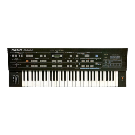
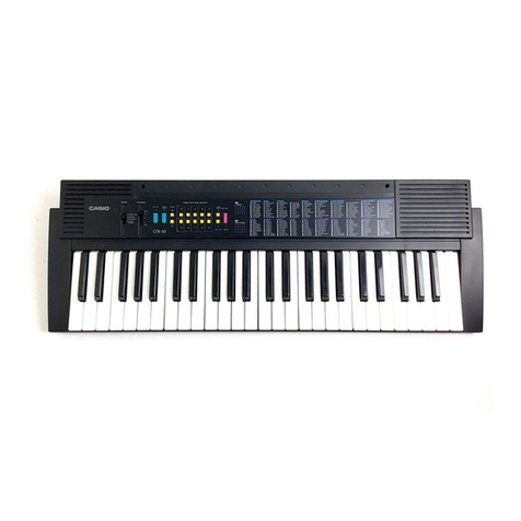
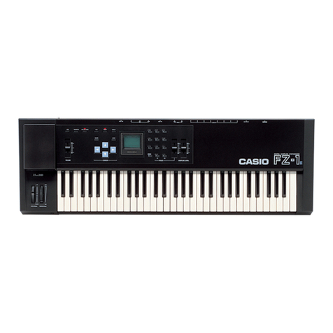
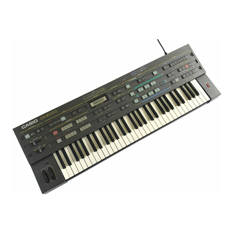
Casio CZ-1000 User manual


Contents
About the Power Supply 3
Name and Function of Each Part 5
Connections With External Equipment 12
How to Create Sounds with the CZ-1000 13
•PD Sound Source 13
•Envelopes 14
•Block Structure 15
Programmer Section 19
•Preset Tones 19
•Internal Memory Tones 19
•Cartridge Memory 20
•Compare/Recall Key 20
Write/Save/Load 22
Parameter Section 25
•Wave Form 25
•Envelope Settings ...26
•DCW Key Follow 29
•DCA Key Follow 29
•Vibrato 30
•Octave 31
•Detune 31
•Line Select 32
•Ring Modulation 32
•Noise Modulation 32
•Initialize 33
Effect Section 34
•Bend Range 34
•Vibrato 34
•Portamento 34
•Solo key 35
•Tone Mix 35
•Key Transpose 36
MIDI 37
Care of Your Unit 41
Specifications 42

About the Power Supply
The CZ-1000 can use three kinds of power supplies —dry batteries, household electricity or a
car battery.
(a) Dry Batteries
The CZ- 1000 uses 6D-size manganese dry batteries.
Inserting the batteries >
Remove the lid of the battery compartment on the
bottom of the unit and insert the batteries taking
care not to confuse ©and ©.Always replace all 6
batteries at the same time as this will help length-
en battery life.
After having inserted batteries for the first time,
be sure to press the "P" button. (Refer to the ex-
planation of the Pbutton below.)
<Bottom of the CZ-1000 >
Battery compartment
battery
Pbutton
HEE 'j
IInrirt" -ra—
i
Battery compartment lid
About the Pbutton
In order to clear any bugs (software malfunctions) that can occur in
the memory during battery replacement, be sure to press the Pbut-
ton with apointed object 0after you have inserted batteries for the
first time, and @after you have inserted new batteries when the time
that has elapsed since removal of the old batteries is more than 10
minutes. Pressing the Pbutton causes the 16 sounds set in the inter-
nal memory before shipment to be recalled. At the same time, any
new tones you have set in the internal memory will be cancelled, so
please be careful.
®
Pbutton
*Be sure to press the Pbutton when power is turned ON, otherwise it will have no effect.
Battery life is about 5hours in the case of high-performance types (SCJM-1). When the bat-
teries begin to wear out, the power indicator will start to flash. If this occurs, please replace
all 6dry batteries with new ones as soon as possible. ——
(b) Household electricity
*You can use household electricity as a power supply for the CZ -1000 by connecting the special
AC adaptor (AD-5, optional).
By connecting the special car
from your car's cigar lighter,
Right part of the CZ-1000 >Household power
supply
Power supply terminal //]Car adaptor

*Even when using household electricity or acar battery, be sure that dry batteries are also
inserted at the same time in order to protect the memory data.
*When connecting or unplugging an adaptor, please be sure to turn off the power
beforehand.
*If you do not intend to use your instrument for longer periods, please remove the dry bat-
teries in order to avoid damage due to battery leakage.
*Please be sure to use only the specified AC or car adaptors. Any damage caused by the
use of other adaptors is not covered by the warrantee.
*If an adaptor is used for any length of time, the adaptor itself will heat up somewhat, but
this is no cause for alarm. However, do unplug the adaptor from the wall receptacle or
the cigar lighter when not using it.
*Concerning protection of the memory contents
The tone data entered into the internal memory or another will be backed up by the inserted
batteries and not be cancelled even if the power switch is turned off when an AC adaptor or
car adaptor is connected as well as during use of aDC power supply (dry batteries). If, however,
no batteries are inserted or the inserted batteries are already spent, the memory contents may
be erased or altered, so please be careful.
*The memory contents will not be erased during battery replacement if the new batteries are
inserted within 10 minutes after the old ones have been removed. Therefore please insert 6
new batteries within this space of time.
*Battery life is about 12 months in case of using the battery only for protecting memories.
Auto-Power-Off function
APO
OFF ON
When the APO (Auto-Power-Off) switch is set to ON
This function automatically turns power off approximately 6minutes after
the last operation was performed in order to avoid unnecessary power con-
sumption. If this has happened, set the power switch to OFF and then turn
the power on again by setting it back to ON.
When the APO (Auto-Power-Off) switch is set to OFF
Setting the APO switch to OFF cancels the Auto Power Off function explained
above.
When you use this instrument while the power indicator has started to flash due to weaken-
ing of the batteries, the power will turn off automatically just before the data in the internal
memory is erased in order to protect this data, regardless of whether the APO switch is set
to ON or OFF. When this happens, stop using the instrument and immediately replace the
used batteries with new ones.
,_____
The types of data protected by battery back-up even when power is turned off are as follows.
•Internal memory tone data
•Tone data in the compare/recall area
•Master tune
•Key transpose
•Bend range
•Portamento time
•Tone numbers and levels of the Tone Mix function

Name and Function of Each Part
VOLUME
EFFECT section (7) PROGRAMMER section
LC display
\
ilO
VOLUME 'TEFFECT TT" PROGRAMMER
BEND RANGE VIBRATO
ON/OFF PRESET INTERNAL CARTRIDGE MEMORY
CD H3
1IP P P P
P
10 111 |12 |13 114
MONO SOLO TONE MIX KEY TRANSPOSE
2Z*WRITE MIDI
z.
JflUE Sgl
IRTE=&72J
DIGITAL S^B—
f\ [~L A_ AA
WAVE
IRSOI
VII A
SAVE LOAD
DATA, __
PITCH BEND
Im\wm
®PITCH BEND @MIDI key
©WRITE key
®KEY TRANSPOSE key
TONE MIX key
4) SOLO key

DATA ENTRY section ®PARAMETER section MASTER TUNE
213I4
VIBRATO WAVE m
IZER
,CURSOR —
-DEE
DOWN UP
—ENV POINT
-
SUSTAIN END
—INITIALIZE —
PARAMETER
-DcoLtl ——-tdcwQ] «.dcaQ)
WAVE FORM ENV KEY FOLLOW ENV KEY FOLLOW ENV
^—.DCOl DCWH DCA[2] —
rMASTER TUNEi
JDETUNE L. [2] LINE SELECT
RING NOISE-
cd C3 ,
•—MODULATION —
'
POWER
1
KEYBOARD POWER switch
POWER indicator-

©PITCH BEND
By rotating this wheel, you can control the pitch within the variable range set with the Bend
Range parameter in the Effects section.
©VOLUME control
This control allows you to adjust the output level appearing at the line out terminal as well
as the headphone volume.
®EFFECT section
Indicator -
BEND RANGE key-
VIBRATO ON/OFF key-
Indicator -
TIME setting key-
PORTAMENTO ON/OFF key-
EFFECT
BEND RANGE VIBRATO
ON/OFF
TIME ON/OFF
-PORTAMENTO—
SOLO key
TONE MIX key
KEY TRANSPOSE key
MONO SOLO TONE MIX KEY TRANSPOSE
BEND RANGE key
Press this button to set the variable range of the pitch bend. Data entry itself is performed in
the Data Entry section.
VIBRATO ON/OFF key
This key is used to switch the vibrato effect on and off. When this effect is on, the indicator is lit.
*When the vibrato depth is "00", the indicator turns off automatically and this key does not
operate.
PORTAMENTO ON/OFF key
This key switches the portamento effect on and off. When this effect is on, the indicator is lit.
TIME setting key
This key is pressed when you want to set the portamento time. Data entry itself is performed
in the Data Entry section.
®SOLO key
Press this key when you want monophonic sound. The indicator is lit when the Solo effect is on.
©TONE MIX key
Press this key when you want to mix two tones which will then sound simultaneously. The indi-
cator is lit when this function is on. (The keyboard will be switched to monophonic.)
©KEY TRANSPOSE key
Press this key when you want to use the Transpose function. Setting of the keyboard pitch is
performed using and the Data Entry section.

®PROGRAMMER section
®®9
PROGRAMMER
PRESET INTERNAL CARTRIDGE MEMORY COMPARE
/RECALL
,SELECT key
®PRESET key
Press this key when you want to recall one of the preset tones from the memory. When the
preset tone mode is selected, the indicator lights up.
®INTERNAL MEMORY key
This key is used when you want to recall atone from the internal memory or when you would
like to store anew tone in the internal memory. When the internal memory mode is selected,
the indicator lights up.
©CARTRIDGE MEMORY key
When you want to memorize atone in the optional RAM cartridge or recall atone from the
cartridge memory, press this key. When the cartridge memory mode is selected, the indicator
lights up.
®COMPARE/RECALL key
When you have altered atone recalled from amemory using the Parameter section and Data
Entry section, you can compare it with the previous tone (the one before the alterations were
made) by pressing this key. Pressing it once selects the previous tone, pressing it once again
selects the altered tone.
When atone has been altered, the indicator of this key automatically lights up, showing that
the selected sound is being changed.
©TONE selectors
These keys are used to recall the 16 individual tones from each of the memories ®,©and ©
.
When atone is selected, the respective indicator lights up. When the SELECT key is on (its
indicator is lit), pressing the tone selectors will select tones with numbers from 9to 16.

(DDATA ENTRY section
r=?/:=; Ft
UfiUE FORM
FIRST=2'SEC0ND=5
DIGITAL SYNTHESIZER I
1
K2
n_ 3
A_ 456
mniu.
7a
ilk.
WAVE FORM
-VALUE --CURSOR-
-Set value
Liquid Crystal
"Display (=LCD)
-Cursor
LOAD
DATA ENTRY
®®®
©J&key
Press this key when you want to save an internal memory tone in aRAM cartridge. Also use
this key to set the tone data shown on the LCD (=Liquid Crystal Display). Each time this key
is pressed, the value will decrease by 1. Keeping the key depressed causes acontinuous decrease
of the value.
©Sokey
Press this key when you want to load aRAM cartridge tone into the internal memory. Also use
this key to set the tone data shown on the LCD (=Liquid Crystal Display). Each time this
key is pressed, the value will increase by 1, Keeping the key depressed causes acontinuous
increase of the value.
©LU key/® ©key
Use these keys to move the cursor on the LCD (=Liquid Crystal Display) which indicates the
tone data being set. Pressing the S3 key moves the cursor the left, pressing the OS key moves
it to the right.
®PARAMETER section
®0(R) ©®®

®ffl key/® $key
Use these keys to select the step number for each envelope (DCOl, DCW1, DCA1, DC02,
DCW2 and DCA2 envelope). Each time the Skey is pressed, the step number will decrease
by one. Each time the g1key is pressed, the step number will increase by one.
©SUSTAIN key
Press this key to set the sustain point for each envelope. Pressing the key again releases the
sustain point setting mode.
@END key
Press this key to set the end point for each envelope. Pressing the key again releases the
end point setting mode.
©INITIAILIZE key
Pressing this key initializes the settings of the various parameters (sets the respective data
to 0), thus making it easier to start creating sounds right from the beginning. To use this
function, press the INITIALIZE key and then simultaneously press the key of the parameter
you want to change.
©VIBRATO key
Press this key when you want to set the vibrato effect independently for each tone. Data set-
ting itself is performed in the Data Entry section.
®OCTAVE key
Pressing this key lets you shift the pitch range of each tone up or down in one octave steps.
Data setting itself is performed in the Data Entry section.
®WAVE FORM key
Press this key when you want to select the basic wave form for Line 1. When this key is set
to on, its indicator lights up.
©DCO envelope key
This key lets you set the pitch envelope for Line 1. When this key is selected, its indicator
lights up.
®DCW KEY FOLLOW key
Press this key when you want to make the wave form of the Line 1DCW approach apure
sine wave according to the pitch of the keys being played.
®DCW envelope key
Press this key when you want to set the wave envelope for Line 1. When this key is selected,
its indicator lights up.
0DCA KEY FOLLOW key
Use this key when you want to effect temporal changes in the envelope level of the Line 1DCA.
©DCA envelope key
Press this key when you want to set the parameters of the Line 1amplifier envelope. When
this key is selected, its indicator lights up.
®WAVE FORM key
Press this key when you want to select the basic wave form for Line 2. When this key is set
to on, its indicator lights up.
©DCO envelope key
This key lets you set the pitch envelope for Line 2. When this key is selected, its indicator
lights up.
-to-

®DCW KEY FOLLOW key
Press this key when you want to make the wave form of the Line 2DCW approach apure
sine wave according to the pitch of the keys being played.
©DCW envelope key
Press this key when you want to set the wave envelope for Line 2. When this key is selected,
its indicator lights up.
(?) DCA KEY FOLLOW key
Use this key when you want to effect temporal changes in the envelope level of the Line
2DCA.
©DCA envelope key
Press this key when you want to set the parameters of the Line 2amplifier envelope. When
this key is selected, its indicator lights up.
®DETUNE key
Pressing this key detunes the pitch of Line 1or Line 2without changing the tone, so you
get Line Vor Line 2'.
®RING MODULATION key
Pressing this key causes Line Vor Line 2' to be ring modulated by Line 1. When this key
is selected, its indicator lights up.
®NOISE key
Pressing this key causes Line Vor Line 2' to be modulated by noise. When this key is select-
ed, its indicator lights up.
®LINE SELECT key
This key allows you to select aline depending on the type of sound you want to create and
to combine the lines as you wish. Pressing the key changes line selection in the
order Qj -* [H -» 11 +Tl -> 11 +21 and so on. The indicator above the selected line combi-
nation lights up.
©MASTER TUNE keys
These keys are used to change the pitch of the entire keyboard.
©WRITE key
Use this key when you v/ant to store a newly created sound in the internal memory or in an
optional RAM cartridge, when you want to save an internal memory tone in the RAM cartridge,
or when you want to load atone from the RAM cartridge into the internal memory.
©MIDI key
Pressing this keys sets the CZ- 1000 to MIDI data communication mode allowing data transfer
to and reception from other units connected via MIDI cable.
•//•

Connections With External Equipment
•Back of instrument
®® ®
•Right side of instrument
h«
9V PMCUTS LINE
® ® ® ®
•Bottom of instrument
f
Battery compartment lid (J)
®Cartridge insertion slot
Insert aRAM cartridge (optional) here. ARAM
cartridge is capable of storing, the data for 16
tones.
©PROTECT switch
In order to avoid accidental erasure of inter-
nal memory or cartridge memory contents
(tones), the CZ-1000 is equipped with a
memory protect function. When the PRO-
TECT switch is set to ON, the memory is pro-
tected, meaning that you cannot memorize
new tone data or save and load data between
the internal memory and the cartridge
memory. These operations can only be per-
formed when the PROTECT switch is set to
OFF. (See page 22 for details.)
(3) MIDI Input/Output terminals
Use the terminal for connection of the
CZ-1000 to other keyboards, personal com-
puters, etc. provided with MIDI terminals.
®APO (Auto Power Off) switch
When the APO switch is set to ON, the Auto
Power Off function operates to avoid unneces-
sary power consumption. To cancel this func-
tion, set the APO switch to OFF. (See page
4for details.)
®Power teminal
Connect an AC adaptor (optional) or acar
adaptor (optional) here.
©Headphone jack
When using headphones to monitor the
sound of the CZ- 1000, connect them to this
jack.
©Output jack
Connect this jack to your stereo, to akey-
board amplifier or mixer, etc.
®P button
Press this button when you want to recall the
original internal memory tones or clear any
bugs. (See page 3for details)

How to Create Sounds with the CZ-1000
•PD (Phase Distortion) sound source
The CZ- 1000 uses the unique PD (Phase Distortion) sound source system developed by CASIO.
As the words "phase distortion" indicate, this system distorts the phase angle of asine wave or
cosine wave written into aROM when read, thus creating avariety of wave forms. The pattern of
the distorted reading phase angle determines the DCO (corresponds to the VCO in an analog syn-
thesizer) wave form. The amount of distortion of the reading phase angle (depth of modulation)
is determined by the momentary value of the DCW envelope (which corresponds to the VCF of
an analog synthesizer).
(Fig. l)
Fig. 1shows what happens when the phase angle of
the cosine wave written into the ROM is read in linear
form—the cosine wave is output as it is.
The phase angle is read at afixed speed, taking on
values from 0to 2x.
Next, let us see what happens when the reading speed
from 0to 7r is speeded up while the reading speed
from xto 2xis slowed down.
(To make the explanation easier to understand,
the polarity of the cosine wave cos 0has been
inverted.)
(Fig. 2) As shown in Fig. 2, the reading of the phase angle
is now no longer linear but distorted, while the out-
put cosine wave has become similar to asaw-tooth
wave.
What happened if we then make the reading speed
from 0to xfaster than before and further slow down
the reading speed from xto 2 x?
As you can see in Fig. 3, the output cosine wave is
now an almost perfect saw-tooth wave.
This PD sound source system can thus easily output
all kinds of wave forms other than acosine wave by
simply distorting the reading phase angle of acosine
wave (or sine wave) stored in aROM. This unique
Phase Distortion system, which can modulate cosine
waves, thus proves to be atruly revolutionary sound
source.

Figures 1to 3showed the kind of reading phase angle distortion pattern that occurs when the
phase angle reading speed from 0to it is accelerated while the phase angle reading speed from
7r to 27r is slowed down. Apattern such as this is created when the saw-tooth wave form is selected
with the DCO Wave Form parameter.
If adifferent kind of wave form is selected with the DCO Wave Form parameter, the reading phase
angle is distorted to that respective pattern. The CZ- 1000 can thus output awhole variety of wave
forms.
The intensity of the reading phase angle distortion is controlled by the DCW envelope's momen-
tary value, meaning that it can be changed over time. If the DCW envelope is set as shown in Fig.
4, an undistorted cosine wave is output at point ®,while distortion is at its maximum at point
©so that asaw-tooth wave is output as shown in Fig. 3. At point ©,distortion has become less
(meaning the intensity of the modulation has decreased), so that awave form is output that lies
somewhere between the kind of cosine wave shown in Fig. 2and aperfect saw-tooth wave.
(Fig. 4) Points to remember:
DCW envelope
Key ON Key OFF
1) The pattern of the reading phase angle distortion
corresponds to the wave form selected with the
DCO WAVE FORM parameter.
2) The amount of reading phase angle distortion (in-
tensity or depth of modulation) is determined by
the momentary value of the DCW envelope.
•Envelopes
The CZ -1000 has independent envelope generators for each of the two DCO/DCW/DCA systems.
The envelopes generated by these envelope generators control the changes in pitch, tone color
and sound volume over time. The envelope generators of the CZ-1000 let you set complex enve-
lopes with up to 8steps. In addition, the Sustain Point (which determines the level at which a
sound is held as long as akey is being pressed) can be set at will. This means that you have much
more freedom than with conventional envelope generators limited to ADSR (see below), giving
you infinite possibilities for sound creation.
(Fig. 1)
Fig. 1shows an example of an envelope using all 8
steps. In this example, there are two attacks before
the Sustain Point as well as athird attack after releas-
ing the keys. This shows how you even have the pos-
sibility of setting an "after-envelope".
Key ON Key OFF END Step
Rn and Ln (n =1to 8) indicate the rate (speed of level change, "slope") and level (final level reached
in astep) respectively. Within aparticular envelope, the level Ln is reached after the slope Rn to
complete step n. Following the arrival at Ln, step n+1begins (with slope Rn+i). The only excep-
tion is the step in which the Sustain Point has been set, which is step 5in our example in Fig.
1. During this step, the sustain level (the level set for the step containing the sustain point) will
be held as long as akey is being pressed, without moving on to the next step. As soon as the
key is released, the following envelope step will commence with the corresponding slope (rate).
Fig. 1shows an example of an envelope making use of all 8steps. Of course, it is up to you how
many steps you want to use.

(Fig. 2) (Fig. 3)
Key ON
R,/ t
SUSTAIN
Point
CZ-1000
i
Key OFF END Point
Conventional analog synthesizers
With conventional analog synthesizers, an envelope is usually set according to 4parameters —
attack time, decay time, sustain level and release time. This is what is called an "ADSR" type enve-
lope (ADSR being the initial letters of the 4parameters) as shown in Fig. 3. In order to set an
ADSR envelope with the CZ-1000's envelope generator, you only have to use 3steps. (Fig. 2)
Block Structure
(Fig. 1)
—>dcoh] --DCWHJ' DCAQ]
WAVE FORM ENV KEY FOLLOW ENV KEY FOLLOW ENV
^DETUNE
WAVE FORM ENV KEY FOLLOW ENV KEY FOLLOW ENV
DCO[U —*DCWH] —>DCA(2] —
ffl
a
®®
The CZ- 1000 has two sound generation lines, each consisting of DCO, DCW and DCA. The sound
from each of these two lines can be output either directly or in adetuned form (with adifferent
pitch). This means that in effect the structure of the CZ -1000 sound generation system offers 4
lines. (Fig. 1)
The line directly output from DCO 1 is called Line 1(HI), the detuned output Line V(HI). In
the same manner, the line directly output from DCO 2is called Line 2(ffl ), the detuned output
Line 2' (\Z\ ).

The following is abrief explanation of the various parts of Fig. 1.
©Digital Controlled Oscillators (DCO 1, DCO 2)
The Digital Controlled Oscillators correspond to the VCOs (Voltage Controlled Oscillators) used
in analog synthesizers. As parameters, the DCOs have Wave Form and Envelope Generator
parameters. These parameters select the basic wave form (Wave Form) and control the changes
in pitch over time after akey has been pressed.
As shown in Fig. a, you can choose from 8kinds of basic wave forms (from SAW-TOOTH to
RESONANCE) as well as being able to combine any two* of these wave forms to create wave
forms such as those shown in Fig. b. This means that altogether, you have aselection of 33
wave forms to choose from according to the sound you want to create.
(Fig. a) K'IT_ 3A_ .AA
SAW-TOOTH SQUARE PULSE DOUBLE SINE
5. (\- 6nitons 7jiIl
SAW- PULSE RESONANCE IRESONANCE II RESONANCE III
(SAW-TOOTH) (TRIANGLE) (TRAPEZOID)
(Fig. b)
KTL
rLk.-
—combination of saw-tooth and square waves
combination of saw-pulse and resonance Iwaves
Except the resonance wave forms from 6to 8, which cannot be combined.
The change of pitch over time is controlled by the envelope generator. This means that the
pitch changes according to the rate (slope) and level (final level in astep) that have been set
for each step.
P(Pitch)
*At the End Point Ls, the level becomes 0.
R3
L3
\
|\R«
SUSTAIN Point
!
Key ON Key OFF |t(time)
END Point
-16-

)Digital Controlled Wave (DCW 1, DCW 2)
The Diqital Controlled Wave section corresponds to an analog synthesizer's VCF (Voltage Con-
trolled Filter) The parameters of this section are Key Follow and Envelope Generator parameters.
Key Follow controls the wave form according to the pitch of the keys being played, while Enve-
lope parameters control the change over time of the wave form after akey has been pressed.
The Key Follow parameter has the function of making the wave form gradually approach apure
sine wave (or cosine wave) the higher the pitch of the key being pressed. It can be set to one
of 9different levels. (Fig. 1)
(Fig. l)
ffllfflfflli!!
[\ Approaches the sine wave form
The chanqe of the wave form over time is controlled by the envelope generator. The wave form
depends on the momentary value of the envelope. With the PD system, the change is performed
starting with apure sine wave and ending with the basic wave form set in the DCO section.
(Fig. 2)
DCW envelope
r\f\f\
Key OFF
Key ON
If one of the basic resonance wave forms Ito III has been selected in the DCO section, the num-
ber of sine waves (that is to say, the sine wave frequency) within one of the window wave forms
K/\ r\ is altered between 1and 16 according to the momentary value of the envelope
achievinq the same effect as if the resonance level of the VCF in an analog synthesizer had
been raised. This is very effective when you want to accentuate aparticular frequency range.
(See Fig. 3.)
(Fig. 3)
DCW ENVELOPE
When using resonance II
Key ON Key OFF

(D Digital Controlled Amplifiers (DCA 1, DCA 2)
The Digital Controlled Amplifiers correspond to the VCA (Voltage Controlled Amplifier) in an
analog synthesizer. As parameters, the DCAs use Key Follow and Envelope Generator parameters.
Key Follow controls the duration of the envelope's effect according to the pitch of the keys be-
ing played, while the Envelope parameters control the change in volume over time when akey
is being pressed.
The Key Follow parameter has the function of shortening the duration of the envelope the higher
the pitch of the key being played. This is very practical when you want to create the sounds
of instruments such as piano or guitar (where strings are hit or plucked) since the duration
of their sounds decreases the higher the pitch. (See Fig. 1.)
/V -K
Duration becomes shorter
The change of volume (amplitude) over time is controlled by the envelope generator. This
means that the volume changes according to the rate (slope) and level (final level in astep)
that have been set.
A(Pitch)
At the End Point Ls, the level becomes 0.
/u'j\R*
/SUSTAIN Point
Key ON Key OFF END Point
t(time)
®Detune
This function detunes (alters) the pitch of Line H] or Line!2], outputting their sounds as
Line DC and Line [2] respectively. The detuning amount can be set freely in the range between
1.7 cents (1/60 of ahalf-tone) and about 4octaves both upward and downward.
*If the NOTE value of the detune function is set to 0, Line 3] =Line [T[ and Line [2] =Line [2]
.

Programmer Section
The CZ- 1000 is equipped both with apreset memory containing 16 tones created by professional
musicians as well as with an internal memory that allows you to store the data for 16 other tones
that you have altered to suit your individual taste or created all by yourself. In addition, you can
insert an optional RAM cartridge and increase the memory capacity by afurther 16 tones. This
means that you then have atotal of 48 different sounds at your disposal any time which can be
recalled instantly.
•Preset Tones
After connecting your new synthesizer to akeyboard amplifier or other external amplifier and
speakers, set the POWER switch to on. The preset memory tone 1will be selected automatically
and the PRESET indicator as well as the indicator of tone no. 1will light up. The display shown
below will appear on the LCD. If you now press any tone selector key from no. 1to no. 8, the respec-
tive tone will be selected. Pressing the SELECT key lets you choose tones with numbers 9to 16.
Try playing your new instrument with each of these 16 preset tones.
®(FJ [c]
PROGRAMMER
i•:I.. I-
1
:i
BRASS ENS:: 1
PRESET INTERNAL CARTRIDGE MEMORY COMPARE
/RECALL
1' III
2
III
s
III* 1
15 I16 I7
9|10 111 112 13 14 IIS
'TONE selectors
'
SELECT key
If SELECT is turned on, tones no. 9
to no. 16 are selected.
•Internal Memory Tones
When you have altered apreset tone or created acompletely new tone by yourself, the internal
memory offers you the possibility to store up to 16 of such tones.
To recall the internal memory tones, press the INTERNAL Memory key and then choose the tone
you want by pressing the corresponding tone selector.
Your CZ-1000 was shipped with 16 sample sounds programmed into the internal memory. When
you store new sounds of your own, these pre-programmed sounds will of course be erased. However,
you can recall them again by pressing the Pbutton. (See page 3)
Preset tones Internal memory tones
1BRASS ENS.I 9BRASS ENS.2
2TRUMPET 10 VIBRAPHONE
3VIOLIN* 13 CRISPY XYLOPHONE
4STRING ENS.I 12 SYNTH. STRINGS
5ELEC. PIANO 13 FAIRY TALE
6ELEC. ORGAN 14 ACCORDION
7FLUTE* 15 WHISTLE*
8SYNTH. BASS 16 PERCUSSION
NAME OF TONE SOUND
DATA No. NAME OF TONE *SOUND
DATA No.
1FANTASTIC PIANO 99FUNKY CLAVI. 13
2BRASS ENS.3 310 SOFT ORGAN 7
3SYNTH. GLOCKEN 14 11 CARILLON 29
4STRING ENS.2 412 SOUTHERN WING 39
5BLUES HARMONICA 19 13 SYNTH. STRING 26
6XYLOPHONE 15 14 SYNTH. BLOCKS 30
7FANTASTIC SOUND 1*41 15 FANTASTIC SOUND 2* 42
8FAT BASS 26 16 STEEL DRUM 133
*Those tones listed in the table that are marked with an "*" are 8-voice polyphonic. All others
are 4-voice polyphonic.
*The "sound data number" of the internal memory sounds indicates the number of the sound
as listed in the enclosed "Sound Data Book".
Table of contents
Other Casio Synthesizer manuals

Casio
Casio CZ-23OS User manual

Casio
Casio CTK-495 User manual

Casio
Casio MA-150 User manual

Casio
Casio ToneBank CT-420 User manual

Casio
Casio Casiotone 1000P User manual

Casio
Casio CELVIANO AP-200 User manual

Casio
Casio CTK-900 User manual

Casio
Casio CTK-530 User manual

Casio
Casio CTK-2550 User manual

Casio
Casio ToneBank CT-420 User manual

Casio
Casio CTK-601 User manual

Casio
Casio CZ Series User manual

Casio
Casio CTK-860in User manual

Casio
Casio PX-S5000 User manual

Casio
Casio CDP-S105 User manual

Casio
Casio Casiotone CT-S200 User manual

Casio
Casio Cosmo CZ-1 User manual

Casio
Casio Celviano AP-40 User manual

Casio
Casio Casiotone CT-S400 User manual

Casio
Casio Casiotone MT-100 User manual