CASSENS & PLATH Reflecta/5 User manual

Magnetic Reflector Reading Device
REFLECTA/5
Operation - Installation
Cassens & Plath GmbH
Manufacturers of Nautical Equipment
Am Lunedeich 131
D-27572 Bremerhaven, Germany
Tel. +49 471 483 999 0
Fax. +49 471 483 999 10
www.cassens-plath.de

Introduction, General REFLECTA/5
Page A2 Mounting & Operations Manual
Content
Introduction, General
Compass Binnacle, Outline...................................................................................................................A3
General..................................................................................................................................................A4
Technical Data ......................................................................................................................................A4
Range of Delivery..................................................................................................................................A5
Approvals...............................................................................................................................................A5
Operation
How to Read the Heading.....................................................................................................................B1
Adjustment of Mirror Head ....................................................................................................................B1
Direct Reading of Heading on the Compass Bridge.............................................................................B2
Removing/Attaching of Binnacle Hood..................................................................................................B2
Taking Bearings ....................................................................................................................................B2
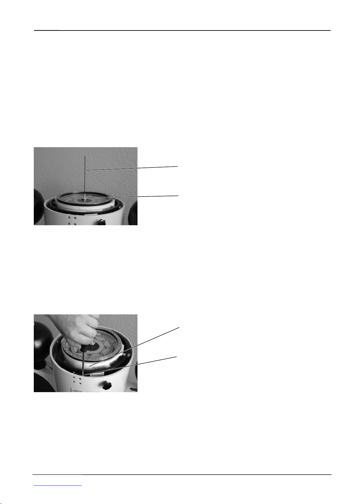
Shadow Pin ...........................................................................................................................................B3
Removing the Compass out of the Binnacle.........................................................................................B3
Spare Compass.....................................................................................................................................B3
Maintenance of Compass and Compass Binnacle...............................................................................B3
Compass Adjustment
General..................................................................................................................................................C1
A-Correction ..........................................................................................................................................C1
B+C-Correction......................................................................................................................................C1
D(μ)-Correction......................................................................................................................................C2
D(cylinder)-Correction...........................................................................................................................C3
Heeling-Correction ................................................................................................................................C3
E-Correction ..........................................................................................................................................C5
Mainenance, Errors, Repair
Maintenance
Lubrication of Compass Suspensions ........................................................................................D1
Compass Routine Service ..........................................................................................................D1
Replacing Bulbs..........................................................................................................................D1
Cleaning of Reflector Optics.......................................................................................................D2
Errors, Diagnosis and Help
Visible Compass Errors ..............................................................................................................D3
Indication Errors..........................................................................................................................D3
Replacement of compass ...........................................................................................................D3
Workshop Repair of Compass..............................................................................................................D5
Installation
Procedure, Outline ................................................................................................................................E1
Range of Delivery..................................................................................................................................E1
Location of Binnacle, Magnetic Requirements......................................................................................E2
Location of Binnacle, Constructional Requirements.............................................................................E3
Optical Arrangement (Reflection Tube), Requirements for Installation ................................................ E4
Compass Foundation, Cut-outs and Drillings .......................................................................................E5
Installation of the Optical Arrangement (Reflection Tube)....................................................................E6
Installation of Compass Binnacle..........................................................................................................E8
Illumination ..........................................................................................................................................E10
Illumination Dimmer.............................................................................................................................E10
Replacing of the Bulbs ........................................................................................................................E10
Wiring ..................................................................................................................................................E11
Setting into Operation, Function Tests & Preparing of Adjustment ....................................................E12
Alterations / Errors reserved
Cassens & Plath GmbH, Am Lunedeich 131, 27572 Bremerhaven, Germany, Tel. +49 471 483 999 0, Fax +49 471 483 999 10
www.cassens-plath.de, [email protected]

Introduction, General REFLECTA/5
Page A3 Mounting & Operations Manual
Compass Binnacle, Outline
As to be seen from ahead as to be seen from astern
6
4
7
3
8 9
10
2
3
4
5
1
1
1 Hood (turn and remove) 6 Compass
2 Binnacle Base 7 Fixing flange of reflection tube
3 Compass bridge 8 Knurled knob for reflection mirror
4 Reflection tube 9 Reflection mirror
5 Mirror head with aperture 10 Foundation
Alterations / Errors reserved
Cassens & Plath GmbH, Am Lunedeich 131, 27572 Bremerhaven, Germany, Tel. +49 471 483 999 0, Fax +49 471 483 999 10
www.cassens-plath.de, [email protected]

Introduction, General REFLECTA/5
Page A4 Mounting & Operations Manual
General
Magnetic compasses have to be installed in a sufficient distance to any magnetic iron as well as to the different
navigational instruments. Therefore the preferred location is the compass bridge. To read the heading at the
helmsman´s position inside the wheelhouse one makes use of a reflection arrangement. This is an optical
arrangement consisting of magnification lenses and mirrors. According to SOLAS regulations the remote
reading has to be independent of electrical means.
The magnetic compass is found within the compass column. It is easy to remove and to replace with another
one. Spare magnetic compasses are obligatory according to SOLAS.
In spite of the distance to any magnetic source a deflecting influence -the deviation- cannot be totally excluded.
For correction of these residual errors the compass has to be equipped with separate correctors.
Installation of magnetic compasses and the requirements for their location are laid down in basic national and
international regulations. These are IMO A.382(X) and SOLAS consolidated Edition, Chapter V, regulation 12.
The technical and design requirements for magnetic compasses are laid down in ISO 25862:2009(E) as well as
in the relevant national documents. REFLECTA/5 fullfills all these regulations for costal navigation.
Technical Data
Compass Binnacle
Card height..........................................................................................................................210 - 600 mm
Total height......................................................................................................................... 510 - 900 mm
Maximum width measured over D-cylinders ................................................................................800 mm
Weight of binnacle and compass complete................................................................................ net 30 kg
Material of binnacle column................................................................seawater resistant light alloy, RFG
Built-in correctors................................................................................................................................... no
Reflector/steering compass type 21
Diameter of directional system..................................................................................................... 160 mm
Orientations of card printing from below for reflection reading .................................................N below N
Card division........................................................................................................................................1/1°
Magnet................................................................................................................................................Ring
Magnetic moment...............................................................................................................typically 2 Am2
Damping factor ....................................................................................................................... typically 3.3
Working temperature range............................................................................................. -30°C .... +65°C
Swirl error accroding to ISO 25862:2009(E) ....................................................................................< 1.6°
Friction-/north error according ISO 25862:2009(E)..........................................................................< 0.5°
Half period .......................................................................................................................................13 sec
Tilt freedom of card within compass bowl .......................................................................................+/- 10°
Rolling/pitching tolerance of compass in gimbal suspension........................................................+/- 180°
Weight................................................................................................................................................10 kg
Reflection arrangement
Type CUTUBE .....................................................................................length 1000 mm to be cut by yard
Type FIXTUBE................................................................................... ready adjusted in length at delivery
Diameter of tube........................................................................................................................... 125 mm
Material...............................................................................................................................................PVC
Turning range of mirror head..............................................................................................................360°
Swivel range of reflection mirror, black and white..............................................................................360°
Alterations / Errors reserved
Cassens & Plath GmbH, Am Lunedeich 131, 27572 Bremerhaven, Germany, Tel. +49 471 483 999 0, Fax +49 471 483 999 10
www.cassens-plath.de, [email protected]

Introduction, General REFLECTA/5
Page A5 Mounting & Operations Manual
Range of delivery
Compass Column
• Reflector compass column individually adjusted in height with mounting pieces, hood without window,
magnetic steering compass Type/21.
Built-in Correctors
no
Separate Correctors (Extras)
• B+C-corrector magazine (#18100), consisting of 3 magazines with 4 bar magnets 100 mm long x 10 mm ∅
(at delivery inserted in magnet magazine behind B+C-corrector).
• D(μ)-Correctors (#12200)with centre pivot, glued to top cover glass of compass. Set of weak iron induction
metal plates.
• D(cylinder)-Correctors (#12050) with mounting brackes. Mounted to port and starboard of the binnacle
column.
Reflection tube
• Reflection tube with mirror head and mounting flange, rubber gasket.
Accessories as option
Instruction are included separately as required.
Approvals
Type/21 compass is type approved by German BSH and European MED for coastal use.
MED - European Community .................................. BSH/4612/4011402/09
Certificates of Lloyds Register of Shipping LRS, German Lloyd GL, Amercian Bureau of Shipping ABS can be
supplied on request.
Type/21 compass fullfills the international specifications: ISO 25862:2009(E), IMO A.382(X), SOLAS (1992,
Chapter V, Regulation 12) as well as IMO High Speed Craft-Code MSC 36 (63) May 1994.
The required approval has to be stated with order because there are technical differences.
Alterations / Errors reserved
Cassens & Plath GmbH, Am Lunedeich 131, 27572 Bremerhaven, Germany, Tel. +49 471 483 999 0, Fax +49 471 483 999 10
www.cassens-plath.de, [email protected]

Operation REFLECTA/5
Page B1 Mounting & Operations Manual
Operation
How to Read the Heading
It should be possible to read the heading clearly from a distance of 1 m from the mirror head in the wheelhouse
at the helmsman´s position. The image has to be centric to the field of view. The figures are upright and on both
sides of the lubber mark an area of minimum 15° should be visible.
Use an illumination dimmer (as option) for brightness control to be operated from the helmsman´s position.
In case of long optical ways (long by-passes) the picture may be much smaller then the reflection mirror.
030 040 050 060 030 040 050 060
Short optical way: large image Long optical way: small image
Adjustment of Mirror Head
Reflection tube
Mirror head
Take the rotary knobs here by hand
to turn and swivel reflection mirror
Reflection mirror.
White mirror for daylight use,
black mirror for night use.
Maintenance: Clean reflection mirrors with a weak, not scratching cloth. The axles of the rotary knob have to be
oiled from time to time. Clean the lens inside the binnacle column from time to time. For this remove the
compass from the binnacle column and the lens will be seen.
Alterations / Errors reserved
Cassens & Plath GmbH, Am Lunedeich 131, 27572 Bremerhaven, Germany, Tel. +49 471 483 999 0, Fax +49 471 483 999 10
www.cassens-plath.de, [email protected]

Operation REFLECTA/5
Page B2 Mounting & Operations Manual
Direct Reading of Heading on the Compass Bridge
Remove the hood. Read the heading at the ahead lubber mark of the compass.
The second, aft orientated lubber mark is for officer´s inspection. Add here 180° correction to get the ship´s
heading.
Removing/Attaching of Binnacle Hood
Take hood with both hands
Loosen two knurled knobs
Turn hood and lift
When closing the binnacle again
carefully secure the hood by fixing
the knurled knob!
Maintenance: Guiding surface of hood should be lubricated from time to time.
Taking Bearings (optional only)
REFLECTA/4 includes as standard a steering type compass without a graduated scale on top for taking
bearings. A bearing compass type is an option. So a vane type azimuth device with shadow pin is not included
in the standard range of delivery but can be supplied as extra.
To apply (if a bearing compas type is used) remove the binnacle hood to set up the azimuth device onto the
centre pivot of the upper compass cover glass. Open object (wire) sight vane and ocular (slit) sight vane. Use
the circular peep in the ocular (slit) sight vane for a rough pick-up of the bearing mark. For accurate bearing use
the slit of the ocular sight-vane.
Compass bearing (azimuth) of land marks up tp 30° of elevation:
Read the compass card as illustrated below.
Relative bearing of land marks up to 30° of elevation:
Read the graduated verge ring of the compass at the index of the ocular sight-vane. The scale ring is marked
all-round. If semi-circuar bearings are required subtract 360° from the all-round value for objects port side of the
vessel. The starboard bearings remain unchanged.
Sun or star azimuth by azimuth mirror:
The black mirror at the object sight-vane can be hinged up and down according to the star height. The darkness
is suitable to allow sun observations (before make sure that sun will not dazzle!). Read the bearing as required
at the divided verge ring of the compass or at the compass card. Make sure that the compass is horizontal
balanced. It is not recommended to take bearings of astronomical objects heigher that 45° because each
accidental inclination of the compass will distort the measurement.
Slit sight (ocular side)
Wire sight (object side)
Foldable black mirror
for sun azimuth
Reading of relative bearings
Reading of compass bearings
Certre pivot for guiding the azimuth device
Alterations / Errors reserved
Cassens & Plath GmbH, Am Lunedeich 131, 27572 Bremerhaven, Germany, Tel. +49 471 483 999 0, Fax +49 471 483 999 10
www.cassens-plath.de, [email protected]

Operation REFLECTA/5
Page B3 Mounting & Operations Manual
While taking bearings make sure that the compass is horizontally levelled!
Maintenance: The turning joints of both sight-vanes and of the black mirror as well as the centre hole should be
oiled from time to time. Clean and tighten the wire of the wire sight-vane. The azimuth device should be easy to
rotate on the centre pivot and should not clatter when turned.
Shadow Pin (optional only)
Only in combination with bearing compasses. As standard REFLECTA/4 includes a steering compass without a
graduated scale on top. A shadow pin is stowed in the wooden box of the azimuth device (as extra only). This
can be inserted into the drilling of the centre pivot. Now the sun´s shade can easily be recognized on the white
compass card. The shadow direction makes it possible to calculate the compass deviation and to adjust the
compass.
Shadow pin
Centre pivot
Removing the Compass out of the Binnacle
Remove the hood and the compass and its suspensions fore and aft will be visible. These are covered by safety
plates to fix the compass in its position. Loosen the screws of the safety plates and remove the compass. If a
detector is fitted watch the cables! Unfit the detector cables either by removing the connector or by unscrewing
the wires in a junction box. Dont remove the detector itself from the compass, because this destroys the
alignment!
When reinstalling the compass make sure that the detector cable does not obscure the reflection channel.
Furthermore the cable should not be in direct neighbourhood to the illumination bulbs because the heat may
destroy the insulation. In addition the cables should not limit the compass movement.
The compass is marked by an ahead label. The zero marking of the divided verge ring shows to aft.
Ahead marking of compass
Unscrew safety plate to remove the
compass
Spare Compass
Store spare compass upside down to reduce friction of the pivot.
Maintenance of Compass and Compass Binnacle
Refer to chapter “Maintenance, Errors, Repair“
Alterations / Errors reserved
Cassens & Plath GmbH, Am Lunedeich 131, 27572 Bremerhaven, Germany, Tel. +49 471 483 999 0, Fax +49 471 483 999 10
www.cassens-plath.de, [email protected]

Compass Adjustment REFLECTA/5
Page C1 Mounting & Operations Manual
Adjustment of the Compass
General
Compass adjustment is necessary to neutralize the deflecting magnetic fields caused by the ship´s steel hull or
superstructure.
The first adjustment has to be made on maiden voyage. Later, it should be repeated periodically according to
the requirements of the maritime authority. Furthermore it should be carried out additionally on particular
circumstances like reconstruction works, lightning stroke, grounding .....
It is necessary to call a qualified compass adjuster for adjustment works.
Before adjustment the vessel must be ready for sea: cargo derricks, hatchway covers, davits.....are to be
positioned as on voyage.
Further details will be found in “Handbook of Compass Adjustment“, Pub. 226 of U.S. Department of Defense,
Defense Mapping Agency.
A-Correction
This is to correct the alignment error of the compass binnacle: Compass ahead and ships ahead have to be
corresponding. For correction loosen the binnacle fixing bolts in the base. Oblong holes in the base allow to turn
the binnacle column by +/-5° around its vertical axis.
Separate B+C-Correction magazines (#18100, Extra)
B+C are for adjustment of the permanent longitudinal and cross ship field.
3 pcs of varnished wooden magazines with 6 pcs ISO magnets (200 mm long x 10 mm ∅). The magnets are
stored within one of the magazines.
This corrector arrangement adjusts about 35° of deviation if compass and magazines are mounted as directed.
Unscrew the side covers to make out the drillings to insert the magnets.
For B-adjustment install one each magazine at port and starboard of the compass as to be seen from the
following drawing 1. The magnets have to be exact parallel to ship´s longitude.
The remaining C-magazine can be fixed ahead or aft of the compass. The magnets have to be exact to ship´s
cross direction.
The distance between the nearest points of compass and corrector magazine should be 200 mm.The magazine
plane may be orientated horizontal, vertical or every angle between (drawing 2). It is essential to have the B-
magnets parallel to ship´s longitudinal direction and the C-magnets parallel to ship´s cross direction. Protect the
magazines against water!
After Installation adjustment of compass by a professional compass adjuster is necessary.
Drawing 1) Arrangement as to be seen from above
Voraus
Ahead
B-magnets, longitudinal
B-Magnete, längsschiffs
B-magnets,
exact longitudina
l
B-Magnete,
Compass Column
Kompass Säule abt. 20 cm
ca. 20 cm
exakt längsschiffs C-magnets, cross orientated.
Magazine also alternatively to
install ahead of compass
C-Magnete, querschiffs.
Tasche kann auch voraus vom
Kompass montiert sein.
Alterations / Errors reserved
Cassens & Plath GmbH, Am Lunedeich 131, 27572 Bremerhaven, Germany, Tel. +49 471 483 999 0, Fax +49 471 483 999 10
www.cassens-plath.de, [email protected]

Compass Adjustment REFLECTA/5
Page C2 Mounting & Operations Manual
Drawing 2) Alternative Positions of Magazines, Side View
Abbildung 2) Alternative Anordnung der Taschen, von der Seite gesehen
B, C magazines, side view.
Here vertically mounted.
B, C Taschen, seitlich
gesehen. Hier vertikal montiert B, C Taschen, seitlich
gesehen. Hier horizontal
montiert.
Magazines abt. 20 cm Distance to binnacle
Magazine ca. 20 cm Abstand zur Säule
B, C magazines,
side view. Here
horizontally mounted.
D(
μ
)-Corrector (#12200, Extra)
The D(μ)-corrector is the usual D-corrector for coastal navigation, so it is the standard corrector for
REFLECTA/5 reflector reading device and ist compass. For coastal navigation means, that this type of corrector
cannot be used for a wide range of magnetic latitudes. If the compass shall be used for high seas navigation the
D(cylinder)-corrector #12050 has to be installed.
The D-corrector is to adjust the induced weak magnetic field caused by the magnetic iron hull or superstructure
of the vessel. It can neutralize 6° of deviation (heading error). The correction by μ-metal induction sheets works
on needle induction and will vary with magnetic latitude. Therefore it is intended only for limited voyage in
coastal navigation, on fishing vessels or tugs.
The D-corrector arrangement consists of a centre pivot and 2x4 weak iron μ-metal stripes of different length.
The centre pivot is fixed (or has to be glued) at the centre of the upper (standard) or lower cover glass of the
compass. Slits in cross ship direction. Use stripes of suitable length and fasten these with the screw at the
centre pivot.
Insert
μ
-stripes of suitable length into the
slits and fix it by the screw.
μ-Streifen geeigneter Länge seitlich in die
Schlitze einführen und mit Schraube
festklemmen.
μ
-stripes / μ-Streifen
Fixing screw / Feststellschraube
Alterations / Errors reserved
Cassens & Plath GmbH, Am Lunedeich 131, 27572 Bremerhaven, Germany, Tel. +49 471 483 999 0, Fax +49 471 483 999 10
www.cassens-plath.de, [email protected]

Compass Adjustment REFLECTA/5
Page C3 Mounting & Operations Manual
D-(cylinder) Correction (#12050, Extra)
D-(cylinder) Correctors compared to D-(μ) Correctors allow stable correction world wide. At delivery the D-
brackets are mounted at the binnacle column and the D-cylinders are packed separately. For attaching there
are bolts and washers. There are index marks at the cylinders and scales at the D-bracket to note the position
in the deviation diary.
For D-correction the cylinders has to be approached or drawn away from the binnacle column.
D-Bracket
Binnacle Column
D-Cylinder
Bolt to fix the sphere
Adjustment
Heeling Correction (#12800, Extra)
First Install reflection tube as describted in this handbook.
Reflection tube
Reflexions Roh
r
Binnacle column
Standsäule
Voraus
Ahead
Heeling Corrector.
On compass axis!
K-Kompensierung
Auf Kompassachse!
Alterations / Errors reserved
Cassens & Plath GmbH, Am Lunedeich 131, 27572 Bremerhaven, Germany, Tel. +49 471 483 999 0, Fax +49 471 483 999 10
www.cassens-plath.de, [email protected]

Compass Adjustment REFLECTA/5
Page C4 Mounting & Operations Manual
Heeling corrector tube
Strictly aft
!
K-Magnet Hülse
Strikt Achteraus! Fixing flange
Befestigungsflansch
Reflection Tube
Reflexionsrohr
Mirror Head
Spiegelkopf
Chain for adjusting the magne
t
Kette zum Justieren des
K-Magneten
Take out Magnet
Magnethülse oben herausnehmen
or
Unscrew to take out the magnet below
Schraube Lösen zur Entnahme des
Magneten von unten
Slit to arrest the chain
Schlitz zur Arretierung der Kette
Numbered adjusting chain
Nummerierte Justierkette
Magnet tube with chain, remove
d
Magnethülse an Kette, entnommen
Heeling magnet.Turn to turn the field direction
K-Magnet. Drehen für Feldumkeh
r
Unscrew cover to turn the magne
t
Deckel abschrauben zum Drehen des Magnet
Alterations / Errors reserved
Cassens & Plath GmbH, Am Lunedeich 131, 27572 Bremerhaven, Germany, Tel. +49 471 483 999 0, Fax +49 471 483 999 10
www.cassens-plath.de, [email protected]

Compass Adjustment REFLECTA/5
Page C5 Mounting & Operations Manual
E-Correction
Is used for correction of the ship´s asymmetrical weak iron field.
This compass binnacle does not include this corrector because according to regulations it should be installed in
the ship´s centre line where the influence does not occur. If it is necessary to move the compass binnacle to
port or starboard then the iron free zone has to be moved correspondingly to reduce the deflection.
Alterations / Errors reserved
Cassens & Plath GmbH, Am Lunedeich 131, 27572 Bremerhaven, Germany, Tel. +49 471 483 999 0, Fax +49 471 483 999 10
www.cassens-plath.de, [email protected]

Maintenance, Errors, Repair REFLECTA/5
Page D1 Mounting & Operations Manual
Content
Maintenance...............................................................................................................................D1
Lubrication of Compass Suspensions..............................................................................D1
Compass Routine Service................................................................................................D1
Replacing Bulbs ...............................................................................................................D1
Cleaning of Reflection Optics...........................................................................................D2
Errors, Diagnosis and Help.........................................................................................................D3
Visible Compass Errors....................................................................................................D3
Indication Errors...............................................................................................................D3
Friction Error and Swirl Error Test....................................................................................D4
Replacement of compass.................................................................................................D4
Workshop Repair of Compass ...................................................................................................D5
Maintenance
Ensure propper operation of the magnetic compass whenever possible to guarantee safe navigation!
Lubrication of Compass Suspensions
This has to be done from time to time to grant free movement of compass bowl.
Compass Routine Service
A faulty compass function is difficult to detect by onboard means. Therefore a routine service is recommended.
Often certain service intervals are laid down in the national regulations. According to German BSH regulations
an inspection of the compass is necessary every year year for passenger and every five years for freight
vessels. The correct function will be certified by the BSH authorized compass work shop by the official BSH test
certificate. If the compass service was carried out by a foreign and not BSH authorized work shop (because the
vessel has not called a German port) the certificate issued can be sent to the BSH for acceptance.
A preliminary functional test with oboard means is described below in chapter “Friction Error and Swirl Error
Test“. This should be carried out from time to time. A positive result is not be understood as guarantee for a
reliable operation but in case of a negative result the compass should be immediately replaced with the spare
compass, sent to a qualified compass workshop or order replacement compass, see below.
Replacing Bulbs
Use glow lamps of type E14, 40VA (60 VA) with 14 mm screw socket only.
The illumination arrangement is to be found in the upper part of the binnacle column and will be accessible after
removing of hood and compass.
Illumination.
Remove compass for free
access.
Alterations / Errors reserved
Cassens & Plath GmbH, Am Lunedeich 131, 27572 Bremerhaven, Germany, Tel. +49 471 483 999 0, Fax +49 471 483 999 10
www.cassens-plath.de, [email protected]

Maintenance, Errors, Repair REFLECTA/5
Page D2 Mounting & Operations Manual
Cleaning of Reflection Optics
Use only a soft and non scatching cloth.
Lens Position:
Alterations / Errors reserved
Cassens & Plath GmbH, Am Lunedeich 131, 27572 Bremerhaven, Germany, Tel. +49 471 483 999 0, Fax +49 471 483 999 10
www.cassens-plath.de, [email protected]

Maintenance, Errors, Repair REFLECTA/5
Page D3 Mounting & Operations Manual
Errors, Diagnosis and Help
Visible Compass Errors
• Bubbles in the fluid, broken cover glass, buckled compass bowl, tilted compass bowl, loose in suspension,
dirty or cloudy fluid or similar.
⇒Take compass out of operation immediately (replace with spare compass or order replacement compass,
see below) and hand over to a qualified service workshop as soon as possible.
• Directional system tilted
Possible reason:
A slight sinking of the north mark on north latitudes and of the south mark on south latitudes is normal and
result from the variation of the vertical earth field on different magnetic latitudes.
Remove the compass from its position within the binnacle and take it to a magnetically undisturbed location
for example ashore. If the tilt remains the reason is the earth´s vertical field and not the ship´s vertical field.
This tilt does not exceed about 5°.
⇒No further action is necessary.
Possible other reason:
The ship´s vertical field or the heeling corrector is unadjusted.
Remove the compass from its position within the binnacle and take it to a magnetically undisturbed location
for example ashore. If the tilt disappears the reason is the ship´s vertical field and not the earth´s vertical
field.
⇒Carry out heeling adjustment.
Possible other reason:
A strong card tilt often in combination with bubbles in the fluid, with the upper or lower points not near to the
north or south mark may be caused by a leaking float. Sometimes the upper or lower points are moving with
time.
⇒Take compass out of operation immediately (replace with spare compass or order replacement compass,
see below) and hand over to a qualified servce workshop as soon as possible.
Indication Errors
• Static Indication Errors:
Indication errors can be discovered by comparison of magnetic compass and gyro compass indication.
Magnetic and gyro compass indicate different types of heading: Magnetic and true. So when compare both
apply variation and deviation correction.
These indication errors may be caused by a faulty compass (non visible errors) or by a faulty adjustment.
⇒If friction and swirl error test (below) are not successful, the reason might be a defective compass. Take
compass out of operation immediately (replace with spare compass or order replacement compass, see
below) and hand over to a qualified service workshop as soon as possible.
If friction and swirl error tests are successful the compass seems to be in order. Carry out compass
adjustment.
• Dynamic Indication Errors
Indication oszillates correlated with rolling of the vessel. If the oszillation is strongest on north or south
headings and smallest on east or west headings this is most probably caused by unadjusted ship´s vertical
field.
⇒Arrange heeling adjustment.
• Unstable indication, seemingly arbitrary oszillation of the indcation
Possible reason:
Strong vibration of the compass which results in a rise and spin of the directional system.
⇒Fix compass binnacle more strongly. Install lashings for the compass binnacle (supply Cassens & Plath).
Possible other reason:
Pivot/jewel suspension of the directional system is defective.
⇒If friction and swirl error tests (below) are not successful take compass out of operation immediately
Alterations / Errors reserved
Cassens & Plath GmbH, Am Lunedeich 131, 27572 Bremerhaven, Germany, Tel. +49 471 483 999 0, Fax +49 471 483 999 10
www.cassens-plath.de, [email protected]

Maintenance, Errors, Repair REFLECTA/5
Page D4 Mounting & Operations Manual
(replace with spare compass or order replacement compass, see below) and hand over to a qualified servce
workshop as soon as possible.
Possible other reason:
The orientating earth´s horizontal field at the place of the magnetic compass is too weak. This may be
caused by the ships position, by wrong adjustment or an insufficient compass safe distance to magnetic iron
or instruments. Furthermore the position of the adjusting magnets perhaps has been changed accidentally or
the ship´s own magnetic field has been altered by grounding, lightning stroke or welding works.
⇒Make sure that the correction magnets are at the position as mentioned in the deviation diary.
Repeat compass adjustement and check the safe distances of the compass.
Friction Error and Swirl Error Test
The following simple examinations for onboard use will only give a provisional result for reliable compass
operation. A definite proof of faultless function can only be granted by a qualified service workshop.
1. Place the compass on a horizontal baseplate as free as possible of deflecting magnetic fields and free of
vibrations. This may be a place on board of the ship, e.g. the chart desk. Better is a place on shore where
only the earth´s magetic field is effective. If the compass test should be carried out on board the ship should
not be moving. Mark the place of the compass to make sure the same magnetic and other conditions in any
direction for the following tests. Note the heading indication.
2. Let the directional system stabilize on a certain direction. Knock slightly with your fingertip onto the cover
glass. Now use a piece of light magnetic material (e.g. a key) to deflect the compass card by 2° only. Wait
until the card has stabilized in this new orientation.
3. Now quickly pull away the deflecting magnet. Watch how the card returns to the undeflected direction. A
tolerance of less 0.5° is acceptable after stabilizing.
4. Deflect the compass card as mentioned above to the opposite direction by 2° and repeat the settling
process. Again, the compass card must return to the original direction within a tolerance of 0.5°.
5. Repeat these tests each 45° of compass orientation.
6. If the compass card returns to the respective original orientation within the tolerance of +/-0.5° on each of
these 8 directions, pivot and jewel suspension of the card assembly are, so far, in order.
7. Take the compass with both hands and hold it horizontally in front of you. Turn yourself (ideally one turn of
360° within 4´) and watch the movement of the directional system. The card should show to north the whole
turn and its movement should be steady without jerking. If the directional system is abruptly dragged with the
movement of the compass it is defective.
If friction and swirl error test are not successful take compass out of operation immediately (replace with spare
compass or order replacement compass, see below) and hand over to a qualified service workshop as soon as
possible.
Even if these tests are successful routine compass checks still have to be carried out.
Replacement compass
In case certificates have to been renewed or a replacement compass is necessary Cassens & Plath offers an
exchange service of refurbished compasses. Contact: [email protected]. State type of compass, serial
number, flag or required certificate, any detector fixed to the compass, date of last certificate & date of last
compass adjustement. C&P will send a refurbished compass to the next available stopp of the vessel and
invoice. The ship may return to C&P the old compass and we will buy it back. The ship will have a pay back
after inspection of the returned compass.
Alterations / Errors reserved
Cassens & Plath GmbH, Am Lunedeich 131, 27572 Bremerhaven, Germany, Tel. +49 471 483 999 0, Fax +49 471 483 999 10
www.cassens-plath.de, [email protected]

Maintenance, Errors, Repair REFLECTA/5
Page D5 Mounting & Operations Manual
Workshop Repair of Compass
Compass repair should be carried out by qualified compass workshops only to grant safe navigation!
Repair or exchange by a refurbished compass?
In case certificates have to been renewed or a replacement compass is necessary Cassens & Plath offers an
exchange service of refurbished compasses. Contact: [email protected]. State type of compass, serial
number, flag or required certificate, any detector fixed to the compass, date of last certificate & date of last
compass adjustement. C&P will send a refurbished compass to the next available stopp of the vessel and
invoice. The ship may return to C&P the old compass and we will buy it back. The ship will have a pay back
after inspection of the returned compass.
Spare Parts
(In case of order please quote part description and also type of compass -here steering- (optional reflector-)
compass Type 21)
Compass Fluid
If less then 5 cm3fluid has to be completed use pure Ethanol or distilled water. If it is more, only use original
Cassens & Plath compass fluid #39012.
Don´t use any different fluid because this may destroy the compass and impair the function!
Alterations / Errors reserved
Cassens & Plath GmbH, Am Lunedeich 131, 27572 Bremerhaven, Germany, Tel. +49 471 483 999 0, Fax +49 471 483 999 10
www.cassens-plath.de, [email protected]

Maintenance, Errors, Repair REFLECTA/5
Page D6 Mounting & Operations Manual
5-Years-Spare-Parts-Outfit
A box containing the most essential spare parts is availale as an extra (Order No. 10651).
Included are:
1. One cover glass/bottom glass
2. Two rubber gaskets
3. Two filling screw gaskets
4. Two pivots for the directional system assembly
5. Two jewels
6. Three each bulbs for illumination
7. One centre pivot for azimuth device (only bearing compass)
8. One reflection mirror
Required Tools
Special tools are not required.
• Slot screw driver, 3 mm, to unscrew the pivot from the float,
• Box wrench, 5.5 mm, or pointed pliers for counter nut of the pivot
• Slot screw driver, 7 mm, for the cover rings of the compass
• Slot screw driver, 12 mm, for the filling screw of the compass
• Pipe wrench for removal of external gimbal trunnions
• Screw spanner, 17 mm, for the internal gimbal trunnions
Replacement of Directional System (Card Assembly) or Pivot and Jewel
1. Place the compass on a horizontal plane and solid surface.
2. Remove the divided verge ring by unscrewing the relevant screws (only bearing/reflector compass). The
“180“ mark is in ahead direction.
3. Remove the upper cover ring by unscrewing the relevant screws. Mark the orientation before.
4. Remove rubber gasket and cover glass. Mark the orientation of the cover glass before. Take the cover glass
with the centre pivot or use a small screw driver and lift up the glass at its edge.
5. Remove the directional system by hand and replace by a new one if necessary.
6. Remove pivot. Loosen the pivot counter nut from below of the float by use of the box wrench 5.5 mm or
pointed pliers. Now the pivot can be unscrewed from above with the screw driver of 3 mm. Replace with a
new pivot (recommended each time the compass is opened or latest at routine service).
7. Replace the jewel: Unscrew the jewel retainer by hand or with pliers. Now take the jewel and replace by a
new one.
8. Close the compass with the cover glass. Watch its orientation. The cover glass should be centric to the
compass bowl. Check this visually. Insert the rubber gasket and fasten the upper cover ring. Tighten the
screws with as equal as possible force around the whole circle.
9. Fit the divided verge ring (if any). Place the azimuth device on the compass for adjustment. Adjust the
divided verge ring to match the lubber marks.Turn the azimuth device to all four major directions and adjust
the divided ring to be centric to the centre pivot.
10.Fill up the compass fluid. Refer to paragraph: “Filling the compass“.
Replacement of Upper Cover Glass
1. Place the compass on a horizontal, plane and solid surface.
2. Only bearing/reflector compass: Remove the divided verge ring by unscrewing the relevant screws. The
“180“ mark is in ahead direction.
3. Remove the upper cover ring by unscrewing the relevant screws. Mark the orientation before.
4. Remove rubber gasket. Take the cover glass at the centre pivot or use a small screw driver and lift up the
glass at its edge.
5. Replace the old cover glass with a new one.
6. The cover glass should be centric to the compass bowl. Check this visually. Insert the rubber gasket and
fasten the upper cover ring. Tighten the screws with as equal as possible force around the whole circle.
7. Only bearing/reflector compass. Fit the divided verge ring. Place the azimuth device on the compass for
adjustment. Adjust the divided verge ring to match the lubber marks.Turn the azimuth device to all four major
directions and adjust the divided ring to be centric to the centre pivot.
8. Complete the compass fluid. Refer to paragraph: “Filling the compass“.
Alterations / Errors reserved
Cassens & Plath GmbH, Am Lunedeich 131, 27572 Bremerhaven, Germany, Tel. +49 471 483 999 0, Fax +49 471 483 999 10
www.cassens-plath.de, [email protected]

Maintenance, Errors, Repair REFLECTA/5
Page D7 Mounting & Operations Manual
Replacement of the Bottom Glass
1. Place the compass upside down on a horizontal, plane and solid surface. Caution: do not lay down the
compass on its protruding centre pivot (if any)! Use a plate (e.g. cardboard) of approximate 10 mm thickness
as suporting surface with hole for the centre pivot.
2. First unscrew weight ring and then lower cover ring. Mark the orientation of both.
3. Remove the rubber gasket.
4. Take the defective bottom glass with a small screw driver and lift up the glass at its edge. Insert the new
glass which must be centric to the bowl.
5. Complete the compass and fill in fluid. Refer to paragraph: “Filling the compass“.
Replacement of Gaskets.
1. For replacement of upper gasket proceed as described in the paragraph “Replacement of cover glass“.
2. For replacement of lower gasket proceed as described in the paragraph “Replacement of bottom glass“.
Filling the Compass
1. Place the compass so that the filling screw is upside. Unscrew the filling screw with screw driver of 12 mm
and complete fluid. In case larger quantities are needed use only original compass fluid #39012. Smaller
quantities up to 5 cm3can be completed with Ethanol or distilled water. Medical syrings are suitable to
complete the fluid.
2. Close the compass with the filling screw. Use a new gasket.
3. To ensure the tightness of the compass cool it to -30°C and keep it approximately 8 hours at this
temperature. If there is no bubble in the fluid after this time the compass should be in order.
Replacement or Dressing of Gimbal Ring
1. Use a pipe wrench for removal of the external gimbal trunnions. For that cover the trunnion with emery paper
to keep its surface smooth and to prevent slipping of the pipe wrench.
2. Remove the internal gimbal trunnions by use of a screw spanner of 17 mm.
3. Now dress the gimbal ring with a light rubber hammer after having it separated from the compass bowl. The
slack must be less 0.2 mm.
Alterations / Errors reserved
Cassens & Plath GmbH, Am Lunedeich 131, 27572 Bremerhaven, Germany, Tel. +49 471 483 999 0, Fax +49 471 483 999 10
www.cassens-plath.de, [email protected]
Table of contents
Popular Industrial Equipment manuals by other brands

jost
jost Modul E-Drive Installation and operating instructions

Eaton
Eaton Moeller EU5E-SWD-8DX installation instructions

Interroll
Interroll Diverter SH 1500 Installation and operating instructions

Buhler
Buhler SZLH-400b operating instructions

eao
eao 57 Series Assembly instructions

Siemens
Siemens SIRIUS ACT 3SU19 operating instructions