molgen PurePrep 96 User manual

Operation Manual
V1.4
PurePrep 96
Nucleic Acid Purification System

Revision history
Version number
Description of revision
Date revision
Revised by
V1.0
Initial release version
21-06-2019
Xu Tao
V1.1
Increase of the temperature rise time
index
23-08-2019
Xu Tao
V1.2
Addition of the U-disk accessories
15-05-2020
Xu Tao
V1.3
Namen instrument en adres
aangepast
7-1-2021
John R.
V1.4
Aanpassing tekst en layout
7-1-2021
Marlieke D.

Foreword
Thank you for purchasing our PurePrep 96 Nucleic Acid Purification System. This manual describes the
function and operation of the instrument. In order to use the instrument properly, please read this
manual carefully beforehand. Keep it as reference book to solve possible difficulties you may
encounter.
Check before first use
Please check the instrument and accessories according to the packing list when you first open the
packing case. If anything is wrong or missing, please contact the supplier or service point.
MolGen BV
Kazemat 23, Veenendaal, The Netherlands
Website: www.molgen.com
Outside EU, please contact:

Safety Warnings and Guidelines
Important information for safe use
Users should have a clear understanding of how to use this instrument before operation, please read
this manual carefully prior to operation.
Any improper operation may cause injuries or electric shocks. Please read
the manual carefully and operate safely according to the guidelines.
Security
The operation and maintenance of the instrument should comply with the basic guidelines and
warnings below. Incorrect operation or maintenance will have effect on life expectancy, performance,
and safety features of the instrument.
The instrument is generally an indoor instrument which conforms to the
class GB 4793.1 standard.
Please read this manual carefully before operation. The device must be
used by experienced personnel with certified training.
The operator should not repair the instrument in case any injury or out of
warranty. If service required, please contact MolGen or your local supplier
for repair.
Before powering on, please make sure the voltage of the power supply is
consistent with the required voltage. And make sure the rated load of the
power outlet is not less than required by the instrument.
If the power cord is damaged, replace it with the same type and
specification power cord. Do not cover anything on the instruments when
using. Insert and pull the power line with hand gently and make sure the
plug completely inserts to the jack.
The temperature of the heating block is high, please do not touch it during
the operation in case any injury.

The instrument should be kept in an area with minimal dust, away from wet
areas and direct sunlight. In additional the installation location should have
sufficient ventilation, but away from electromagnetic interference and heat
sources. The vents on this instrument are designed for ventilation. Do not
cover them, as they may overheat. When many instruments are used at the
same time, the distance between each instrument should be more than
100cm.
Power off when not in use. If the instrument will not be used for a long
period of time, cover it with a cloth or plastic to protect it from dust.
Disconnect the power cord from the jack at once in the following cases, and
contact your local supplier or MolGen:
⚫Liquid enters into the Instrument;
⚫Instrument was rained or watered;
⚫Abnormal operation: such as abnormal sound or smell;
⚫Instrument was dropped or the outer shell is damaged;
⚫The function has obviously changed.
Maintenance
The instrument should be cleaned regularly using a soft cloth with a small amount of alcohol. If there
are any stains on the surface of the instrument, wipe it with soft cloth with cleansing cream.
Transportation and storage requirements
Ambient temperature: 10℃~ 35℃
Relative humidity: ≤70%
Atmosphere pressure range: 500 ~ 1060hpa
Locate it in a well-ventilated room, away from corrosive gas.

Table of contents
Chapter 1. Introduction...................................................................................................... 6
1.1. Application ........................................................................................................... 7
1.2. Contraindication................................................................................................... 7
1.3. Service Life ........................................................................................................... 7
Chapter 2. Specifications.................................................................................................... 8
2.1. Working Conditions.............................................................................................. 8
2.2. Basic Parameters .................................................................................................. 8
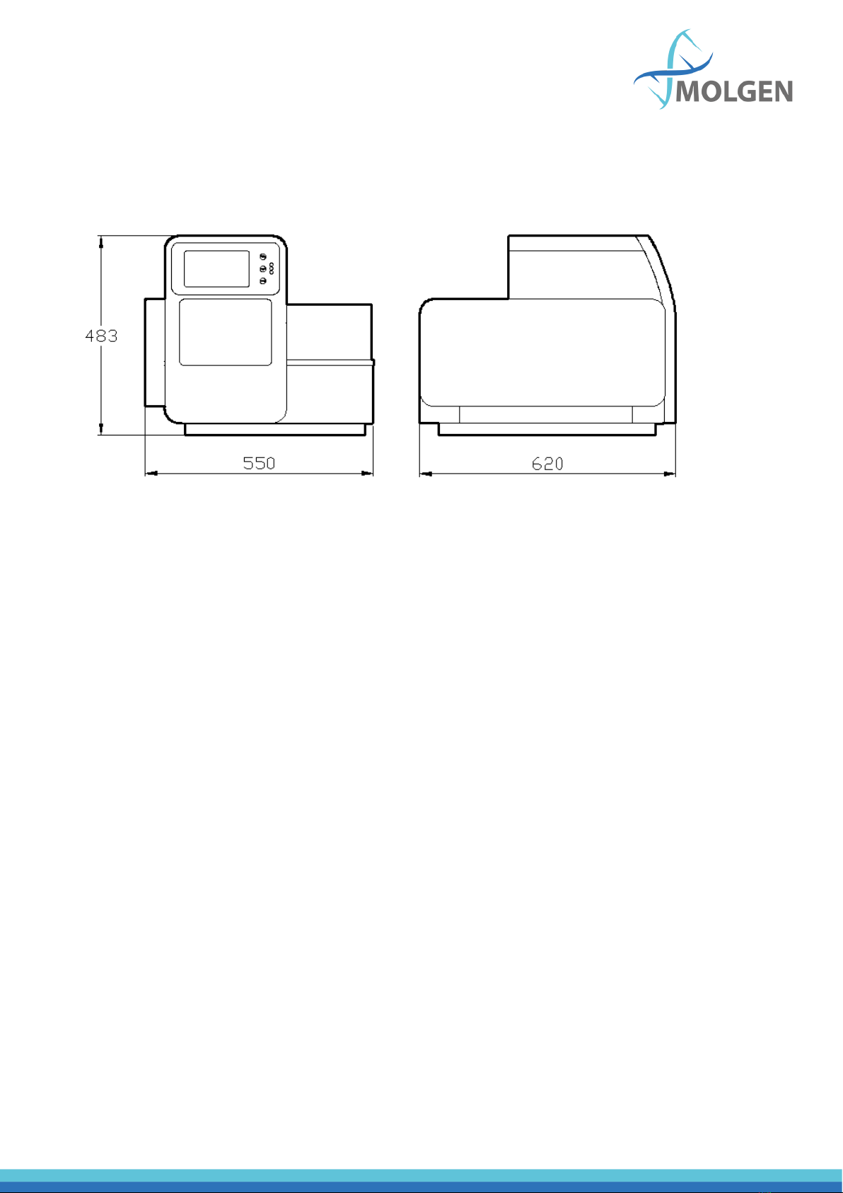
2.3. Overall Dimensions ........................................................................................... 9
Chapter 3. Basic Operating Instructions ........................................................................... 10
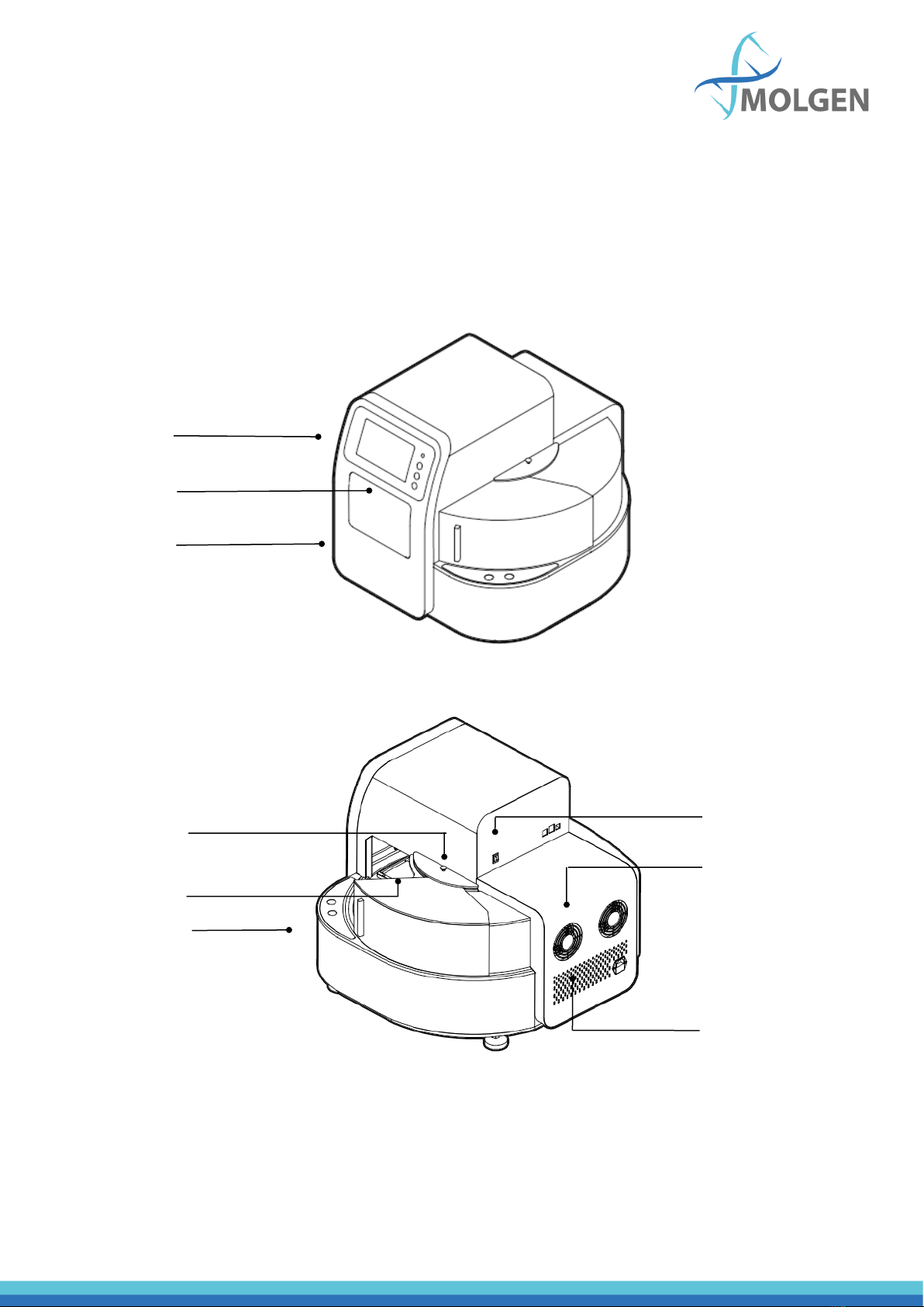
3.1. Structures........................................................................................................ 10
3.1.1. Front..................................................................................................... 10
3.1.2. Back...................................................................................................... 10
3.1.3. Cabin Door ........................................................................................... 11
3.1.4. Transparent Cover ................................................................................ 11
3.1.5. Touch Screen ........................................................................................ 12
Chapter 4. Operations ...................................................................................................... 13
4.1. Power Connection .............................................................................................. 13
4.2. Kits Installation................................................................................................... 13
4.3. Detailed Operations............................................................................................ 14
4.3.1. Start-up Interface..................................................................................... 14
4.3.2. Run Program Interface............................................................................. 14
4.3.3. Run Interface ........................................................................................... 16
4.3.4. View......................................................................................................... 19
4.3.5. Manage Program ..................................................................................... 21
4.3.6. System Settings........................................................................................ 25
4.3.6. Lighting.................................................................................................... 29
4.3.7. Auxiliary function..................................................................................... 29
4.3.8. UV Sterilization ........................................................................................ 30
Chapter 5. Trouble Shooting............................................................................................. 31
5.1. Troubleshooting ................................................................................................. 31
5.2. Software error alarm list..................................................................................... 32
Chapter 6 Accessory......................................................................................................... 33
Chapter 7. Abbreviations and Tags.................................................................................... 34
7.1. Abbreviations ..................................................................................................... 34
7.2. Tags .................................................................................................................... 35

Chapter 1. Introduction
The PurePrep 96 nucleic acid purification instrument is a newly launched automatic extraction and
purification system for DNA/RNA, proteins and cells. It uses specialized magnetic separation
technology and can be used for many different matrices. Some examples of matrices used are blood,
cultured cells or bacteria, tissues, cell-free body fluids and plant samples. The PurePrep 96 can be used
in high-throughput flows, as users can extract DNA/RNA from 1~96 samples simultaneously with
various kits. It has an open and multiple functions design to provide more methods for reagent
optimization. The operation is very simple, to be used without a computer, and controlled using a 7
inch touch screen.
1.1. Application
This instrument is suitable for the extraction and purification of nucleic acids in animal and plant
tissues, blood and body fluids and other samples (mainly used in human body samples). Some notable
applications are for research purposes in the seed, plant breeding, animal sciences and agrotechnology
industries. Additionally, the PurePrep 96 is used for research and testing for COVID-19.
1.2. Contraindication
No contraindication.
1.3. Service Life
Service life of the instrument is five years. For the production date, please see the label on back of the
instrument.

Chapter 2. Specifications
2.1. Working Conditions
Environmental Temperature: 10C~35C
Relative Humidity: ≤70%
Input Voltage: AC 100~240V,50Hz/60Hz
2.2. Basic Parameters
Model
Parameters
PurePrep 96
Principle
Magnetic Particle Method, Magnet type
Sample Volume
50μL—1000μL
Throughput
96
Stability
CV≤5%
Extraction time
10 ~ 60min/run
Temperature control
module
Ambient temperature ~ 120℃for lysis and elution
Heating time
Heating time(Ambient temperature ~120℃)≤7 minutes
Temp. Accuracy
±1℃
Vibrate and mix
10 different speeds and options
Operation
7 inch color touch screen, mouse can be connected
Programs
8 groups of programs can be preset, and can store 100 groups
of programs
Program
management
Includes create, edit, delete protocol modes
Extension interface
With USB port and Ethernet port
Network
Extended Ethernet remote control, WiFi function,4G
Power Supply
AC100-240V, 50Hz/60Hz, 450VA

2.3. Overall Dimensions
The below figure (fig 1) shows the dimensions of the PurePrep 96. The units are in mm.
Fig 1

Chapter 3. Basic Operating Instructions
This chapter mainly introduces structures, basic operation keys, displays, as well as preparations
before starting up. Please read this chapter carefully before using this instrument.
3.1. Structures
3.1.1. Front
Fig 1
3.1.2. Back
Fig 3
Power Socket
Fuse
Power Switch
USB Port
Fan
Screw to remove
transparent cover
Screw to remove
panel
Display
Shortcut keys
and indicator
lights
Cabin door

3.1.3. Cabin Door
The cabin door of the PurePrep 96 can be opened which is convenient for cleaning and maintenance.
Fig 4
3.1.4. Transparent Cover
The transparent cover is on the right side of the instrument, which assists in placing or taking out
plates. The cover can be removed which makes it convenient matching with automatic liquid transfer
workstation.
Fig 5
Heating plate
Cabin door
Magnetic rod
Magnetic rod’s tip
Transparent cover
Screw for quick removal

3.1.5. Touch Screen
Fig 6
Display screen: Touch screen, mouse also can be connected for operation.
TAB: Select shortcut program.
RUN: Start the shortcut program and run the instrument.
STOP: Stop the operation.
Display screen
TAB
RUN
STOP
Indicator light

Chapter 4. Operations
4.1. Power Connection
The power necessary for the PurePrep 96 is AC 100 ~ 240V.
4.2. Kits Installation
Open the cabin door, press the position button (figure 7) to turn the rotary table and place all the
plates on their proper position of the rotary table. The PurePrep 96 is suitable for 96-well plates.
Fig 7
Position button

4.3. Detailed Operations
4.3.1. Start-up Interface
Make sure the front door and the plastic side door are closed beforehand, and turn on the machine
using the power button on the back of the machine. On the display screen, the start-up interface will
show up (see figure 8).
Fig 8
After some time loading, it will enter into “Run Prog.” interface.

4.3.2. Run Program Interface
This interface including two modes: “shortcut mode” and “list mode”, as shown in below Fig 9 and Fig
10.
Fig 9
Fig 10
In the “List mode” interface, if a program is selected/activated in “Shortcut” column, the icon of the
program can be displayed on shortcut interface. A maximum of eight programs can be activated as
shortcut at the same time.
“SN”, “Name”, “Modify time” and “Lock” are non-editable options.

4.3.3. Run Interface
In “List mode” or “Shortcut” mode, select the required program and click “Run” to enter the run
interface.
When starting a run, the instrument will first detect whether there is are plates on the rotary table. If
no plate is found, the program will prompt to confirm whether the following steps can be continued,
as shown in the figures 11 and 12 below.
Fig 11
Fig 12

The instrument will install magnetic rod sleeves automatically. If rod sleeves are already installed on
the current magnetic rod sleeve rack, "Sleeve loaded, continue?” will pop up (see figure 13). If no
magnetic rod sleeve is detected after installing the magnetic rod sleeve, "No sleeve, continue?" will
appear (see figure 14).
Fig 13
Fig 14

After the magnetic rod sleeve is successfully installed, the instrument automatically performs the
following steps (see figure 15).
Fig 15
In the running interface, users can stop, pause, continue or run the program again. Plate number 1
(dark blue in figure 15) is the working plate, the red corner mark on it means the plate is running or
already finished running, while the blue corner mark means the plate is ready to run. One corner mark
means one run and two means two runs.
After the completion of the operation, the No. 8 plate position will be automatically pushed to the
transparent cover on the right side.

4.3.4. View
Select the required program (in the list mode or shortcut mode) and click the “View” button to enter
the view interface (see figure 16). Users can view all parameter settings of the program.
Fig 16
Users can click the button in the upper right corner to switch to the graphic display. The highlighted
row indicates the plate position which corresponds to the selected step (see figure 17). If you press
“Steps Run”, the program will run starting from currently selected step.
Fig 17

Click the button to open the magnetic parameter absorption interface which shows the magnetic
parameters of the selected step (see figure 18). Clicking the button “Option” will display the settings of
the program (see figure 19).
Fig 18
Fig 19
Table of contents