Cast Tec POLARIS INSET ECO User manual

Polaris Inset Eco Manual Ref No: I17. V1.
POLARIS INSET ECO
Multi-fuel stove
Ref No: I17.
Version 01 (06.03.2023)
Installation and Operating Instructions
The Polaris Inset Eco stove must be installed by a suitably qualified engineer.
Instructions must be given to the user when installation is completed, and the installer must instruct user of the
correct use of the appliance and control operation.
The Polaris Inset Eco and the optional Polaris Integra cast iron fireplace are manufactured by
Cast Tec Ltd. East Side, Tyne Dock, South Shields NE33 5SP
Website: www.casttec.co.uk - Tel. 0191 4974280
Polaris Inset
Polaris Integra

Polaris Inset Eco Manual Ref No: I17. V1.
2 Cast Tec Ltd
TABLE OF CONTENTS
THE CLEAN AIR ACT 1993 AND SMOKE CONTROL AREAS ............................................................................. 3
INSTALLATION ESSENTIALS .......................................................................................................................... 4
PRE-INSTALLATION CHECKS ......................................................................................................................... 4
TECHNICAL INFORMATION .......................................................................................................................... 5
INSTALLATION ............................................................................................................................................. 8
FITTING INSTRUCTIONS ............................................................................................................................. 10
FIT THE INDIVIDUAL COMPONENTS IN THE FOLLOWING ORDER ................................................................ 12
DOWN DRAUGHTS .................................................................................................................................... 13
VENTILATION AND COMBUSTION AIR REQUIREMENTS ............................................................................. 13
PERMANENT AIR VENT EXTRACTOR .......................................................................................................... 14
EXTRACTOR FAN ....................................................................................................................................... 14
COMMISSIONING & HANDOVER ............................................................................................................... 15
LOCATION ................................................................................................................................................. 15
CLEARANCE TO COMBUSTIBLES ................................................................................................................. 15
FLOOR PROTECTION .................................................................................................................................. 17
CHOICE OF FUEL ........................................................................................................................................ 17
USE ........................................................................................................................................................... 18
ASH REMOVAL .......................................................................................................................................... 21
DETACHABLE HANDLE ............................................................................................................................... 22
MAINTENANCE ......................................................................................................................................... 23
SPARE PARTS ............................................................................................................................................. 25
OPERATIONAL PROBLEMS & TROUBLESHOOTING ..................................................................................... 28

Polaris Inset Eco Manual Ref No: I17. V1.
3 Cast Tec Ltd
THE CLEAN AIR ACT 1993 AND SMOKE CONTROL AREAS
The CastTec Polaris Inset Eco multi-fuel stove has been recommended for exemption from
UK smoke control areas when burning wood. Note that authorised fuels can also be used in
a Smoke Control Area, details of authorised fuels can be found
at https://smokecontrol.defra.gov.uk/fuels.php.
Under the Clean Air Act local authorities may declare the whole or part of the district of the
authority to be a smoke control area. It is an offence to emit smoke from a chimney of a
building, from a furnace or from a fixed boiler if located in a designated smoke control area.
It is also an offence to acquire an “unauthorised fuel” for use within a smoke control area
unless it is used in an “exempt appliance (“exempted” from the controls which generally
apply in the smoke control area).
In England appliances are exempted by publication on a list by the Secretary of State in
accordance with changes made to sections 20 and 21 of the Clean Air Act 1993 by section
15 of the Deregulation Act 2015. In Scotland appliances are exempted by publication on a
list by Scottish Ministers under section 50 of the Regulatory Reform (Scotland) Act 2014.
In Wales and Northern Ireland these are authorised by regulations made by Welsh Ministers
and by the Department of the Environment respectively.
Further information on the requirements of the Clean Air Act can be found here:
https://www.gov.uk/smoke-control-area-rules
Your local authority is responsible for implementing the Clean Air Act 1993 including
designation and supervision of smoke control areas and you can contact them for details of
Clean Air Act requirements.
The CastTec Polaris Inset Eco has been recommended as suitable for use in smoke control
areas when burning wood logs and authorised fuels. The CastTec Polaris Inset Eco is fitted
with a permanent stop to prevent closure of the secondary air control beyond 50% open.

Polaris Inset Eco Manual Ref No: I17. V1.
4 Cast Tec Ltd
INSTALLATION ESSENTIALS
The installation of a fireplace or stove must be in accordance with local codes and
regulations in each country and other national and European standards that apply.
Your Polaris Inset Eco stove must be installed by a Competent Person registered with a
Government Approved Competent Person’s Scheme.
In the UK, HETAS is a qualified body that can assist with general advice, regulation,
installation, type of fuel usage and can provide a list of registered Competent Persons:
Website is www.hetas.co.uk.
PRE-INSTALLATION CHECKS
Installation of a fireplace must be according to local codes and regulations in each country.
All local regulations, including those which refer to national and European standards, must
be observed when installing the product.
Both an installation manual with technical data and a manual on general use and
maintenance are enclosed with the product. The installation can only be used after it has
been inspected by a qualified inspector. A name plate of heat-resistant material is affixed to
the product. This contains information about identification and documentation for the
product.

Polaris Inset Eco Manual Ref No: I17. V1.
5 Cast Tec Ltd
TECHNICAL INFORMATION
Polaris Inset Eco Diagram
Polaris Integra Eco Diagram
The CastTec Polaris Integra is a cast-iron insert that integrates with the Polaris Inset Eco
to create an efficient traditional fireplace. (See Figs. 2 and 3)
Figure 1
Figure 2

Polaris Inset Eco Manual Ref No: I17. V1.
6 Cast Tec Ltd
Polaris Integra Assembly
Figure 3
2 x M6 countersunk bolts screw into Outer Fascia.
2 x M6 wing nuts and washers accessed behind the canopy.
Canopy
M6 Bolts
M6 Wing Nuts

Polaris Inset Eco Manual Ref No: I17. V1.
7 Cast Tec Ltd
TECHNICAL DATA ACCORDING TO NEN EN 13229:2001 and NEN EN13229 - A2: 2004
WOOD
ANTHRACITE
STOVE
Polaris Inset Eco
FUEL
Multi-Fuel
NOMINAL HEAT OUTPUT
4.6 kW
4.8 kW
ENERGY EFFICIENCY
79.2 %
76.8 %
MINIMUM FLUE SIZE
125 MM
DIST. COMBUSTIBLES
Side: 350 MM
Above: 600 MM
LOG LENGTH
>22 cm
2” - 3”
FLUE OUTLET
Top
FLUE PIPE DIMENSION
125 MM
RECOMMENDED CHIMNEY DRAUGHT
12 Pa
OPERATIONAL MODE
Intermittent*
MATERIAL
Cast-iron
FINISH
High Temp. Resistance Paint
WEIGHT
75 kg
*Intermittent combustion in this context means normal use of the STOVE,
i.e., fuel is added as soon as the fuel has burnt down. This is not intending for overnight burning.

Polaris Inset Eco Manual Ref No: I17. V1.
8 Cast Tec Ltd
INSTALLATION
Installing this stove
The stove and chimney installations MUST comply with all current National and Local
Building Regulations; your approved dealer or your local building control officer can
advise regarding this. Ultimately, it is you and your installer who is responsible that the
installation complies.
Pre-installation
After removing the stove from the packaging, open the fire door and remove the loose
packing. Prior to installation all the internal components of the stove are removed to gain
access to fixings and to make it lighter for installation.
A. Remove the refractory fire bricks, these
bricks are loose and just need to be lifted
clear of the grate support plate before they
can be removed.
B. To remove the loose baffle, lift the front
edge until it hits the top and then slide it
forward. Then drop the rear edge and the
baffle will slide down. To remove the fixed
baffle, loosen the two screws and slide it
forwards, it will then drop down.
C. Next, remove the riddle knob from the
riddle bar positioned at the front left of the
stove. Remove the inner riddling grate and
bar before pushing up the outer grate from
underneath. This will allow access to four
M6 fixings which will attach the stove to
the outer casing. Remove the 4 fixings,
allowing the insert stove to be removed
from the external casing.
Figure
4

Polaris Inset Eco Manual Ref No: I17. V1.
9 Cast Tec Ltd
Chimney
THIS PRODUCT IS SUITABLE FOR CHIMNEY INSTALLATION ONLY.
The stove is a radiant room heater with
convection chamber and must be connected to
a chimney of the proper size and type. The
chimney must have a cross sectional area of
at least 124cm2 or a diameter of at least
125mm. Never connect to a smaller size
chimney. Do not connect to a chimney serving
another appliance. Minimum chimney height
4.5 meters from floor on which stove is
installed.
It is recommended that a flue liner of diameter
125mm be used to line the chimney, the liner
should be approved for use with solid fuel.
(See Fig. 4.)
It is permitted to connect using a closure plate
and a connection piece from the stove to the
closure plate (See Fig. 5.), provided that the
chimney is of sound construction with no leaks
or cracks, a clay flue liner has been used that
can withstand up to 1000oC, the clay liner has
a diameter no greater than 200mm.
ALL FLUE INSTALLATIONS ARE THE RESPONSIBILITY OF THE CUSTOMER.
The stove must be connected to a chimney with a minimum continuous draught of 12
Pascal’s (.05” WG). Poor draught conditions will result in poor performance.
Figure 5

Polaris Inset Eco Manual Ref No: I17. V1.
10 Cast Tec Ltd
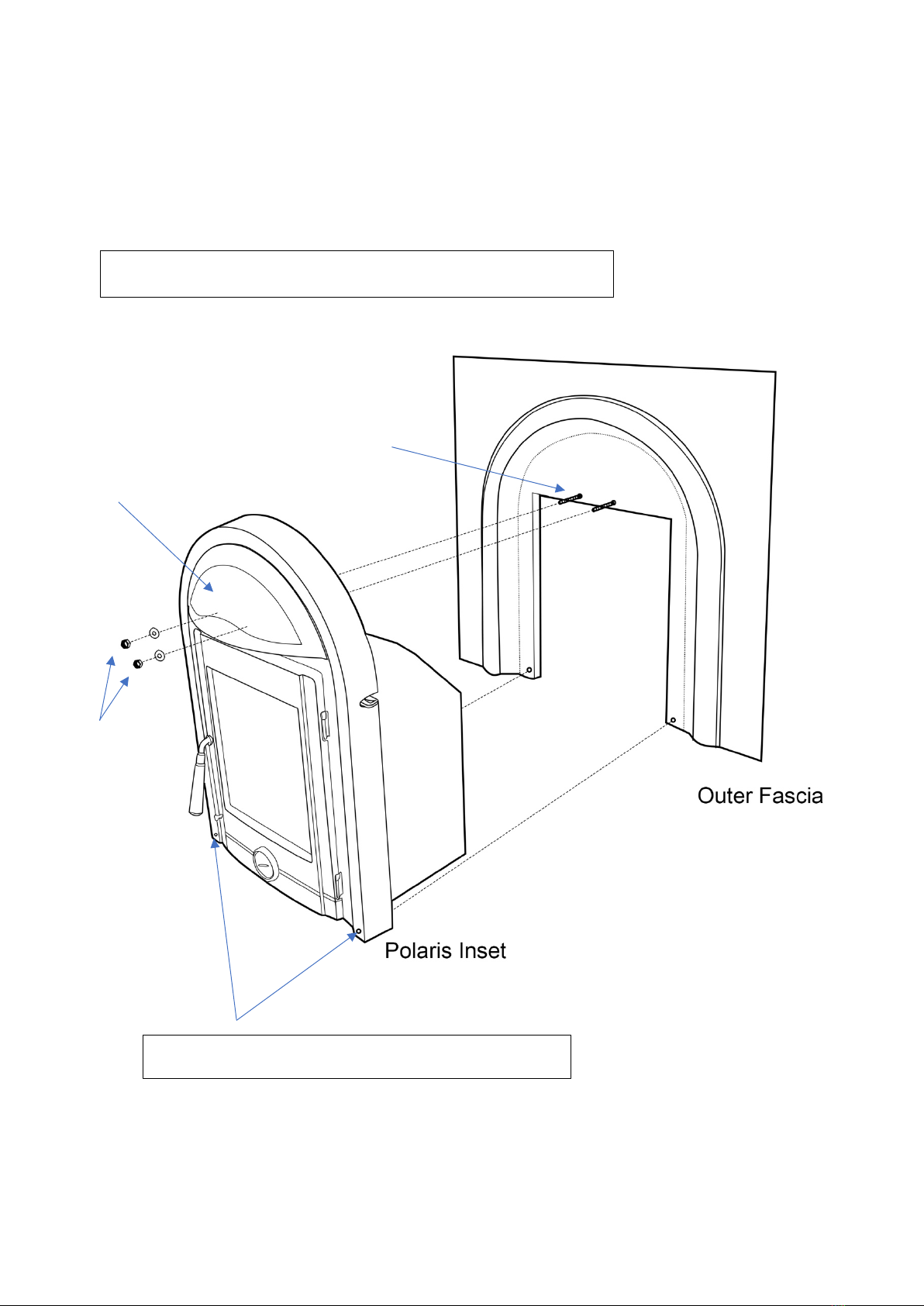
FITTING INSTRUCTIONS (POLARIS INSET ONLY)
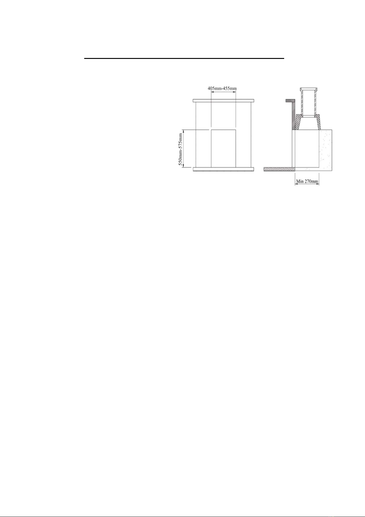
Step 1. Prepare the fireplace area
with fireback or milner brick removal.
Ensure the opening is suitable for
fitting of the insert stove opening
required, i.e., remove fire surround
trim if fitted. (See Fig. 6.)
Step 2. Ensure the floor area is level
with the hearth, this area needs to be
level as the insert fire is screw fixed
to the floor.
Step 3. Lay the external casing into
the opening and position so that the front edge protrudes 20mm past the front edge of
the opening.
Step 4. Mark the drill location and drill the holes using a 4.5mm drill bit. Fix the casing
to the floor using the self-tapping screws provided.
Step 5. Lift the stove into the external casing. Remove all internal parts as per pre-
assembly instructions prior to lifting it. The stove can be lifted into the casing
approximately 125mm first and then it can be pushed into the final position while taking
care to lift the front edge to preserve the hearth.
Step 6. Drop the flexi flue liner with adaptor end attached into the fire opening ready to
connect to the appliance.
Step 7. Lay the sealing gasket on to the flue spigot, and then fit the flue spigot to the
end of the flexi flue liner using the 2 grub screws provided.
Step 8. Then using the M6 screws secure the stove to the convection chamber. Push
the insert stove against the fireplace before fully tightening these bolts.
Step 9. Reach up through the stove and pull the stove collar down and secure the flue
collar to the stove with the two flue collar’s bolts. (See fig. 7.)
Step 10. Complete the installation of the flexi liner at the top of the chimney in
accordance with the manufacturer’s instructions.
Figure 6

Polaris Inset Eco Manual Ref No: I17. V1.
11 Cast Tec Ltd
FITTING INSTRUCTIONS (POLARIS INTEGRA)
Step 1. Prepare the Fireplace area with the fireback or milner back removed. Ensure
the opening is a suitable size to accommodate the Polaris Inset. (See Fig. 6.)
Step 2. Ensure the rear hearth floor area is level with the front hearth, this area will
need to be level.
Step 3. Build the ‘Outer Facia’ cast iron back panel against the chimney wall, bridged
off the wall as required with non- combustible packing to match the chosen surround
rebate, the edges of the cast iron outer fascia can be drilled and countersunk to allow
secure wall fixing, Ensure the surround hides the fixing holes! Cement flaunch the outer
edges of the cast iron back panel to ensure an airtight fit against the chimney wall. Seal
the inner edges of the “Outer Fascia” in preparation of the stove insertion.
Step 4. Drop the flexi flue liner with adapter end attached into the fire opening ready to
connect to the appliance.
Step 5. Strip out the inside components of the Polaris Inset to gain access to remove
the spigot, then attach this to the flexi liner/adapter end.
Step 6. Push the ‘Polaris’ inset fascia into the back panel and secure with 2 x wing nuts
behind the canopy and 2 x counter sunk bolts at the base. (See fig. 3.)
Step 7. Gain access from inside the Polaris stove then reach up through the stove and
pull the stove collar down and secure the flue collar to the stove with the 2-x flue collar
fixing bolts. (See fig. 7.) (Flue Liner not shown for illustration purposes)
Step 8. Replace The inside components and complete the installation of the flexi liner at
the top of the chimney in accordance with the manufacturer’s instructions.
Figure 7

Polaris Inset Eco Manual Ref No: I17. V1.
12 Cast Tec Ltd
FIT THE INDIVIDUAL COMPONENTS IN THE FOLLOWING ORDER
1. Grate Support
Tilt the grate support up on one
side and pass it carefully
through the door opening.
2. Riddle Grate
The grate simply lays into the
grate support, but care needs
to be taken that the riddling
bar will rest in the middle of
the riddle connecting plate.
With the riddle grate in
position, and the riddle bar
located through the hole on
the front left of the stove, then
connect the cylindrical handle
to the end of the riddle bar
and tighten with the Allen key
provided.
3. Back Bricks
Lay the back bricks in as
shown.
4. Baffle
Lay the baffle on the back
brick, then hold it meanwhile
lay the left and right side
brick.
5. Side Bricks
Lay the side and back bricks in as shown.
6. Fuel Retainer
Lay the fuel retainer into the slots provided ensuring that they slope from front to back so
that no embers can fall out through the fuel retainer.
Figure 8

Polaris Inset Eco Manual Ref No: I17. V1.
13 Cast Tec Ltd
DOWN DRAUGHTS
However well designed constructed and positioned,
the satisfactory performance of the flue can be
adversely affected by down draught caused by
nearby hills, adjacent tall buildings or trees. These
can deflect wind to blow directly down the flue or
create a zone of low pressure over the terminal. A
suitable anti-down draught terminal or cowl will
usually effectively combat direct down blow but no
cowl is likely to prevent down draught due to a low
pressure zone. (See Fig.9.)
VENTILATION AND COMBUSTION AIR
REQUIREMENTS
This appliance is rated less than 5kW, therefore
there is no mandatory requirements for additional
air unless a flue draught stabiliser is fitted then the
air requirement is 15 cm². However, we suggest that
it is advantageous to provide an air supply into the
room.
When calculating combustion air requirements for
this appliance use the following equation: 550 mm².
per each kW of rated output above 5 kW should be
provided, where a flue draught stabiliser is used the
total free area shall be increased by 300 mm² for
each kW of rated output. If there is another
appliance using air fitted in the same or adjacent
room, it will be necessary to provide an additional
air supply.
All materials used in the manufacture of air vents
should be such that the vent is dimensionally stable,
corrosion resistant, and no provision for closure. The effective free area of any vent should
be ascertained before installation. The effect of any grills should be allowed for when
determining the effective free area of any vent.
Air vents direct to the outside of the building should be located so that any air current
produced will not pass through normally occupied areas of the room.
Figure 9

Polaris Inset Eco Manual Ref No: I17. V1.
14 Cast Tec Ltd
An air vent outside the building should not be located less than the dimensions specified
within the Building Regulations and B.S. 8303: Part 1 from any part of any flue terminal.
These air vents must also be satisfactorily fire proofed as per Building Regulations and B.S.
8303: Part 1.
Air vents in internal walls should not communicate with bedrooms, bedsits, toilets,
bathrooms or rooms containing a shower.
Air vents traversing cavity walls should include a continuous duct across the cavity. The
duct should be installed in such a manner as not to impair the weather resistance of the
cavity.
Joints between air vents and outside walls should be sealed to prevent the ingress of
moisture. Existing air vents should be of the correct size and unobstructed for the appliance
in use. If there is an extraction fan fitted in adjacent rooms where this appliance is fitted,
additional air vents may be required to alleviate the possibility of spillage of products of
combustion from the appliance/flue while the fan is in operation. Refer to B.S. 8303 Part 1.
Where such an installation exists, a test for spillage should be made with the fan or fans
and other appliances using air in operation at full rate, (i.e. extraction fans, tumble dryers)
with all external doors and windows closed.
If spillage occurs following the above operation, an additional air vent of sufficient size to
prevent this occurrence should be installed.
PERMANENT AIR VENT EXTRACTOR
The stove requires an adequate air supply in order for it to operate safely and efficiently.
The installer may have fitted a permanent air supply vent into the room in which the stove is
installed to provide combustion and/or ventilation air. This air vent should not under any
circumstances be shut off or sealed.
EXTRACTOR FAN
There must not be an extractor fan fitted in the same room as the stove as this can cause
the stove to emit smoke and fumes into the room.

Polaris Inset Eco Manual Ref No: I17. V1.
15 Cast Tec Ltd
COMMISSIONING & HANDOVER
On completion of the installation allow a suitable period of time for any fire cement and
mortar to dry out, when a small fire may be lit and checked to ensure the smoke and fumes
are taken from the stove up the chimney and emitted safely to the atmosphere. Do not run
at full output for at least 24 hours.
On completion of the installation and commissioning ensure that the operating instructions
for the stove are left with the customer. Ensure to advise the customer on the correct use of
the appliance with the fuels likely to be used on the stove and warn them to use only the
recommended fuels for the stove.
Advise the user what to do should smoke or fumes be emitted from the stove. The customer
should be warned to use a fire guard to BS 6539 in the presence of children, aged and/or
infirm persons.
LOCATION
There are several conditions to be considered in selecting a location for your stove.
a. This product is designed to be installed into a fireplace.
b. Allowances for proper clearances to combustibles.
CLEARANCE TO COMBUSTIBLES
This appliance must be installed in a recess, the recess should not contain any combustible
materials. Wooden battens and plaster board should not be used within the clearance to
combustibles. The minimum clearance to combustibles required is 600mm to the top,
350mm to the sides, 550mm directly to the front and 350mm to any combustible flooring.
If the mantelpiece protrudes further than 100mm from the fireplace, then it will be necessary
to have further clearance to the top of the stove. The distance the mantle protrudes past the
100mm should be added to the clearance.
For example, if the mantle protrudes 200mm, the clearance to the mantle should be
650mm. (See Fig. 10.)

Polaris Inset Eco Manual Ref No: I17. V1.
16 Cast Tec Ltd
If there is a studded wall surrounding the fireplace as in Fig. 10, ensure the clearances in
this Fig. 11 are adhered to.
Figure 10
Figure 11

Polaris Inset Eco Manual Ref No: I17. V1.
17 Cast Tec Ltd
FLOOR PROTECTION
It is recommended that this appliance is installed on a solid, level, concrete base, a
noncombustible hearth conforming to current Building Regulations must extend to the front
of the appliance.
CHOICE OF FUEL
1. Recommended fuel: Wood.
a. Use hard wood logs.
Although you can fire this product with almost all kinds of wood, you should not fire with wet
wood, or unseasoned wood. Wood ought to be stored under a roof for at least 1 year, and
preferably 2 years, with free access to wind. Wood should be chopped as soon as possible
after felling if it is to dry quickly. The wood can be used once the moisture content is less
than 20%. During the EN test, all stoves are tested with wood with a moisture content of (16
± 4) %.
• Hardwood has a higher calorific value as the same volume (oak, ash, maple, birch,
elm, beech, etc.).
• Pieces of wood with a diameter greater than 10 cm should always be chopped. The
pieces of wood should be short enough to be able to lie flat over the layer of embers,
with air at both ends. The maximum length of fuel in the stove is no more than 30cm.
2. Recommended fuel: Solid Fuel.
a. Smokeless fuels, including coalite nuts, phurnacite, ancit and extracite. (See
www.hetas.co.uk for latest information)
Not Recommended as Fuel:
• “Green wood”. Green or damp wood reduces stove efficiency and soils the glass, the
internal walls and the flue (soot, tar, etc.).
• “Used timbers”. Burning treated wood (railway sleepers, telegraph poles, offcuts of
plywood or chip board, pallets, etc.) quickly clogs the flue ways (soot, tar, etc.),
pollutes the environment (pollution and smell, etc.) and cause the fire to burn too
quickly and overheat.
• “Green wood” and “recovered wood” can eventually cause a chimney fire.
• Prohibited fuel: plastic bags and any form of bituminous coal or petroleum-based
coke. This may harm the product and pollute the atmosphere.

Polaris Inset Eco Manual Ref No: I17. V1.
18 Cast Tec Ltd
USE
• Painted products: the fireplace may emit an irritating gas when used for the first
time, and it may smell a little. The gas is not toxic, but the room should be thoroughly
ventilated. Let the fire burn with a high draught until all traces of the gas have
disappeared and no smoke or smells can be detected.
• Polished Cast Iron products: Condensation may form on the surface of the
fireplace the first few times it is used. This must be wiped off to prevent permanent
stains forming when the surface heats up.
Air Control: Figure 12
The amount of heat emitted by the stove is regulated using two air controls. The primary air
supply, where air passes up through the riddling grate, is controlled using the lower air
control and the secondary air (air wash system), which is supplied to the combustion over
the glass, is controlled using the upper air control.
1. USE WITH WOOD
Lighting - Figure 12
1. Slide the top air control to open. Open the lower control.
2. Lay firelighters or rolled up newspapers on the grate with a reasonable quantity, if
necessary, of dry kindling wood. Place 2 or 3 small logs on top.
3. Light the newspaper or firelighters using a long taper and close the door.
4. When the fire is burning fiercely, add further logs of a diameter up to 10 cm.
5. When the stove body is very hot, close the lower control.
6. The burning rate can now be lowered by moving the top air control to smaller air
inlet.
Re-fueling - Figure 12
1. Slide the top air control to open. Open the lower control.
2. Open the glass door and add logs. (To load fuel, the door should be opened slowly,
avoiding a sudden rush of intake air, so that smoke does not escape into the room.)
3. Leave the lower control open for a few minutes to allow the initial volatiles in the
wood to burn.
4. Close the lower control.

Polaris Inset Eco Manual Ref No: I17. V1.
19 Cast Tec Ltd
Very Important: Wood is a material that contains a great deal of gas (approximately 75 %).
The gases are released when the wood is lit and heated up. For this reason, it is important
that the gases are ignited quickly after stoking. If the wood just lies smoldering, especially
after re-stoking, a lot of smoke is created, which, in the worst case, may cause an explosive
ignition of the gasses, resulting in damage to the stove.
In order to ignite the gases that are released from the wood, and to keep clear, lasting
flames during the combustion process, it is important to always let in the required quantity
of oxygen (air supply). The setting of the air supply, the method of ignition and the lighting
intervals depend on the draught in the chimney, the wind and weather, the amount of heat
required the fuel, etc. This means that it may take some time before you get to know the
correct functioning of the stove under any given circumstances.
2. USE WITH SOLID FUEL
Lighting - Figure 12
1. Slide the top air control to open. Open the lower control.
2. Lay firelighters or rolled up newspapers on the grate with a reasonable quantity, if
necessary, of dry kindling wood. Place a small quantity of solid fuel on top.
3. Light the newspaper or firelighters using a long taper and close the door.
4. When the fire is burning fiercely, add further fuel.
5. When the stove body is hot, close the top air control.
6. The burning rate can now be adjusted by the lower control.
Re-fueling - Figure 12
1. Open the lower control.
2. Open the glass door and add fuel. (To load fuel, the door should be opened slowly,
avoiding a sudden rush of intake air, so that smoke does not escape into the room.).
3. Leave the lower control open for a few minutes to allow the initial volatiles in the fuel
to burn.
4. Adjust the lower control to the desired position.

Polaris Inset Eco Manual Ref No: I17. V1.
20 Cast Tec Ltd
Very Important: The stove door should never be opened when the stove is being fired
vigorously.
l We would strongly recommend that you do not leave your stove alit at night. It
harms the environment, and constitutes very poor use of the wood, as the gases
in the wood do not ignite at the low temperature but settle as soot (unburned
gases) in the chimney and stove. Extreme conditions, such as poor draught in
the chimney, large quantities of wood or wet wood, may, in the worst-case
scenario, cause an explosive ignition.
l When firing in the summer period, when there is minimal need for heat, the
combustion will be poor. The stove provides too much heat, so the combustion
should be reduced. But always remember to make sure that there are lasting
flames until the wood becomes charcoal. If you want a weaker fire, stoke up
using less wood.
l If you fire the stove using wet wood, a lot of the fuel’s thermal energy will be
spent forcing the water out of the wood, without releasing any heat to the stove.
This incomplete combustion results in a layer of soot being left in the stove,
pipe and chimney.
Figure 12
Primary Control
Secondary Control
The Secondary control has
a factory set 50% air stop.
This fulfils DEFRA smoke
control compliance.
Table of contents
Other Cast Tec Stove manuals
Popular Stove manuals by other brands

HETAS
HETAS GALLERY FIREFOX 8 ECO Installation and operating instructions

Stuv
Stuv 30-in maintenance

Ashley
Ashley AGC500VFRLP Installation and operating manual

Jydepejsen
Jydepejsen SENZA Assembly

Cedar Ridge
Cedar Ridge CRHEB24RT OWNER'S OPERATION AND INSTALLATION MANUAL

Palazzetti
Palazzetti EcoFire Ginger 9 DESCRIPTION / CLEANING / TECHNICAL DATA