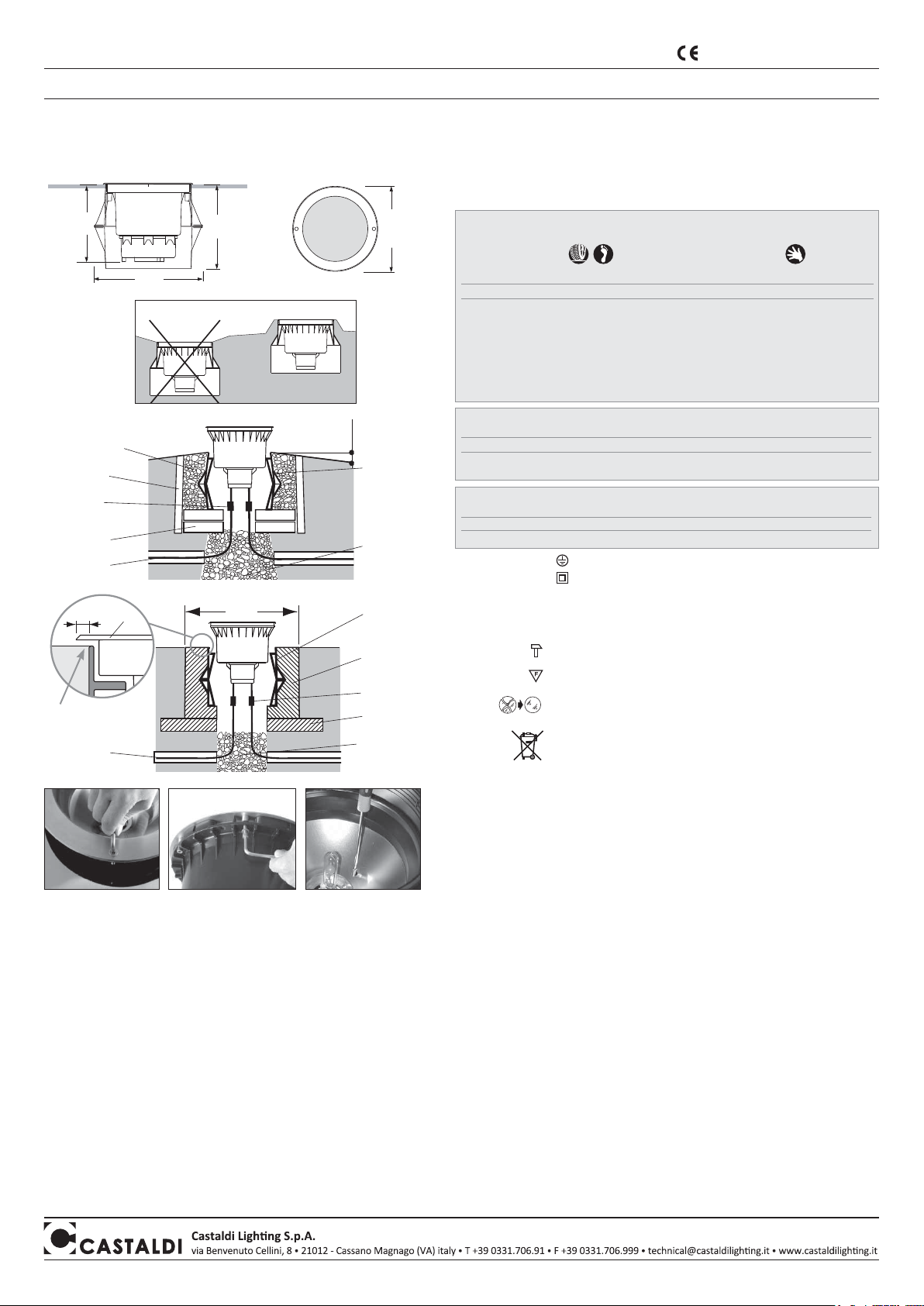
Castaldi Lighting D44K/T3-L Series Instruction Manual

60 cm
Versioni in Classe I : richiedono il cavo di messa a terra
Versioni in Classe II : non richiedono il cavo di messa a terra
• Non impiegare in aree in cui sono utilizzati spazzaneve.
IP66 - IP67 totalmente protetto contro la polvere e getti d’acqua potenti
può funzionare momentaneamente sommerso
apparecchio idoneo per servizio gravoso,
resistenza all’urto non minore di 6,5 Nm
apparecchio idoneo per montaggio su superfici
normalmente infiammabili
sostituire lo schermo di protezione se danneggiato con
vetro piano float temperato - spessore 10mm
resistente all’urto 6,5Nm secondo EN60598-1
è vietato lo smaltimento come rifiuto urbano
è obbligatoria la raccolta separata a fine vita del prodotto
“Consorzio di appartenenza RAEE: Ecolight.
Registro Nazionale dei Produttori N°: IT08010000000166 ”
MONTAGGIO INTERRATO NON CARRABILE - per un corretto montaggio è necessario procedere come segue:
1) evitare di posizionare l’apparecchio in avvallamenti (fig.1) ove possono formarsi facilmente sacche di
sporcizia e ristagni d’acqua.
Figura 2
2) eseguire un foro (carotatura) nel terreno con diametro di circa 40/50 cm e profondità di circa 80/100 cm.
3) riquadrare la parte superiore del foro inserendo un pozzetto prefabbricato di dimensioni circa 60x60x50 cm.
Il filo superiore pozzetto dovrà risultare di circa 3/4 cm più alto del terreno circostante cui dovrà raccordarsi
con pendenza verso l’esterno per facilitare il deflusso di acqua ed evitare accumuli di sporcizia.
4) riempire la carotatura con mistone di sabbia e ghiaia sino ad una distanza di circa 40 cm dal bordo
superiore pozzetto. Bagnare abbondantemente con canna dell’acqua sino a rifiuto e costipare il mistone
in modo da costituire uno strato sicuramente drenante compatto e omogeneo.
5) sistemare sul fondo del pozzetto così ottenuto quattro mattoni con una cazzuolata di malta onde costituire
una salda base di appoggio per la custodia esterna dell’apparecchio che dovrà risultare sporgente rispetto
al filo pozzetto prefabbricato di circa 2/3 cm.
6) riempire il pozzetto esternamente alla custodia con misto di sabbia e ghiaia ben costipata ed assestata
predisponendo i cavi di linea per l’allacciamento elettrico dell’apparecchio.
MONTAGGIO INTERRATO CARRABILE - procedere come ai precedenti punti 1-2-3-4
5) riferirsi alla figura 3. Eseguire un magrone di cemento su cui appoggiare il blocco di fondazione avendo
cura di lasciare al centro un foro di diametro almeno 20 cm per il drenaggio. Prevedere passaggio cavi.
6) inserire la custodia esterna dell’apparecchio in un blocco di fondazione in calcestruzzo dosato a 200 Kg
di cemento tipo 325 per metro cubo di impasto e avente diametro o lato non minore di 60 cm.
Il filo superiore della cassaforma di alloggiamento apparecchio dovrà essere perfettamente livellato
al piano di pavimento finito come illustrato nel dettagio di fig.3.
ALLACCIAMENTO ELETTRICO
Attenzione: la connessione elettrica deve essere eseguita da un impiantista qualificato.
Attenzione: in caso di danneggiamento dell’apparecchio si può verificare una riduzione del grado di protezione
con conseguente infiltrazione di acqua e perdita di isolamento. Pertanto, si raccomanda di inserire nell’impianto
elettrico una protezione addizionale contro i contatti diretti (ad esempio un interruttore differenziale ad alta
sensibilità). Durante l’installazione rispettare scrupolosamente le norme impiantistiche vigenti.
• Per allacciamento elettrico utilizzare cavo flessibile in gomma <HAR> di diametro adatto sezione 1-1,5mm2.
Gli apparecchi sono forniti completi di uno spezzone di cavo H07RN-F già collegato e collaudato a tenuta,
per un rapido e sicuro collegamento alla linea elettrica utilizzare il connettore ns codice ACS/CR1 o sistema
equivalente che garantisca almeno il grado IP67.
ROTAZIONE OTTICA per tutti i modelli è possibile ruotare l’ottica di ±45° sul piano orizzontale, allentando la
vite sul bordo del riflettore ove presente. Solo per i modelli
D44K/T3-MB - D44/T3-MB e D44K/T3-NB - D44/T3-NB
è possibile basculare l’ottica fino a 6° e per i modelli
D44K/T3-L… - D44/T3-L…
è possibile basculare l’ottica
fino a 15°, sul piano verticale avvitando la vite indicata in figura 6.
Ø 315
380
257
280
riempimento di sabbia
e ghiaia ben costipata
custodia esterna
apparecchio
sottofondo
drenante di
sabbia e ghiaia
bagnato con
canna sino
a rifiuto, ben
assestato e
costipato
blocco di
calcestruzzo
magrone
fig. 2
fig. 3
fig. 1
strato drenante
mattoni di appoggio
fissati con una
cazzuolata di malta
connessione
accessorio ACS/CR1
pozzetto
prefabbricato
60x60x50cm circa
cavi di linea
SI
NO
384 cm
cavi di linea
custodia
esterna
apparecchio
8 mm
telaio
MI/1661 - 5aedizione - 04/2014
istruzioni di montaggio - manutenzione D44-tellux/T3 D44K-tellux/T3
fig. 4
fig. 5
fig. 6
connessione
accessorio ACS/CR1
Apparecchi impiegabili in aree ad accesso limitato, secondo EN60598-2-13, temp. MAX vetro 100°C
Apparecchi impiegabili solo in aree normalmente non accessibili, secondo EN60598-2-13,
con temperatura del vetro MAGGIORE
di 100°C
versioni Classe I
D44K/T3-F42-26W
D44K/T3-F42-32W
D44K/T3-F42-42W
D44K/T3-L…
D44K/T3-MH35MB
D44K/T3-MH70MB
D44K/T3-MH35NB
D44K/T3-MH70NB
versioni Classe II
D44/T3-F42-26W
D44/T3-F42-32W
D44/T3-F42-42W
D44/T3-L…
D44/T3-MH35MB
D44/T3-MH70MB
D44/T3-MH35NB
D44/T3-MH70NB
temp. max vetro con ta 25°C
53° C
58° C
68° C
55° C
70° C
65° C
CON deflettore termico D44/T3-DT
55° C
73° C
50° C
75° C
versioni Classe I
D44K/T3-MH70MB
D44K/T3-MH70NB
versioni Classe II
D44/T3-MH70MB
D44/T3-MH70NB
temp. max vetro con ta 25°C
90° C
90° C
CON deflettore termico D44/T3-DT
versioni Classe I
D44K/T3-MH150… versioni Classe II
D44/T3-MH150…
temp. max vetro con ta 15°C
140° C
CON deflettore termico D44/T3-DT
125° C
Apparecchi impiegabili in tutte le aree accessibili, secondo EN60598-2-13, con esclusione
delle aree dove è richiesta temperatura vetro max 40°C
carrabile e pedonabile , con temperatura MASSIMA del vetro 75°C
resistenza al carico statico 20 kN.
Caratteristiche apparecchio e significato dei simboli riportati in etichetta:
• apparecchio d’illuminazione per montaggio incassato a terra in ambienti interni ed esterni. Idoneo a
sopportare il carico di autoveicoli con pneumatici in gomma, peso massimo statico e dinamico: 3500Kg
RICAMBIO LAMPADA - MANUTENZIONE
• togliere tensione prima di effettuare ogni tipo di manutenzione.
• staccare l’apparecchio dalla custodia esterna e portarlo a bordo terreno. (fig.4)
• pulirlo accuratamente prima di aprirlo aiutandosi con un grosso pennello e con un panno umido.
• svitare il telaio (fig.5) e procedere al ricambio lampada attenendosi strettamente al tipo e alla
potenza indicati in targa. Leggere attentamente le istruzioni fornite dal costruttore della lampada
per il suo corretto uso.
• il ricambio lampada va effettuato con la massima attenzione evitando che possano sporcarsi la
guarnizione di tenuta e la battuta di appoggio relativa. Verificare lo stato della guarnizione e se
deformata sostituirla. Assicurarsi che la guarnizione risulti perfettamente centrata nella sua sede.
Per fare ciò è indispensabile che l’apparecchio sia con bocca in posizione orizzontale.
• è essenziale effettuare una periodica ed efficiente pulizia del vetro e della superficie esterna
dell’apparecchio su cui non debbono formarsi depositi di terra e sporcizia. Tali depositi
provocano infatti pericolosi surriscaldamenti impedendo la corretta emissione di luce e la corretta
dissipazione termica.
• attenzione, in caso di danneggiamento del cavo H07RN-F, rottura dello schermo,
infiltrazioni di acqua l’apparecchio non può essere utilizzato. Disconnetterlo dalla linea
elettrica e contattare la nostra Azienda o la nostra organizzazione di vendita per la
sostituzione/riparazione.
VERSIONE LED - RISCHIO DI GRUPPO 2:
ATTENZIONE: possibile emissione di radiazione ottica da questo prodotto. Non guardare la
sorgente luminosa potrebbe danneggiare gli occhi. Per l’acquisto del circuito LED rivolgersi
alla nostra Azienda o ai nostri rivenditori. L’intervento di sostituzione deve essere eseguito
da un impiantista qualificato.
Controllo qualità: In caso di reclamo mettersi in contatto con la nostra
azienda o con la nostra organizzazione di vendita citando l’ordine di acquisto
e il numero di matricola che contrassegna l’apparecchio.
prodotto rispondente ai requisiti previsti
dalle Direttive Comunitarie Europee
filo superiore
cassaforma
livellato al piano di
pavimento finito
NOTA BENE: Le presenti istruzioni di montaggio devono obbligatoriamente essere consegnate all’utente finale affinché conosca le corrette modalità di manutenzione e ricambio lampada. È vietata
qualsiasi manomissione e/o trasformazione dell’apparecchio che deve essere installato e utilizzato: così come fornito e in conformità alle Norme Impianti Nazionali. Installazioni non conformi fanno
decadere ogni forma di garanzia, l’Azienda non risponde dei danni causati da un errato montaggio. PRECAUZIONI DI MONTAGGIO - AVVERTENZE! Poichè l’apparecchio è carrabile e incassato
nel terreno, l’installazione deve essere fatta con la massima cura rispettando scrupolosamente le istruzioni di montaggio qui precisate. • L’apparecchio è testato e collaudato alla penetrazione
dell’acqua. • È opportuno posizionare e installare l’apparecchio chiuso, con lampada già montata e correttamente orientato onde evitare l’ingresso di sporcizia e compromettere la tenuta stagna.

60 cm
384 cm
8 mm
Version in Class I : earth required
Version in Class II : earth not required
• Do not install in areas where snowplows are used.
IP66 - IP67
totally dust-proof and watertight against powerful water jets
will operate if occasionally submerged
heavy duty: can withstand impacts up to 6,5 Nm
mounting on normally inflammable surfaces allowed
replace the protection screen if damaged
with a plane float tempered glass – thickness 10 mm,
shock resistant 6,5Nm according to EN60598-1
getting rid of as urban waste forbidden
separate collection is mandatory when
the product is at the end of its life
EMBEDDED INSTALLATION WITHOUT PASSAGE OF VEHICLES
for correct assembly, proceed as follows: 1) avoid positioning the fixture in areas of subsidence (pict.1) where
dirt and stagnant water can accumulate.
Picture 2
2) make a hole (boring) in the ground with a diameter of approximately 40/50 cm and approximately
80/100 cm deep.
3) square the upper part of the hole by inserting a prefabricated pit of approximately 60x60x50 cm.
The upper edge of the pit must be about 3/4 cm higher than the surrounding ground to which it must be
connected with an outer slope for the run-off of water and to avoid the accumulation of dirt.
4) backfill the hole with a mixture of sand and gravel up to a distance of about 40 cm from the upper edge
of the pit. Hose with plenty of water until refusal and tamp the mixture in such a way as to form a
compact and homogenous draining layer.
5) use bricks on the bottom of the pit in order to form a solid support base for the outer casing of the fixture
which must protrude about 2/3 cm with respect to the edge of the prefabricated pit.
6) backfill the pit around the casing with a mixture of well tamped and set sand and gravel, arranging the
cables for the electrical connection of the fixture.
EMBEDDED INSTALLATION WITH PASSAGE OF VEHICLES
proceed as in the above points 1-2-3-4.
5) refer to pict.3, prepare lean concrete cement on which to place the block of concrete, taking care
to leave a hole with a diameter of at least 20 cm for drainage. Provide for the passage of electrical wires.
6) insert the outer casing of the fixture into a concrete foundation block, batched at 200 kg of 325 type
cement per cubic metre of mixture. The block must have a diameter (or side) of not less than 60 cm.
Line up carefully the upper edge of the outer casing with the trampling level as per pict. 3.
ELECTRICAL CONNECTION
Important
:the electrical connection must be carried out by a skilled
electrician
.
Important: in the case of damage of the appliance, there may be a reduction in the degree of protection with
consequent infiltration of water and loss of insulation. Therefore, additional protection should be inserted into
the electrical plant against direct contacts (for example a high sensitivity differential switch). During installation,
fully respect the current rules on electrical systems.
• For the electrical connection use a flexible <HAR> rubber cable cross-section 1x1,5mm2. The fixtures
are complete with a piece of H07RN-F cable which is pre-connected and sealed. For a rapid and safe
connection with the electric line use the connector ACS/CR1 or an equivalent system that guarantees at
least the IP67 degree.
OPTICAL ROTATION
for all models, it is possible to turn the optic of
±45°
on the horizontal axis, by loosening
the screw on the border of the reflector, where present. Only for the models
D44K/T3-MB - D44/T3-MB and
D44K/T3-NB - D44/T3-NB
, it is possible to swing the optic up to
6°
only for the models
D44K/T3-L… - D44/T3-L…
it is possible to swing the optic up to
15°,
on the vertical axis by turning on the screw indicated on pict.6
.
installation and maintenance sheet D44-tellux/T3 D44K-tellux/T3
Ø 315
380
257
280
well tamped sand and
gravel backfill
fixture outer
casing
sand and
gravel draining
foundation,
hosed until
refusal, well
set and
tamped
concrete block
lean concrete
pict. 2
pict. 3
pict. 1
draining layer
support bricks
fixed with
a trowel of mortar
connection
accessory ACS/CR1
prefabricated pit
60x60x50cm
approx.
electric cables
YES
NO
electric cables
fixture outer
casing
frame
upper casing
level flushing
to roadside
pict. 4
pict. 5
pict. 6
connection
accessory ACS/CR1
Fixtures that can be utilized in areas with limited access, according to EN60598-2-13, MAX. glass temp. 100°C
Fixtures
that
can be utilized only in normally not accessible areas,
according to
EN60598-2-13,
glass temp. more than
100°C
version Class I
D44K/T3-F42-26W
D44K/T3-F42-32W
D44K/T3-F42-42W
D44K/T3-L…
D44K/T3-MH35MB
D44K/T3-MH70MB
D44K/T3-MH35NB
D44K/T3-MH70NB
version Class II
D44/T3-F42-26W
D44/T3-F42-32W
D44/T3-F42-42W
D44/T3-L…
D44/T3-MH35MB
D44/T3-MH70MB
D44/T3-MH35NB
D44/T3-MH70NB
max. glas Temp. ta 25°C
53° C
58° C
68° C
55° C
70° C
65° C
with thermal deflector D44/T3-DT
55° C
73° C
50° C
75° C
version Class I
D44K/T3-MH70MB
D44K/T3-MH70NB
version Class II
D44/T3-MH70MB
D44/T3-MH70NB
max. glas Temp. ta 25°C
90° C
90° C
with thermal deflector D44/T3-DT
version Class I
D44K/T3-MH150… version Class II
D44/T3-MH150…
max. glas Temp. ta 15°C
140° C
with thermal deflector D44/T3-DT
125° C
Fixtures that can be utilized in all accessible areas, according to EN60598-2-13,
with exclusion of the areas where max. glass temp. 40°C is requested
Pedestrian and drive over, with max. glass temp. of 75°C
20kN static load resistance.
Features and meaning of the symbols shown on the label:
• lighting appliance for indoor and outdoor ground-recessed installation. Capable of withstanding the load
of motor vehicles with inflatable tyres pumped with air, maximum weight static or dynamic: 3500Kg
RELAMPING - MAINTENANCE
• cut off power from the mains before carrying out any type of maintenance.
• remove the fixture from the outer casing and take it to the edge of the ground. (pict.4)
• carefully clean the fixture before opening it by the help of a big brush and of a humid cloth.
• unscrew the frame (pict.5) and proceed with changing the lamp, respecting fully type and
power of lamp as shown on the label. Carefully read the instructions supplied by the lamp
manufacturer for its correct use.
• great care must be taken when changing the lamp, avoiding dirtying the waterproof seal and
relative support ledge. Check the gasket and replace it if deformed. Make sure that the gasket
is dead-centered in its housing.
For a correct operation it is necessary to arrange the unit so that its mouth is horizontal.
• it is essential a frequent cleaning of the glass and of the outer surface of the fixture to avoid
build up of mud and dirtiness resulting in dangerous overheating due to uncorrect light and
heath dissipation.
• important: in the event of damage to the H07RN-F cable, breakage of the screen,
infiltration of water, the appliance cannot be used. Disconnect it from the mains supply
and contact our company or our sales organization for replacement/repair.
LED VERSION - RISIKOGRUPPE 2:
WARNUNG: dieses Produkt kann gefährliche optische Strahlungen emittieren. Schauen
Sie nicht in die Lichtquelle, kann Ihre Augen schädigen. Zum Einkaufen der Led-
Lampe, wenden Sie sich an unsere Firma oder an unsere Verkaufsorganisation. Die
Auswechselung muss von einem qualifizierten Installateur angefertigt werden.
Quality control: Should you have any complaint please get in touch with
our company or its sales organization. Please give the number of your
order as well as the serial number that recognizes the fixture.
product in compliance with the requirements
of the European Community Directories
NB: These assembly instructions must be given to end users for correct maintenance and so that they know how to change the bulb. The appliance must not be tampered with or transformed and
it must be installed and used as supplied and in compliance with the National Rules on Installations. Any non-compliant installations will invalidate all forms of guarantee. The company cannot be
held responsible for damage caused by incorrect assembly. PRECAUTIONS FOR ASSEMBLY - IMPORTANT! As it is a drive-over ground-recessed appliance, great care must be taken in installation,
scrupulously following the assembly instructions specified here. • The appliance is tested for the penetration of water. • The appliance should be positioned and installed when closed, with the bulb
already mounted and correctly adjusted in order to avoid dirt entering and compromising its watertightness.

60 cm
384 cm
8 mm
instructions de montage - entretien D44-tellux/T3 D44K-tellux/T3
Ø 315
380
257
280
remplir de sable et
gravier bien compact
puits extérieur
appareil
sous-fond
drainant
de sable et
de graviers
baignés jusqu’à
constitution
d’un mélange
bien compact
bloc de béton
mortier maigre
fig. 2
fig. 3
fig. 1
couche drainante
briques d’appui
fixées par du mortier
connexion
accessoire ACS/CR1
puits préfabriqué
60x60x50cm
câbles de ligne
OUI
NON
câbles de ligne
puits extérieur
appareil
telaio
fig. 4
fig. 5
fig. 6
connexion
accessoire ACS/CR1
Appareils
qui peuvent être utilisés dans les zones à admission limité, selon EN60598-2-13,
temp. MAX du verre 100°C
Appareils
qui peuvent être utilisés seulement dans les zones normalement inaccessibles,
selon EN60598-2-13,
temp. du verre SUPÉRIEURE de
100°C
version Classe I
D44K/T3-F42-26W
D44K/T3-F42-32W
D44K/T3-F42-42W
D44K/T3-L…
D44K/T3-MH35MB
D44K/T3-MH70MB
D44K/T3-MH35NB
D44K/T3-MH70NB
version Classe II
D44/T3-F42-26W
D44/T3-F42-32W
D44/T3-F42-42W
D44/T3-L…
D44/T3-MH35MB
D44/T3-MH70MB
D44/T3-MH35NB
D44/T3-MH70NB
temp. Max verre avec ta 25°C
53° C
58° C
68° C
55° C
70° C
65° C
AVEC déflecteur thermique D44/T3-DT
55° C
73° C
50° C
75° C
version Classe I
D44K/T3-MH70MB
D44K/T3-MH70NB
version Classe II
D44/T3-MH70MB
D44/T3-MH70NB
temp. Max verre avec ta 25°C
90° C
90° C
AVEC déflecteur thermique D44/T3-DT
version Classe I
D44K/T3-MH150… version Classe II
D44/T3-MH150…
temp. Max verre avec ta 25°C
140° C
AVEC déflecteur thermique D44/T3-DT
125° C
Appareils qui peuvent être utilisés dans toutes les zones accessibles, selon la norme EN60598-2-13,
mais pas dans les zones particulaires qui nécessitent une température du verre max 40°C
piétinable et carrossable , avec une temp. MAX. du verre de 75°C
résistent à la charge statique 20kN.
Caractéristiques de l’appareil - signification des symboles portés sur l’étiquette:
• appareil d’éclairage pour montage encastré dans le sol pour l’intérieur et l’extérieur. Apte à supporter le
charge de véhicules avec des pneus gonflés avec air, poids maximum statique ou dynamique: 3500Kg.
CHANGEMENT DE LA LAMPE - ENTRETIEN
• Couper la tension avant d’effectuer ce genre d’opération.
• séparer l’appareil du puits extérieur et le mettre au bord du terrain. (fig.4)
• nettoyer soigneusement l’appareil avant de l’ouvrir. S’aider avec un gros pinceau et un chiffon humide.
• dévisser le cadre (fig.5) et faire le changement de lampe en s’en tenant strictement au type et à la
puissance indiquée sur l’étiquette. Lire attentivement les instructions de montage fournies par le
fabricant de la lampe pour sa correcte utilisation.
• le réchange de la lampe doit être effectué avec une très grande attention en évitant de salir le joint
et sa base d’appui. Contrôler l’état du joint et le remplacer si deformé en s’assurant que le joint
soit parfaitement mis à sa place. Il est indispensable pour faire ceci que la bouche de l’appareil
soit en position horizontale.
• l est indispensable d’effectuer régulièrement un nettoyage du verre et de la surface extérieure
de l’appareil sur lequels il ne doit jamais se former des dépôts de terre ou de saletés. Ces dépôts
provoquent en fait un sur échauffement empéchant une émission correcte de la lumière et une bonne
dissipation thermique.
• attention: l’appareil ne peut pas être utilisé en cas de détérioration du câble H07RN-F,
de rupture de l’écran, d’infiltrations d’eau. Le débrancher et contacter le fabricant ou le
S.A.V. pour le remplacement/réparation.
VERSION LED - GROUPE DE RISQUE 2:
ATTENTION: possible émissions de rayonnements optiques de cet appareil. Ne regardez pas
la source de lumière, peut endommager vos yeux. Pour le remplacement du circuit imprimé
complet de Led, prions contacter notre Société ou nos distributeurs. Le changement doit etre
fait par un électricien qualifié.
Contrôle qualité: Pour toute réclamation, nous vous prions de bien vouloir
contacter notre société ou notre organisation de vente, en citant le numéro
de commande et le numéro qui contremarque l’appareil.
Version en Classe I : mise à la terre nécessaire
Version en Classe II : mise à la terre pas nécessaire
• Ne installer pas en surfaces ou les chasse-neige sont utilisés.
IP66 - IP67
totalement protégé contre la poussière et violents jets d’eau
étanche pour immersion temporaire
prévu pour situations difficiles,
peut supporter des chocs pas inférieurs à 6,5 Nm
adapté pour utilisation sur des surfaces
normalement inflammables
Remplacer l’écran de protection si endommagé
avec du verre plan float trempé – épaisseur 10mm,
résistant aux chocs 6,5Nm selon EN60598-1
il est interdit l’élimination comme ordure urbaine
le rammassage separé est obligatoir lorsque le produit
est à la fin de sa vie
MONTAGE ENCASTRÉ SANS PASSAGE DE VOITURES
pour un montage correct il est nécessaire de procéder comme suit: 1) éviter de positionner l’appareil en
dépression (fig.1) la où peuvent facilement se former des dépôts de poussière et des retenues d’eau
Figure 2
2) faire un trou dans le sol d’un diamètre d’environ 40/50 cm et une profondeur d’environ 80/100 cm.
3)
mettre d’équerre la partie supérieure du trou en insérant un puits pré-fabriqué de dimensions environ 60x60x50
cm.
La partie supérieure du puits devra être installé 3/4 cm au-dessus du terrain environnant auquel devra être
raccordé avec une inclinaison vers l’extérieur afin de faciliter le débit d’eau et eviter l’accumulation de saleté
.
4) remplir le trou avec un mélange de sable et de graviers jusqu’à environ 40 cm du bord supérieur du
puits. Baigner abbondamment avec de l’eau jusqu’à ce que le mélange constitue une strate suffisamment
compacte et homogène.
5) poser au fond du puits des briques afin de constituer une base d’appui pour le puits extérieur de l’appareil qui
devra dépasser le puits préfabriqué d’environ 2/3 cm.
6) remplir le trou à l’extérieur du puits avec un mélange de sable et de graviers bien compact en prédisposant
les câbles de ligne pour l’alimentation électrique de l’appareil.
MONTAGE ENCASTRÉ POUR PASSAGE DE VOITURES
procéder comme aux points 1-2-3-4
5) se référer à la figure 3, faire une base de ciment sur laquelle s’appuie le bloc de beton en ayant soin de
laisser au centre un trou de diamètre 20 cm pour le drainage. Prévoir le le passage des câbles électriques.
6) insérer le puits extérieur de l’appareil dans un bloc de fondation en béton dosé à 200 Kg de ciment type 325
par mètre cube de mélange ayant un diamètre (ou un côté) non inférieur à 60 cm .
Le bord supérieur du puits extérieur de l’appareil devra être parfaitement nivelé au plan du sol selon le detail
de fig.3.
BRANCHEMENT ÉLECTRIQUE
Attention
: la connexion électrique doit être effectuée par un électricien qualifié.
Attention: en cas de
détérioration de l’appareil, une réduction du degré de protection peut se produire avec, par conséquent, une
infiltration d’eau et une réduction de l’isolement. Il est donc recommandé de prévoir dans l’installation électrique
une protection supplémentaire contre les contacts directs (par exemple, un interrupteur différentiel haute
sensibilité). Pendant l’installation, respecter scrupuleusement les normes en vigueur pour les installations.
• Pour la connexion électrique utiliser seulement un câble flexible de caoutchouc <HAR> d’une section de
1x1,5mm 2. Les appareils sont équipés avec un pièce de câble HO7RN déjà connexe et étanche. Pour un
rapide et sur connexion à la ligne électrique utiliser le connecteur ACS7CR1 ou un système similaire pour
garantir au moins le grade IP67.
ROTATION OPTIQUE pour tous les models, il est possible de tourner l’optique de ±45° sur le plan horizontal,
en desserrant la vis au bord du réflecteur, où présente. Seulement pour les modèles D44K/T3-MB -
D44/T3-MB et D44K/T3-NB - D44/T3-NB, il est possible de basculer l’optique jusqu’à 6° pour les modèles
D44K/T3-L… - D44/T3-L… il est possible de basculer l’optique jusqu’à 15°, sur le plan vertical en vissant
le vis indiqué en fig. 6.
produit avec caractéristiques selon les
Directives Communautaires Européennes
fil supérieur du
chassis nivelé au
plan du plancher
NOTA BENE: Remettre obligatoirement ces instructions de montage à l’usager final pour qu’il connaisse les modalités correctes de maintenance et de remplacement d’ampoule. Toute modification
et/ou transformation est interdite sur l’appareil, qui doit être installé et utilisé tel qu’il est fourni et conformément aux Normes d’Installation Nationales. Une installation non conforme provoque
la déchéance de toutes formes de garantie et la compagnie ne répondra pas des dommages provoqués par un montage erroné. PRECAUTIONS DE MONTAGE - AVERTISSEMENTS! Comme
l’appareil est charretier et encastré dans le terrain, exécuter l’installation avec le plus grand soin en respectant scrupuleusement les instructions de montage spécifiées ici. • L’appareil est essayé
et testé contre la pénétration de l’eau. • Mettre l’appareil en position et l’installer fermé avec l’ampoule déjà en place, et correctement orienté pour empêcher l’entrée éventuelle de saleté et ne
pas en compromettre l’étanchéité.

60 cm
Ø 315
380
257
280
384 cm
Version in Klasse I : benötigt ein Erdungskabel
Version in Klasse II : benötigt kein Erdungskabel
• Nicht in Arealen installieren wo Schneeräumer eingesetzt werden.
IP66 - IP67 Absolut staubdicht Schutz bei Untertauchen
und wasserdicht gegen stärke Wasserstrahle
Belastbarkeit: kann Stösse von einer Kraft bis 6,5 Nm ertragen
Geeignet für Montage auf normal entflammbaren Befestigungsflächen
Wenn beschädigt, der Schutzschirm mit float gehärtetem
Flachglass austauschen, 10mm Dicke und 6,5Nm
stoßfest nach EN60598-1.
Das Entsorgen im Hausmüll ist verboten!
Bei Ablauf der Lebensdauer bitte beachten:
Abfalltrennung ist Pflicht
MONTAGE UNTER DER ERDE, NICHT BEFAHRBAR
für eine richtige Montage, muss wie folgt vorgegangen werden: 1) das Gerät nicht in Senkungen installieren
(Abb.1), in denen sich lecht Schmutz und Feuchtigkeit ansammeln kann.
Abbildung 2
2) in dem Boden ein Loch mit einem Durchmesser von 40/50 cm und eine Tiefe von 80/100 cm graben.
3) Den oberen Teil des Loches mit einer vorgefertigten Verschalung mit einem Ausmass von 60x60x50 cm
verstärken. Der obere Rand der Verschalung muss ca. 3/4 cm aus dem Boden herausragen und abfallende
Flanken nach aussen haben, um das Abfliessen des Wassers zu erleichtern und das Ansammeln von
Schmutz zu vermeiden.
4) Das Loch mit einer Mischung aus Sand und Kies bis zu 40 cm unter dem oberen Rand der
Verschalung füllen. Reichlich mit Wasser begiessen, damit sich die Mischung richtig festsetzt und eine
wasserdurchlässige kompakte und gleichmässige Schicht bildet.
5) Auf den so erhaltenen Boden des Loches vier Backsteine mit einer Schicht Mörtel einsetzen, um eine feste
Basis für das Chassis des Gerätes zu schaffen, die 2/3 cm aus Vorgefertigtem Einbauschacht.
6) Das Loch um das Chassis herum mit einer Mischung aus Sand und Kies ausfüllen, die gut festgedrückt
werden muss, wobei gleichzeitig die Linienkabel des Gerätes für die elektrische Verbindung ausgerichtet
werden müssen.
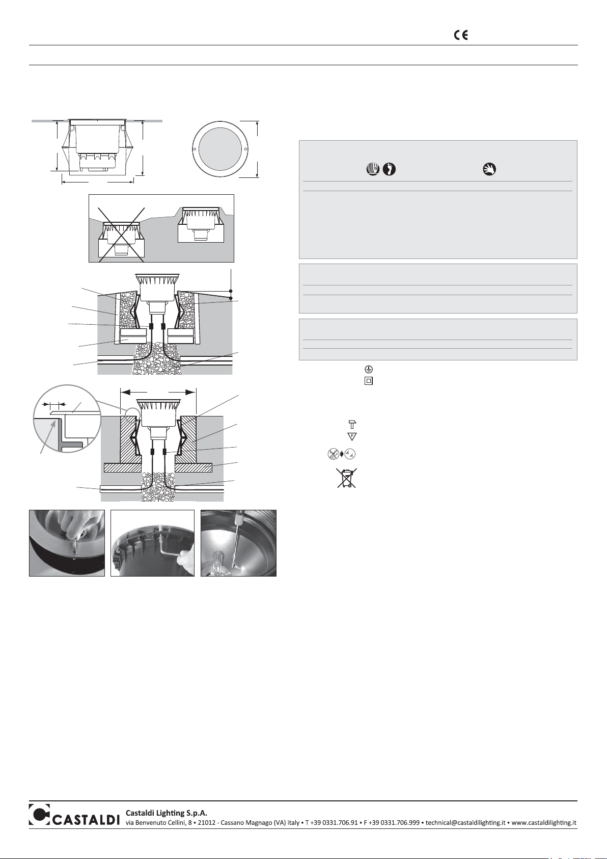
MONTAGE UNTER DER ERDE, BEFAHRBAR - Die Anweisungen 1-2-3-4 wie oben angegeben befolgen
5) vgl. Abbildung 3, Legen Sie ein Bett aus leichtem Zement an, auf dem Sie den Betonblock aufsetzen;
achten Sie dabei darauf, in der Mitte ein Loch mit Durchmesser von mindestens 20 Cm fürs Dränage.
Ein Durchgang für die Kabeln vorsehen.
6)
Das Chassis des Gerätes in einen Zementboden einlassen, der auf 200 Kg Zement des Typs 325 pro
Kubikmeter Mischung bemessen ist.
Der Zementblock muss einen Durchmesser (oder eine Seite) von
mindestens 60 cm haben.
Der obener Rand des aussenes Schachtels mit der Fußgängeroberflache
aufmerksam anpassen.
(Abb.3)
ELEKTROANSCHLUSS
Achtung: die elektrische Verbindung muss von einem qualifizierten Installateur durchgeführt werden.
Achtung: bei Beschädigung der Leuchte kann der Schutzgrad beeinträchtigt werden mit daraus folgendem
Eindringen von Wasser und Isolierungsverlust. Es wird daher empfohlen, die elektrische Anlage mit einem
Zusatzschutz gegen direkte Kontakte (z. B. mit einem hochempfindlichen Differentialschalter) auszurüsten.
Bei der Installation die geltenden anlagentechnischen Vorschriften unbedingt befolgen.
• Für die elektrische Verbindung ein flexibles <HAR> Gummikabel mit Querschnitt von 1x1,5mm2benützen.
Die Geräte sind mit einem Stück HO7RN-F Kabel ausgestattet, der schon verbunden und getestet ist. Für
eine schnelle und sichere Verbindung an der elektrischen Leitung die ACS/CR1 Anschlussstelle oder eine
ähnliche verwenden die einen Grad von mindestens IP67 gewährleistet.
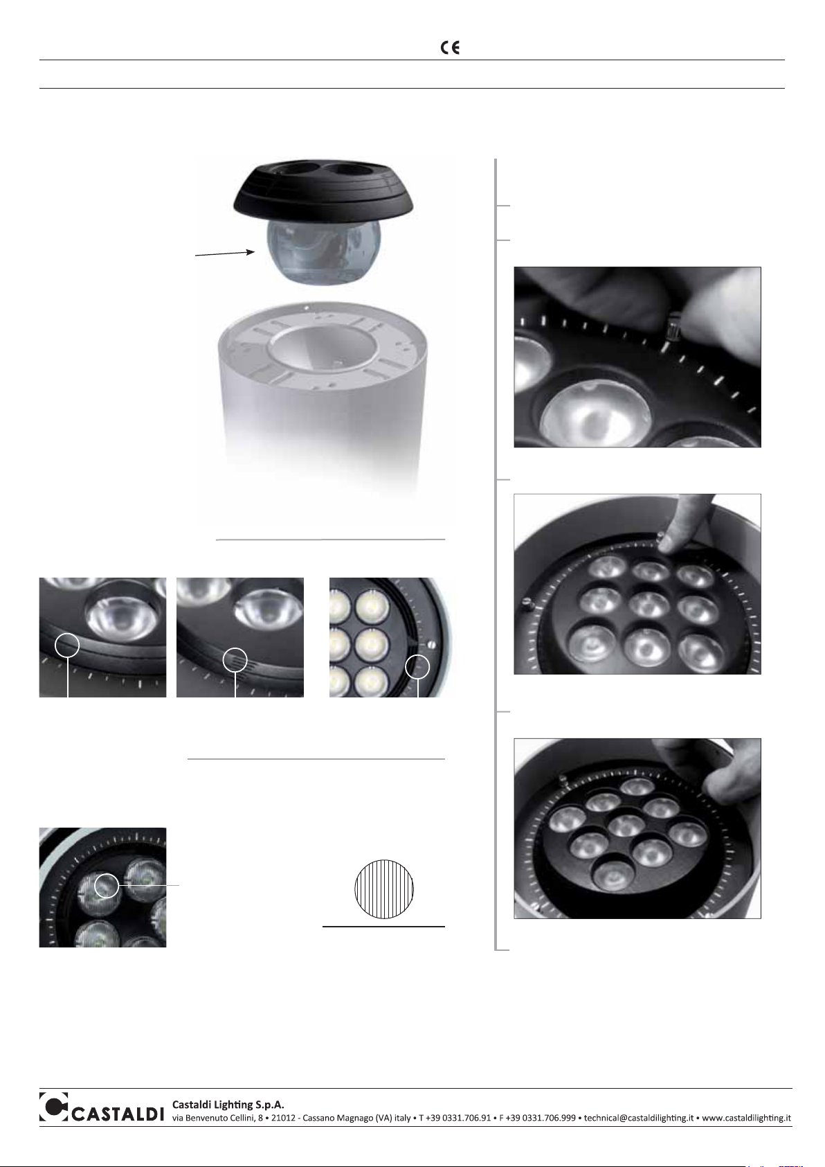
OPTISCHE ROTATION Für alle Modelle, est ist möglich den Optik von ±45°beim die Schraube auf der Kante
des Reflektors lockern, wo anwesend. Nur für Modelle
D44K/T3-MB - D44/T3-MB
und
D44K/T3-NB - D44/T3-NB
,
es ist möglich den Optik bis 6° um, für Modelle
D44K/T3-L… - D44/T3-L…
, es ist möglich den Optik bis 15°
um der senkrechter Achse zu schwingen beim den in Abb. 6 gezeicheneten Schraub Einschrauben.
Montageanleitung - Instandhaltung D44-tellux/T3 D44K-tellux/T3
Füllung mit gut verdichtetem
Sand und Kies Äusseres
Chassis des
Gerätes
Dränagegrund
aus mittels
Bewässerung
festgesetztem
Sand und Kies,
gut gestampft
und verdichtet
Betonblock
Magerschicht
Abb. 2
Abb. 3
Abb. 1
dränierende
Schicht
Basisbacksteine
mit einer Schicht
Mörtel fixiert
Anschluss an
Zubehör ACS/CR1
vorgefertigter
Einbauschacht
ca. 60x60x50cm
Leitungskabeln
JA
NEIN
Äusseres
Chassis des
Gerätes
Abb. 4
Abb. 5
Abb. 6
Anschluss an
Zubehör ACS/CR1
Apparate die in Arealen mit eingeschränktem Zugang verwendet werden können,
nachEN60598-2-13,
MAX. Glastemperatur 100°C
Apparate die nur in normalerweise nicht zugänglichen Arealen verwendet werden dürfen, nach
EN60598-2-13,
Glastemperatur ÜBER
100°C
version Klasse I
D44K/T3-F42-26W
D44K/T3-F42-32W
D44K/T3-F42-42W
D44K/T3-L…
D44K/T3-MH35MB
D44K/T3-MH70MB
D44K/T3-MH35NB
D44K/T3-MH70NB
version Klasse II
D44/T3-F42-26W
D44/T3-F42-32W
D44/T3-F42-42W
D44/T3-L…
D44/T3-MH35MB
D44/T3-MH70MB
D44/T3-MH35NB
D44/T3-MH70NB
max. Glastemperatur ta
25°C
53° C
58° C
68° C
55° C
70° C
65° C
MIT thermishen Deflektor D44/T3-DT
55° C
73° C
50° C
75° C
version Klasse I
D44K/T3-MH70MB
D44K/T3-MH70NB
version Klasse II
D44/T3-MH70MB
D44/T3-MH70NB
max. Glastemperatur ta
25°C
90° C
90° C
MIT thermishen Deflektor D44/T3-DT
version Klasse I
D44K/T3-MH150… version Klasse II
D44/T3-MH150…
max. Glastemperatur ta
25°C
140° C
MIT thermishen Deflektor D44/T3-DT
125° C
Apparate die in allen zugänglichen Arealen verwendet werden können außer,
nach EN60598-2-13, in den speziellen Arealen wo die maximale Glastemperatur von 40°C ist.
Begeh- und befahrbar mit max. Glastemperatur 75°C
Statische Belastbarkeit 20 kN.
Eigenschaften - Bedeutung der Symbole auf dem Typenschild:
• Begehbare Bodeneinbauleuchte für den Innen - und Außenbereich. Hält das Gewicht von Kraftfahrzeugen
mit Gummireifen aufgepumpt mit Luft, aus maximalen Gewicht statisches oder dynamisches: 3500Kg
Qualitätskontrolle: Sollten Sie Reklamationen haben, wenden Sie sich
an unsere Firma oder an unsere Verkaufsorganisation unter Angabe des
Bestelldatums und der Kennummer des Geräts.
Leitungskabeln
LAMPENWECHSEL - WARTUNG
• vor jeglichem Wartungseingriff Spannung abschalten.
• Das Gerät von dem äusseren Chassis entfernen und auf Bodenhöhe bringen. (Abb.4)
• Das Gerät mit einem grossen Pinsel und einem feuchten Tuch sorgfältig säubern, bevor es
geöffnet wird.
• Den Rahmen (Abb.5) abschrauben und die Lampe ersetzen. Dabei muss die auf dem Schild
angegebene Leistung unbedingt beachtet werden. Die Angaben des Herstellers der Lampe genau
lesen, um diese richtig zu benutzen.
• Das Ersetzen der Lampe muss mit grosser Aufmerksamkeit ausgeführt werden, um zu
vermeiden, dass die Dichtungen und der entsprechende Anschlag verschmutzen. Die
Komponenten anordnen und sich vergewissern, dass die Dichtung sauber, nicht verformt und
einwandfrei sitzt. Bei diesem Vorgang unbedingt darauf achten, dass die Leuchte mit der Öffnung
in horizontaler Stellung und nicht geneigt ist. Den Zustand der Dichtung überprüfen und bei
Verformung auswechseln.
• Das Glas der Leuchte sowie alle Aussenflächen des Gerätes müssen regelmässig gereinigt werden,
so dass Ablagerungen von Schmutz ausgeschlossen sind. Solche Ablagerungen beinhalten die Gefahr
einer Überhitzung und verhindern die Vorschriftsmässige Lichtabstrahlung und Wärmedissipation.
• Achtung: im Fall von beschädigtem Kabel H07RN-F, Bruch des Schutzschirmes oder
Eindringen von Wasser darf die Leuchte nicht verwendet werden. Schalten Sie die Leuchte
vom Strom ab und kontaktieren Sie unser Unternehmen oder unsere Verkaufsorganisation
für den Austausch oder die Reparatur.
LED VERSION - RISIKOGRUPPE 2:
WARNUNG: dieses Produkt kann gefährliche optische Strahlungen emittieren. Schauen Sie
nicht in die Lichtquelle, kann Ihre Augen schädigen. Zum Einkaufen der Led-Lampe, wenden
Sie sich an unsere Firma oder an unsere Verkaufsorganisation. Die Auswechselung muss
von einem qualifizierten Installateur angefertigt werden.
Das Produkt entspricht den Richtlinien
der Europäischen Gemeinschaft
8 mm
Rahmen
obener Faden des
Schachtels auf der
Strasseroberfläche
nivelliert
NOTA BENE: Vorliegende Montageanleitungen müssen auf jeden Fall dem Endverbraucher übergeben werden, damit dieser über die korrekten Wartungs- und Lampenaustauschmodalitäten
informiert ist. Jegliches Aufbrechen und/oder Änderung der Leuchte ist verboten. Die Leuchte muss wie geliefert und entsprechend den anlagentechnischen Landesvorschriften montiert und
verwendet werden. Nichtentsprechende Installationen führen zum Verfall von jeglicher Garantie. Das Unternehmen übernimmt keine Verantwortung für Schäden, die durch fehlerhafte Montage
verursacht sind. VORSICHTSMAßNAHMEN FÜR DIE MONTAGE - HINWEISE Da die Leuchte befahrbar und in den Boden eingelassen ist, muss die Montage mit größter Sorgfalt unter strenger
Befolgung der hier erwähnten Montageanleitungen durchgeführt werden. • Die Leuchte ist auf Wassereindringung getestet und geprüft. • Es empfiehlt sich, die Leuchte geschlossen mit bereits
montierter Lampe und korrekter Ausrichtung zu positionieren und zu installieren, um den Eintritt von Schmutz zu vermeiden und die Dichtigkeit nicht zu beeinträchtigen.

Chiudere il prodotto / Close the fixture
Fissare VOLVENDO avvitando le viti /
fix VOLVENDO tighting the screws
Controllo qualità - In caso di reclamo mettersi in contatto con la nostra azienda o con la nostra organizzazione di vendita citando l’ordine di acquisto e il numero
di matricola che contrassegna l’apparecchio. - Quality control: Should you have any complaint please get in touch with our company or its sales organization.
Please give the number of your order as well as the serial number that recognizes the fixture.
MI/1888 - 2aedizione - 11/2014
istruzioni di montaggio - installation sheet
prodotto rispondente ai requisiti previsti dalle Direttive Comunitarie Europee
product in compliance with the requirements of the European Community Directories
VOLVENDO
SISTEMA DI PUNTAMENTO ORBITALE BREVETTATO
PATENTED ORBITAL AIMING SYSTEM
PRECISIONE / PRECISION
PUNTAMENTO / ADJUSTING
WALL WASHING - EB
WALL
Inclinazione/Inclination
Aprire il prodotto /Open the fixture
Sbloccare VOLVENDO allentando le viti /
Unblock VOLVENDO loosing the screws
Puntare il fascio / Adjust the beam
Rotazione/ Rotation
zigrinatura delle lenti
perpendicolari rispetto al muro /
lens knurling right to the wall
L’orientamento orbitale consente l’utilizzo dell’ottica ellittica (EB) per il Wall
Washing radente ad apparecchio installato vicino la parete / The orbital aiming
allows the use of the elliptical (EB) optics for wall washing effect when the fixture is
installed near the wall.
5° 5°1°
N
Per maggiori informazioni fare riferimento alle istruzioni di montaggio dedicate all’apparecchio.
For further information refer to product instruction booklet.
LED RISCHIO DI GRUPPO 2- ATTENZIONE: POSSIBILE EMISSIONE DI RADIAZIONE OTTICA EMESSA DA QUESTO PRODOTTO. NON GUARDARE LA SORGENTE
LUMINOSA POTREBBE DANNEGGIARE GLI OCCHI. IL CIRCUITO LED NON È SOSTITUIBILE DALL’UTENTE. CONTATTARE LA NOSTRA AZIENDA O LA NOSTRA
RETE DI VENDITA.
LED RISK GROUP 2 - CAUTION: POSSIBLY HAZARDOUS OPTICAL RADIATION EMITTED FROM THIS PRODUCT. DO NOT STARE AT OPERATING LAMP. MAY
BE HARMFUL TO THE EYE. LED CIRCUIT CAN’T BE REPLACED BY THE USER. GET IN TOUCH WITH OUR COMPANY OR ITS SALES ORGANIZATION.
Il funzionamento è
assicurato dal perfetto
contatto tra le superfici
sferiche, garantito dalla
presenza di un compound
termico per il trasferimento
del calore che non deve
essere rimosso.
For the unit to operate
properly, there must be
good contact between the
spherical surfaces; this is
assured by the presence
of a thermo-conductive
compound which must not
be removed.

Refermer le produit / Das Produkt schließen
Fixer le VOLVENDO en serrant les vis /
VOLVENDO durch Festdrehen der Schrauben fixieren
Contrôle qualité: Pour toute réclamation, nous vous prions de bien vouloir contacter notre société ou notre organisation de vente, en citant le numéro de
commande et le numéro qui contremarque l’appareil. - Qualitätskontrolle: Sollten Sie Reklamationen haben, wenden Sie sich an unsere Firma oder an unsere
Verkaufsorganisation unter Angabe des Bestelldatums und der Kennummer des Geräts.
instructions de montage - Montageanleitung
produit avec caractéristiques selon les Directives Communautaires Européennes
Das Produkt entspricht den Richtlinien der Europäischen Gemeinschaft
VOLVENDO
NOUVEAU SYSTÈME ORBITAL BREVETÉ
NEUES PATENTIERTES DREH-/SCHWENKSYSTEM
PRECISION / PRÄZISION
PUNTAMENTO / ADJUSTING
WALL WASHING - EB
MUR/ WANDFLUTER
Inclinaison /Neigung um
Ouvrir le produit /Das Produkt öffnen
Débloquer l’appareil VOLVENDO en desserrant les vis /
VOLVENDO durch Lösen der Schrauben entriegeln
Orienter le faisceau / Den Strahler ausrichten
Rotation / Drehung um
cannelures des lentilles
perpendiculaires au mur /
senkrechte zur mauer
verlaufende linsenrillung
L’orientation orbitale permet l’utilisation de l’optique elliptique (EB) pour obtenir un
effet lèche-mur en cas d’appareil installé près du mur / Das Dreh-/Schwenksystem
kann für die elliptische Optik (EB) zum Einsatz kommen, und sorgt dadurch für
eine fokussierte Optik der Wandfluter, die in der Nähe einer Wand installiert sind.
5° 5°1°
GROUPE DE RISQUE LED 2 - ATTENTION: LES RAYONNEMENTS OPTIQUES DANGEREUX À EMISSION DE CE PRODUIT. NE PAS REGARDER LA LAMPE
D’EXPLOITATION. PEUT ÊTRE NOCIF POUR LES YEUX. CIRCUIT CONDUIT NE PEUT PAS ÊTRE REMPLACÉ PAR L’UTILISATEUR. ENTREZ EN CONTACT AVEC
NOTRE ENTREPRISE OU SON ORGANISATION DE VENTE. LED RISIKOGRUPPE 2 - ACHTUNG: MÖGLICHERWEISE GEFÄHRLICHE OPTISCHE STRAHLUNG VON
DIESEM PRODUKT EMITTIERT. NICHT BEI BETRIEBS LAMPE SCHAUEN NICHT. KANN SCHÄDLICH FÜR DIE AUGEN SEIN. LED-SCHALTUNG KANN NICHT VOM
BENUTZER AUSGETAUSCHT WERDEN.NEHMEN SIE KONTAKT MIT UNSEREM UNTERNEHMEN ODER VERTRIEBSORGANISATION ICT.
Pour plus d’informations, reportez-vous aux instructions de montage du produit.
Für weitere Informationen siehe Produkt-Anleitung.
Le fonctionnement est assuré
par le contact parfait entre
les surfaces sphériques,
garanti par la présence d’un
composé thermique pour le
transfert de la chaleur qui ne
doit pas être retiré.
Die Funktionstüchtigkeit wird
durch den perfekten Kontakt
zwischen den kugelförmigen
Oberflächen garantiert und
durch die Wärmeleitpaste, die
nicht entfernt werden darf.

D44/T2-GP
Aprire l’apparecchio e inserire la griglia come indicato in figura 2.
Orientarla nella direzione prescelta, considerando che la griglia
scherma nel piano trasversale alle lamelle.
D44/T3-GP
Aprire l’apparecchio e inserire la griglia come indicato in figura 3.
L’orientamento della griglia rispetto alla lampada deve essere fisso
come in figura.
Ruotare l’apparecchio nella posizione idonea ad assicurare la
schermatura nella desiderata direzione di osservazione.
D44/Q3-GP
Aprire l’apparecchio e inserire la griglia come indicato in figura 4.
L’orientamento della griglia rispetto alla lampada deve essere fisso
come nelle figure sotto riportate.
Ruotare l’apparecchio nella posizione idonea ad assicurare la
schermatura nella desiderata direzione di osservazione.
istruzioni di montaggio - manutenzione D44-tellux/GP
MI/1651- 3aedizione - 02/2015
Montageanleitung - Instandhaltung D44-tellux/GP
fig. 2
fig. 3
fig. 4
F42-F57
piano di schermatura
piano di schermatura OSSERVATORE
OSSERVATORE
OSSERVATORE
F242 MH70MF MH70AS
Controllo qualità: In caso di reclamo mettersi
in contatto con la nostra azienda o con la
nostra organizzazione di vendita citando
l’ordine di acquisto e il numero di matricola che
contrassegna l’apparecchio.
Qualitätskontrolle: Sollten Sie Reklamationen
haben, wenden Sie sich an unsere Firma oder an
unsere Verkaufsorganisation unter Angabe des
Bestelldatums und der Kennummer des Geräts.
NOTA BENE
Tutti gli apparecchi possono ruotare di 90° in 90° entro la custodia esterna, posizionandosi
quindi nel modo più opportuno in relazione alle istruzioni che seguono.
Le operazioni di apertura e chiusura devono essere eseguite con scrupolo e in condizioni
di massima pulizia, evitando di sporcare la guarnizione e la sua battuta di appoggio.
Assicurarsi altresì che la guarnizione risulti correttamente inserita entro la sua sede come
in fig. 1.
fig. 1
ZU BEACHTEN
Alle Leuchtenkörper können innerhalb des äußeren Gehäuses in 90°-Schritten gedreht
werden um die bestmögliche Position zu finden gemäß beiliegender Montageanweisungen.
Die Leuchte sollte sorgfältig geöffnet und geschlossen werden in einer sauberen Umgebung
um Verschmutzungen der Dichtung und des Gehäuses zu vermeiden.
Stellen Sie sicher, dass die Dichtung im Gehäuse richtig montiert ist. (Abb. 1)
Abb. 1
D44/T2-GP
Öffnen der Leuchte und Einfügen des Lamellenrasters. (Abb. 2)
Ausrichten in die gewünschte Richtung unter Berücksichtigung,
dass die Lamellen des Gitters über Kreuz abschirmen.
D44/T3-GP
Öffnen der Leuchte und Einfügen des Lamellenrasters. (Abb. 3)
Ausrichten und Befestigen des Rasters gemäß Lage des
Leuchtmittels, wie in Zeichnung dargestellt.
Drehen des Gehäuses in die bestmögliche Position, um sicher zu stellen, dass
die Abblendrichtung mit der benötigten Beobachterrichtung übereinstimmt.
D44/Q3-GP
Öffnen der Leuchte und Einfügen des Lamellenrasters. (Abb. 4)
Ausrichten und Befestigen des Rasters gemäß Lage des
Leuchtmittels, wie in unten angegebener Zeichnung dargestellt.
Drehen des Gehäuses in die bestmögliche Position, um sicher zu stellen, dass
die Abblendrichtung mit der benötigten Beobachterrichtung übereinstimmt.
Abb. 2
Abb. 3
Abb. 4
F42-F57
Abschirmrichtung
Abschirmrichtung
Abschirmrichtung BEOBACHTER
BEOBACHTER
BEOBACHTER
F242 MH70MF MH70AS
Das Produkt entspricht den Richtlinien
der Europäischen Gemeinschaft prodotto rispondente ai requisiti previsti
dalle Direttive Comunitarie Europee

installation and maintenance sheet D44-tellux/GP
D44/T2-GP
Open the fixture and put in the grill as per picture 2.
Adjust it on the chosen direction, taking into account that the grill
screens crosswise its blades.
D44/T3-GP
Open the fixture and put in the grill as per picture 3
The grill adjustment respect to the lamp must be fix as per the
drawing.
Rotate the fixture in the most suitable position to ensure the
screening towards the needed direction to observe.
D44/Q3-GP
Open the fixture and put in the grill as per picture 4
The grill adjustment respect to the lamp must be fix as per the
drawings here below.
Rotate the fixture in the most suitable position to ensure the
screening towards the needed direction to observe.
pict. 2
pict. 3
pict. 4
F42-F57
screening plane
screening plane
screening plane OBSERVER
OBSERVER
OBSERVER
F242 MH70MF MH70AS
Quality control: Should you have any complaint
please get in touch with our company or its sales
organization. Please give the number of your order
as well as the serial number that recognizes the
fixture.
NOTICE
All the fixtures can rotate from 90° to 90° inside the external box to find the most suitable
position according to the following instructions.
The fixture must be carefully opened and closed on a clean environment, avoiding to dirty
the gasket and its housing.
Make sure that the gasket is properly mounted in its housing as per picture 1.
pict. 1
Contrôle qualité: Pour toute réclamation, nous
vous prions de bien vouloir contacter notre société
ou notre organisation de vente, en citant le numéro
de commande et le numéro qui contremarque
l’appareil.
NOTA BENE
Tous les luminaires peuvent rouler de 90° en 90° dans leur étui extérieur, prénant ensuite
la position la plus favorable toujours suivant les instructions qui suivent.
Il faut ouvrir et fermer le luminaire avec soin, dans conditions de haute propreté, évitant
surtout de salir le joint et son logement.
Il faut aussi s’assurer que le joint résulte correctement placé dans son logement,
tel que en figure 1.
fig. 1
instructions de montage - entretien D44-tellux/GP
D44/T2-GP
Ouvrir le luminaire et placer la grille comme indiqué en figure 2.
Orienter la grille même dans la direction décidée, tenant compte
que la grille voile dans le plan transversal aux lamelles.
D44/T3-GP
Ouvrir le luminaire et placer la grille comme indiqué en figure 3.
L’orientation de la grille par respect à la lampe est fixe selon
le dessin.
Rouler le luminaire dans la position la plus convenable pour assurer
la protection dans la direction désiree pour observer.
D44/Q3-GP
Ouvrir le luminaire et placer la grille comme indiqué en figure 4.
L’orientation de la grille par respect à la lampe est fixe selon les
dessins ci-dessous.
Rouler le luminaire dans la position la plus convenable pour assurer
la protection dans la direction désiree pour observer.
fig. 2
fig. 3
fig. 4
F42-F57
plan de protection
plan de protection
plan de protection OBSERVATEUR
OBSERVATEUR
OBSERVATEUR
F242 MH70MF MH70AS
product in compliance with the requirements
of the European Community Directories produit avec caractéristiques selon les
Directives Communautaires Européennes
This manual suits for next models
15
Other Castaldi Lighting Landscape Lighting manuals

Castaldi Lighting
Castaldi Lighting D44K-Tellux T2 Instruction Manual

Castaldi Lighting
Castaldi Lighting D17-tarzan/sistem1 9L Instruction Manual

Castaldi Lighting
Castaldi Lighting D44K/Q3-L Series Instruction Manual

Castaldi Lighting
Castaldi Lighting D44-tellux/P01 Instruction Manual

Castaldi Lighting
Castaldi Lighting D43 tau/3 Instruction Manual
Popular Landscape Lighting manuals by other brands

AMP Lighting
AMP Lighting VariantPro AAL-1028-0-B-BZ Installation & maintenance guide

Volt
Volt VHS-6719-BBZ installation instructions

LIGMAN
LIGMAN TA-80563 installation manual

LIGMAN
LIGMAN MALTA 1 installation manual

AMP Lighting
AMP Lighting AHS-7004-4-B-BZ Installation & maintenance guide

SLV
SLV 1006408 instruction manual