Castell KSSE User manual

While every effort has been made to ensure the accuracy of the information provided, no liability can be taken for any errors or omission.
Castell Safety International Limited reserves the right to alter speci cations and introduce improvements without prior notice.
www.castell.com
1 of 7
U-KSSE-001-E Issue 1
KSSE Multi Key Solenoid Controlled Switch
User Manual - Original Language Version
The KSSE is a solenoid controlled, multi-key electrical switch
for the controlled isolation of low current. This product is used
where the controlled isolation of a machine needs to take place,
i.e. where a robot has to nish a cycle prior to isolation and
where multiple entry points to the protected area are required.
The solenoid is continuously rated, and its position is electrically
monitored. This type of isolator should be used for short term,
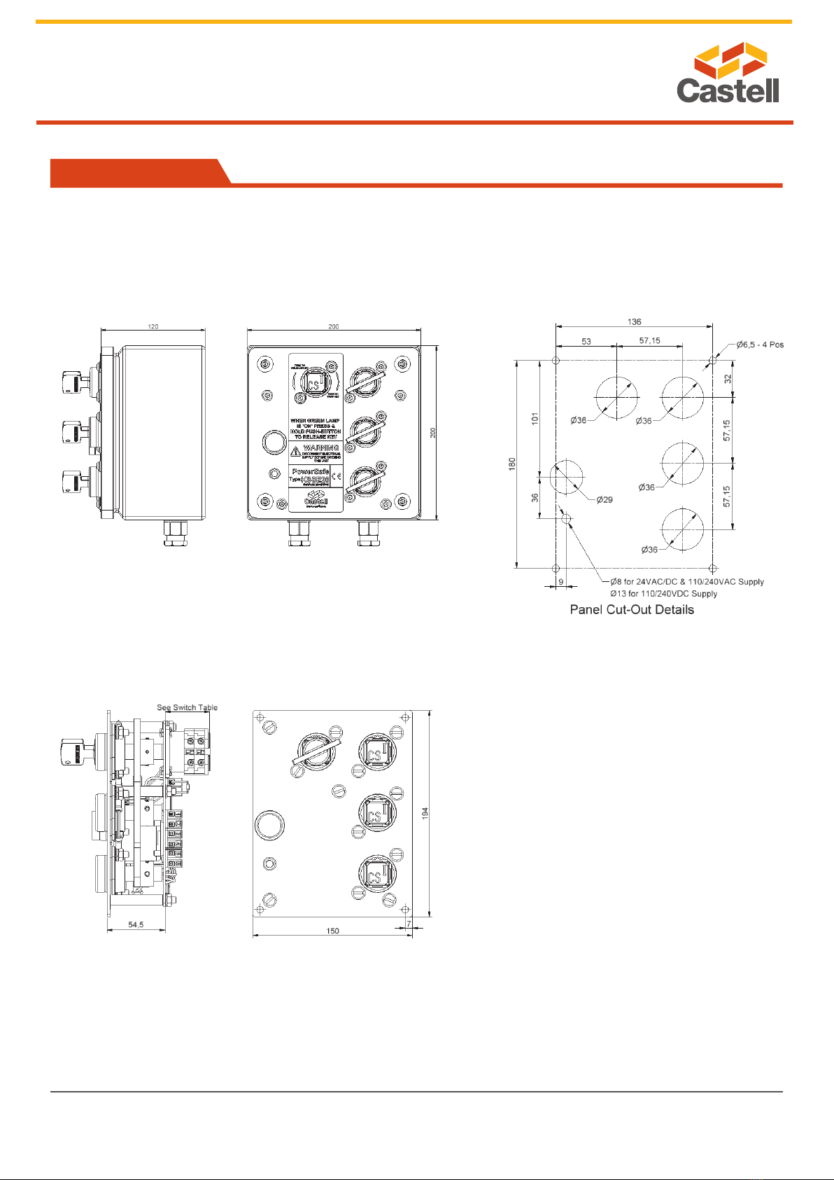
off load isolation. The unit is supplied capable of being mounted
into an existing panel or for surface mounting within its own IP65
rated lockable steel enclosure. The KSSE is manufactured from
either brass or stainless steel making it ideal for use in standard
or harsh corrosive environments.
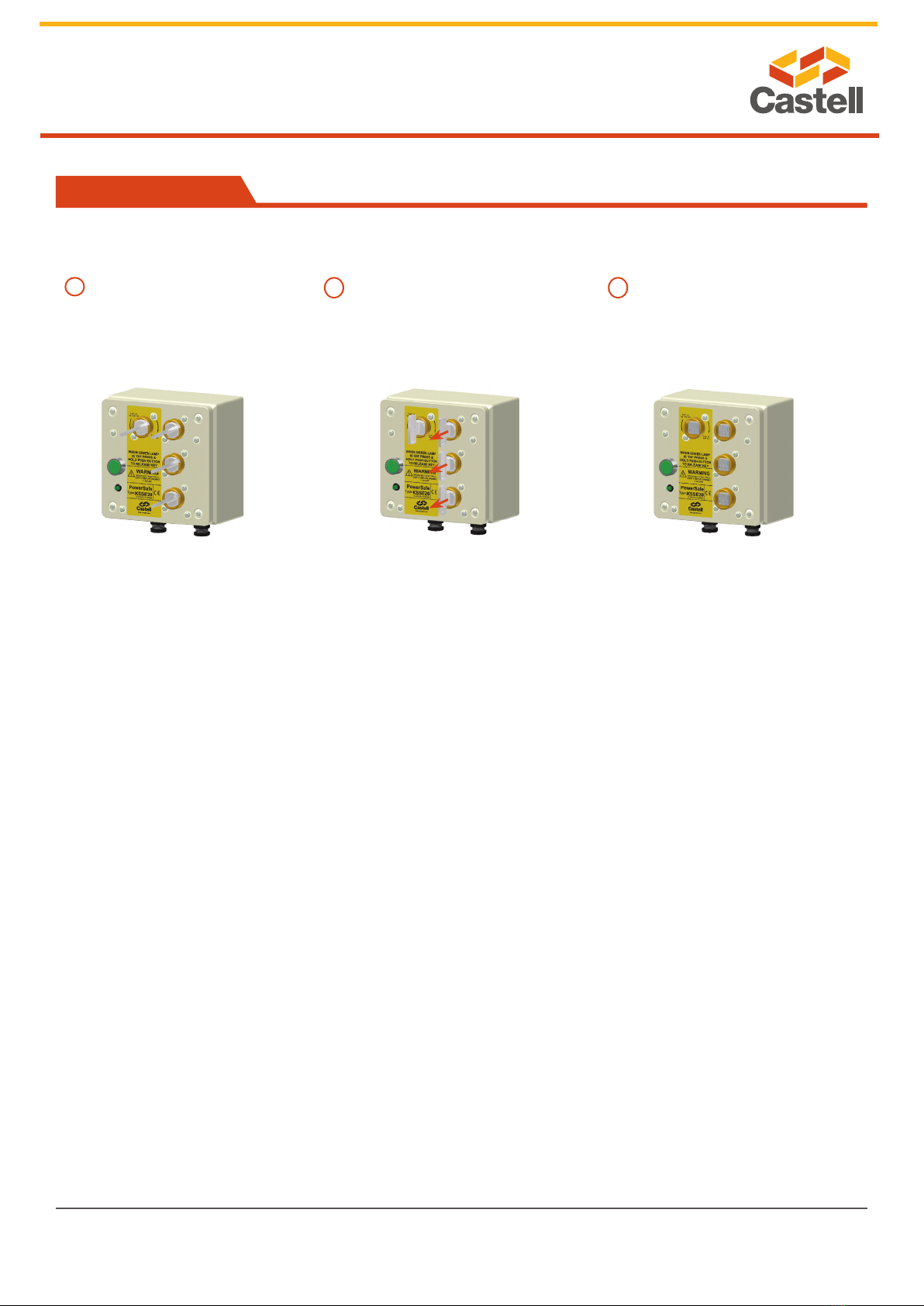
Operation
E20-FSS-3D-F-C/O4-110A
Castell multi key solenoid controlled switches are typically used for machine isolation in applications where a machine
has to nish a cycle prior to isolation.
1. While the isolation key is free, the power is on. Personnel keys are trapped.
2. By inserting and turning the isolation key in the KSSE, the contact condition changes switching the power off. Once the
machine has fi nished the cycle, a signal is sent to the KSSE to energise the solenoid and an LED illuminates. The personnel
keys can now be released by pushing the button. These keys can be taken by personnel to unlock the doors in the machine
area.
3. The Isolation Keys stay trapped ensuring power is off until all personnel keys are replaced in the KSSE unit.
123
Isolation Key is free while power
is on, solenoid is de-energised.
Personnel keys are trapped.
Insert and turn isolation key to switch
power off. Once external signal is
received (LED illuminates), push the
button to de-energize the solenoid and
release personnel keys.
Power is off, isolation key is
trapped and personnel keys are
free.
KSSE multi key solenoid controlled switch, exchange key condition

While every effort has been made to ensure the accuracy of the information provided, no liability can be taken for any errors or omission.
Castell Safety International Limited reserves the right to alter speci cations and introduce improvements without prior notice.
www.castell.com
2 of 7
U-KSSE-001-E Issue 1
KSSE Multi Key Solenoid Controlled Switch
User Manual - Original Language Version
Operation
1. While all keys are trapped, the switch for the main power supply is closed enabling the power supply.
2. By turning and releasing the keys, the contacts condition changes switching the power off. Once the machine has fi nished
the cycle, a signal is sent to the KSSE to energise the solenoid and an LED illuminates. The Keys can now be released by
pushing the button. These keys should be taken by the personnel to unlock the doors in the machine area.
3. The power is off until all keys are replaced in the KSSE unit and turned, switching the contact condition to open.
KSSE multi key solenoid controlled switch, double key condition
123
All keys are trapped while power is
on, solenoid is de-energised.
Turn and release all keys to change the
condition of the contacts interrupting
power supply. Once external signal is
received (LED illuminates), push the
button to energize the solenoid and
release the keys.
While all keys are free, the power
supply is interrupted.

While every effort has been made to ensure the accuracy of the information provided, no liability can be taken for any errors or omission.
Castell Safety International Limited reserves the right to alter specications and introduce improvements without prior notice.
www.castell.com
3 of 7
U-KSSE-001-E Issue 1
KSSE Multi Key Solenoid Controlled Switch
User Manual - Original Language Version
Usage
Installation
Maintenance
The KSSE multi key solenoid controlled switch is designed to be part of a safety system and is used to isolate the power
releasing a key which is then used to gain access to a hazardous area via an access interlock such as the AI, AIE or Salus.
The KSSE multi key solenoid controlled switch is not designed for security purposes.
No hazardous substances were used in the manufacture of this product. The product can be disposed of in standard waste.
Back of panel units should be mounted to a at surface using suitable fasteners. Please refer to drawing on page 5 for more
details). The lock face should be sealed to the panel for ingress protection.
Cables should be connected to the switch in accordance with the applicable wiring diagrams. Ensure that the unit is bonded for
earth continuity (see drawing on page 5 for more installation details).
IMPORTANT:
The interlock should be mounted using anti-tamper fasteners to prevent unauthorised removal.
The KSSE range of multi key solenoid controlled switches must be installed by a competent and qualied person who
has read and understood these instructions. Please retain this document in your technical le.
Periodic visual checks should be carried out by the site manager / safety ofcer.
Do not lubricate lock barrel with oil or grease, use CK Dry Powder Graphite if necessary.
In case of defects beeing detected please contact your nearest Castell Support Department for further actions.
Please see Contact section for contact details.

While every effort has been made to ensure the accuracy of the information provided, no liability can be taken for any errors or omission.
Castell Safety International Limited reserves the right to alter speci cations and introduce improvements without prior notice.
www.castell.com
4 of 7
U-KSSE-001-E Issue 1
KSSE Multi Key Solenoid Controlled Switch
User Manual - Original Language Version
Technical Data
Temperature rating -25°C ice free to +55°C
Type of mounting Surface (with enclosure) or panel mount using suitable fasteners (please refer to drawing on page 4
for more details)
Weight 4 kg (2 lock portions unit)
Material Brass/Stainless steel
Power isolation 20A
Switch approvals BS,UL,CSA & VDE
MTTF Certifi cation Available on request
We, the manufacturers, declare that the components, detailed herein and placed on the market, comply with all the essential
health and safety requirements applying to them.
Empowered signatory:
Mr T.C. Whelan
Managing Director
EC-Declaration
Application
A typical application of KSSE multi key solenoid controleld
switch is machine guarding. It is usually used in combination
with an access interlock such as the Salus for part body
access or an AIE access interlock with an exchange key for
full body access control.
The KSS breaks the machine safety circuit, ensuring a
machine is shut down once the isolation key is inserted
and turned into the unit. Once the machine has completed
the cycle, an external signal is received by the solenoid,
which is indicated by an illuminated LED. Activating the
green button on the KSSE will enable the personnel keys to
be turned and removed ensuring the power is locked out.
The keys can then be taken to the AIE double key access
interlocks to enable access to the machine.
The machine cannot be restarted until all doors are closed,
and all personnel keys returned to the KSSE multi key
solenoid controlled switch.
KSSE
Solenoid Controleld Switch AIE Access Interlocks

While every effort has been made to ensure the accuracy of the information provided, no liability can be taken for any errors or omission.
Castell Safety International Limited reserves the right to alter specications and introduce improvements without prior notice.
www.castell.com
5 of 7
U-KSSE-001-E Issue 1
KSSE Multi Key Solenoid Controlled Switch
User Manual - Original Language Version
Drawing
Dimensions:
in mm
Note: For safe mounting, use security screws
KSSE

While every effort has been made to ensure the accuracy of the information provided, no liability can be taken for any errors or omission.
Castell Safety International Limited reserves the right to alter specications and introduce improvements without prior notice.
www.castell.com
6 of 7
U-KSSE-001-E Issue 1
KSSE Multi Key Solenoid Controlled Switch
User Manual - Original Language Version
Wiring Diagram
KSSE, Wiring Diagram DC
KSSE, Wiring Diagram AC

While every effort has been made to ensure the accuracy of the information provided, no liability can be taken for any errors or omission.
Castell Safety International Limited reserves the right to alter speci cations and introduce improvements without prior notice.
www.castell.com
7 of 7
U-KSSE-001-E Issue 1
KSSE Multi Key Solenoid Controlled Switch
User Manual - Original Language Version
Wiring Diagram
Contact Information
Castell Safety International Ltd.
The Castell Building
217 Kingsbury Road
London, England NW9 9PQ
t: +44 (0) 20 8200 1200
f: +44 (0) 20 8905 9378
Castell Safety International Ltd.
Oskar-Jäger-Strasse 137
50825 Köln
Germany
t: +49 (0) 221 1649 794
f: +49 (0) 221 1649 795
Castell Interlocks Inc.
Suite 800
150 N Michigan Avenue,
Chicago, Illinois 60601
USA
t: +1.312.360.1516
f: +1.312.268.5174
Castell Safety China
Building 1, No. 123,
Lane 1165, Jindu Road,
Minhang District,
Shanghai 201108, China.
t: +86 21 61519023
f: +86 21 61519030
Order Information
Product Type 1 2 3 4 5 6 7 8 9 10
Part Number E - - -- -
Example E 20 -FS B -1 D -F-CC 4 -110 A
Isolation Key Symbol
(exchange key condition)
Primary Key Symbol
(double key condition)
Personnel Key Symbol
(exchange key condition)
Secondary Key Symbol
(double key condition
A1
12
B1
11 O R O R
1Isolation 20 amps (standard)
2Lock portion type FS (1) / Q (1)
3Material B = Brass / S = Stainless steel
4Secondary (additional) lock portion(s) 1 / 2 / 3 / 4 / 5 or 6 secondary lock portions
5Key condition
E = Exchange key condition /
D = Double key condition (simulataneous removal of all
keys)
6Mounting P = Panel mount (back of board) / F = Front of board
mount, with enclosure
7Contacts arrangement in normal position CO = NO/NC arrangement (contacts closed/opened)/
CC = NC arrangement (contacts closed)
8Number of contacts 4 / 6 (standard)
9Control voltage 110 / 24 / 240 (standard)
10 Current VAC / VDC
11
Lock portion symbol:
Isolation key (for exchange key condition)
Primary key (for double key condition)
FS (1) up to 3 characters / Q (1) up to 6 characters
12
Lock portion symbol:
Personnel key (for exchange key condition)
Secondary key(s) (for double key condition)
FS (1) up to 3 characters / Q (1) up to 6 characters
Special construction available upon enquiry
(1) FS - Lock type Q - Lock type
Up to 3 characters Up to 6 characters
Table of contents