Technical Data
Temperature rating -25 °C ice free to 55 °C
Type of mounting Surface or panel mount using suitable fasteners (please refer to drawing on page 4 for more details)
Weight
KS20: Front of board mount = 0,8 kg / back on board mount = 0,6 kg
KS32: Front of board mount = 0,8 kg / back of board mount = 1 kg
KS63: 1,5 kg
Material Brass/Stainless steel
Enclosure Polycarbonate IP65
Power isolation 20A, 32A, and 63A options available
Motor Isolation (AC Values)
KS20: AC-23A 7.5kW or AC-3 5.5kW
KS32: AC-23A 15kW or AC-3 11kW
KS63: AC-23A 30kW or AC-3 18.5kW
Switch approvals CE, CCC
MTTF Certication Available on request
We, the manufacturers, declare that the components, detailed herein and placed on the market, comply with all the essential
health and safety requirements applying to them.
Empowered signatory:
Mr T.C. Whelan
Managing Director
EC-Declaration
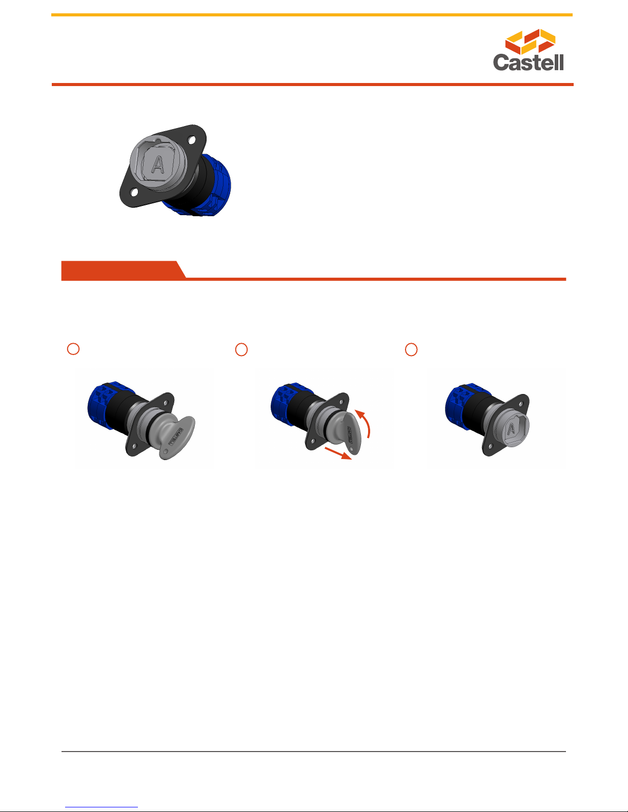
Application
A typical application of KS powersafe electrical switch
is machine guarding. It is usually used in combination
with an access interlock such as the Salus for part body
access or an access interlock with an exchange key for
full body access control such as AIE.
The KS breaks the machine safety circuit, ensuring
a machine is shut down when the key is turned and
removed. The key can then be taken to the Salus
automativ access interlock to enable access to the
machine.
The machine cannot be restarted until the door is closed,
the bolt is trapped in the access interlock and the key is
removed and taken to the KS key switch.
KS20 Key Switch Salus Access Interlock