Castell KSS User manual

KSS Solenoid Controlled Switch
User Manual - Original Language Version
Operation
S20-FSB-F-CC4-110A
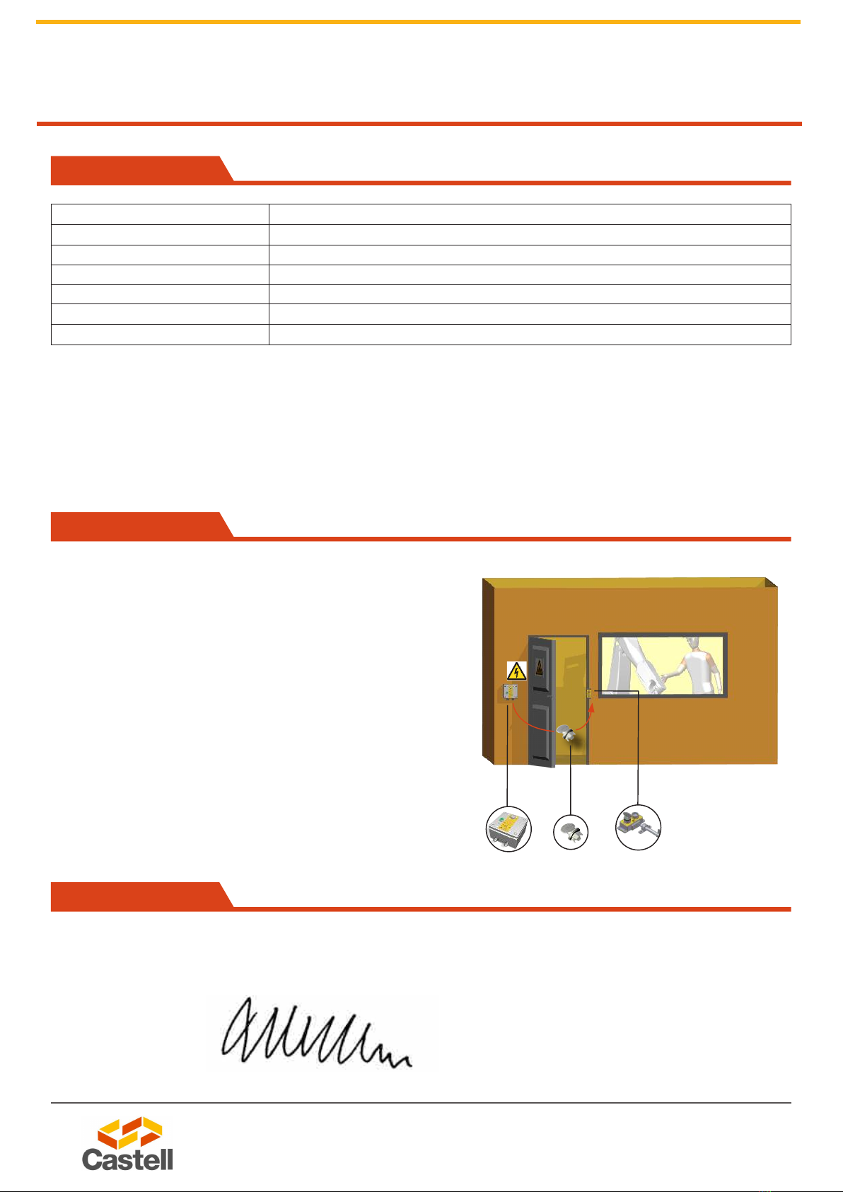
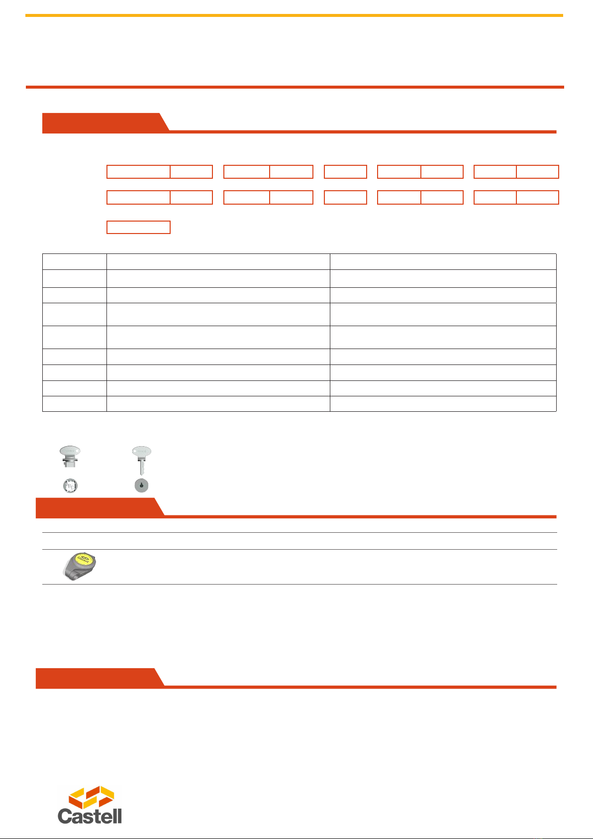
1. While the power is on and a machine is running, the key is trapped in the Solenoid Controlled Switch.
2. To release the key, an external signal must be received to energise the solenoid. With the solenoid energised,
the LED will illuminate to conrm that the key can be removed ensuring the power is off.
3. The key can now be removed and taken to open the door lock and gain access to the machine area.
The KSS is available for different switching loads as KSS20 and KSS32 (20 amps power isolation respectively. See order infor-
mation on page 7 for more details).
The KSS is available with different solenoid voltages as AC: 24, 110 or 240 V or DC: 12, 24, 110, 240 V (see order information on
page 7 for more details).
The KSS comes with 4 or 6 contacts as standard with contacts arrangements as 2NO/2NC, 4NC or 3NO/3NC or 6NC.
The KSS is available as a back of panel mount (BOB) and as a surface mount version with an enclosure (FOB).
1
23
KSS Solenoid Controlled Switch
Key is trapped while power is on,
solenoid is de-energised.
An external signal is received
and LED is illuminated. Push the
button to energise the solenoid
and remove the key.
Solenoid is energised, switch is
locked out and key is free.
The KSS is a heavy-duty solenoid controlled key driven electrical
switch interlock ideal for the controlled isolation or switching
of low current. This product is used where a process can send
a signal to release a key, e.g. a robot has to nish a cycle prior
to isolation. Upon removal of the key, the KSS switch contacts
change to isolate the process. This type of isolator should
be used for short term, off load isolation. The unit is ready
for mounting into an existing panel or for surface mounting
within its own IP65 rated lockable steel enclosure. The KSS
is manufactured from either brass or stainless steel making it
suitable for use in standard or harsh corrosive environments.
The Castell KSS Solenoid Controlled Switch is typically used for machine isolation in applications where a machine has to n-
ish a cycle prior to isolation.
UK Office
5 Caulside Drive, Antrim, BT41 2DU
United Kingdom
TEL: +44 (0) 28 9448 1800
www.pneutrol.com/industrialspares
European Office
Unit 6, Saint Anthony’s Business Park, Ballymount Road, D22 VW95
Ireland
TEL: +353 (0) 1 4373653
www.pneutrol.com/industrialspares
Pneutrol International Limited

KSS Solenoid Controlled Switch
User Manual - Original Language Version
The KSS solenoid controlled switch is designed to be part of a safety system and is used to isolate the power releasing a key
which is then used to gain access to a hazardous area via an access interlock such as the AI, AIE or Salus.
The KSS solenoid controlled switch is not designed for security purposes.
No hazardous substances were used in the manufacture of this product. The product can be disposed of in standard waste.
Usage
Installation
Back of panel units should be mounted to a at surface using suitable fasteners (please refer to drawing on page 4 for more
details). The lock face should be sealed to the panel for ingress protection.
Cables should be connected to the switch in accordance with the applicable wiring diagrams. Ensure that the unit is bonded for
earth continuity (see drawing on page 6 for more installation details).
IMPORTANT:
The interlock should be mounted using anti-tamper fasteners to prevent unauthorised removal.
The KSS range of solenoid controlled switches must be installed by a competent and qualied person who has read and
understood these instructions. Please retain this document in your technical le.
Maintenance
Periodic visual checks should be carried out by the site manager / safety ofcer.
Do not lubricate lock barrel with oil or grease, use CK Dry Powder Graphite if necessary.
In case of defects beeing detected please contact your nearest Castell Support Department for further actions.
Please see Contact section for contact details.
UK Office
5 Caulside Drive, Antrim, BT41 2DU
United Kingdom
TEL: +44 (0) 28 9448 1800
www.pneutrol.com/industrialspares
European Office
Unit 6, Saint Anthony’s Business Park, Ballymount Road, D22 VW95
Ireland
TEL: +353 (0) 1 4373653
www.pneutrol.com/industrialspares
Pneutrol International Limited

KSS Solenoid Controlled Switch
User Manual - Original Language Version
Technical Data
Temperature rating -25°C to +55°C
Type of mounting Surface mount using suitable fasteners (see drawing on page 4-5 for hole details)
Weight 2kg
Material Brass locks with powder coated mild stell enclosure
Power isolation 20A
Switch approvals BS,UL,CSA & VDE or CCC
MTTF Certication Available on request
We, the manufacturers, declare that the components, detailed herein and placed on the market, comply with all the essential
health and safety requirements applying to them.
Empowered signatory:
Mr T.C. Whelan
Managing Director
EC-Declaration
Application
A typical application of KSS solenoid controleld switch
is machine guarding. It is usually used in combination
with an access interlock such as the Salus for part body
access or an access interlock with an exchange key for
full body access control.
The KSS breaks the machine safety circuit, ensuring a
machine is shut down. Once the machine has completed
the cycle, an external signal is received by the solenoid,
which is indicated by an illuminated LED. Activating the
green button on the KSS will enable the key to be turned
and removed ensuring the power is locked out. The key
can then be taken to the AIE access interlock to enable
access to the machine.
The machine cannot be restarted until the door is closed,
the bolt is trapped in the AIE access interlock and the
key is removed and taken to the KSS solenoid controlled
switch.
KSS
Solenoid Controleld Switch AIE Access Interlock
UK Office
5 Caulside Drive, Antrim, BT41 2DU
United Kingdom
TEL: +44 (0) 28 9448 1800
www.pneutrol.com/industrialspares
European Office
Unit 6, Saint Anthony’s Business Park, Ballymount Road, D22 VW95
Ireland
TEL: +353 (0) 1 4373653
www.pneutrol.com/industrialspares
Pneutrol International Limited

KSS Solenoid Controlled Switch
User Manual - Original Language Version
Drawing
Dimensions:
in mm
Note: For safe mounting, use security screws
KSS, panel mount (BOB: back of board)
KSS, surface mounting (FOB: front of board)
UK Office
5 Caulside Drive, Antrim, BT41 2DU
United Kingdom
TEL: +44 (0) 28 9448 1800
www.pneutrol.com/industrialspares
European Office
Unit 6, Saint Anthony’s Business Park, Ballymount Road, D22 VW95
Ireland
TEL: +353 (0) 1 4373653
www.pneutrol.com/industrialspares
Pneutrol International Limited

KSS Solenoid Controlled Switch
User Manual - Original Language Version
Drawing
Note: For safe mounting, use security screws
Dimensions:
in mm
KSS
UK Office
5 Caulside Drive, Antrim, BT41 2DU
United Kingdom
TEL: +44 (0) 28 9448 1800
www.pneutrol.com/industrialspares
European Office
Unit 6, Saint Anthony’s Business Park, Ballymount Road, D22 VW95
Ireland
TEL: +353 (0) 1 4373653
www.pneutrol.com/industrialspares
Pneutrol International Limited

KSS Solenoid Controlled Switch
User Manual - Original Language Version
Wiring Diagram
KSS, DC
KSS, AC
UK Office
5 Caulside Drive, Antrim, BT41 2DU
United Kingdom
TEL: +44 (0) 28 9448 1800
www.pneutrol.com/industrialspares
European Office
Unit 6, Saint Anthony’s Business Park, Ballymount Road, D22 VW95
Ireland
TEL: +353 (0) 1 4373653
www.pneutrol.com/industrialspares
Pneutrol International Limited

KSS Solenoid Controlled Switch
User Manual - Original Language Version
Contact Information
Order Information
Accessories
Product Part number
Flip Cap FLIP-S
Product Type 1 2 3 4 5 6 7 8
Part Number S - - - -
Example S 20 -FS B -F-
CC 4
-110 A
9
ABC
1Isolation 20 amps (standard)
2Lock portion type FS (1) / Q (1)
3Material B = Brass / S = Stainless steel
4Mounting P = Panel mount (back of board) /
F = Front of board mount, with enclosure
5Contacts arrangement in normal position CO = no/nc arrangement (contacts closed/opened) /
CC = nc arrangement (all contacts closed)
6Number of contacts 4 / 6 (standard)
7Control voltage 110 / 24 / 240 (standard)
8Current VAC / VDC
9Lock portion symbol FS (1) up to 3 characters / Q (1) up to 6 characters
(1)
FS - Lock type Q - Lock type
Up to 3 characters Up to 6 characters
Special construction available upon enquiry
UK Office
5 Caulside Drive, Antrim, BT41 2DU
United Kingdom
TEL: +44 (0) 28 9448 1800
www.pneutrol.com/industrialspares
European Office
Unit 6, Saint Anthony’s Business Park, Ballymount Road, D22 VW95
Ireland
TEL: +353 (0) 1 4373653
www.pneutrol.com/industrialspares
Pneutrol International Limited
This manual suits for next models
1
Table of contents
Other Castell Switch manuals