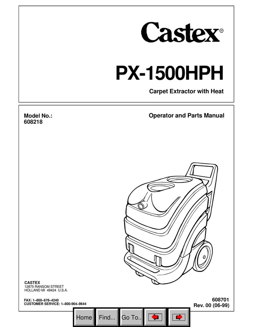
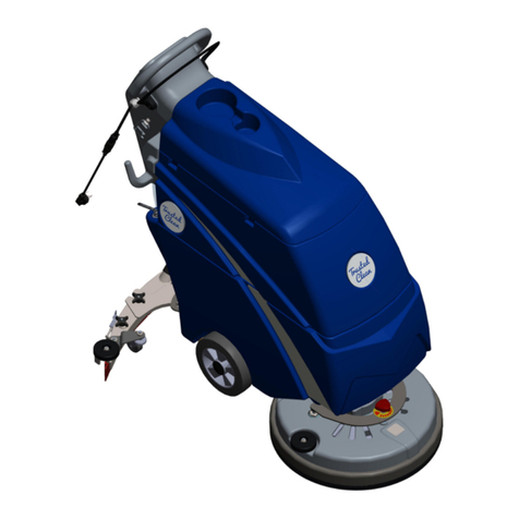
Castex PX-1500LP Product manual

Portable Carpet Extractor
Extractor Portátil Para Alfombras
608050
Rev. 00 (07Ć99
Model:
607779 - PXĆ1500LP
607780 - PXĆ1500LP PAC
PXĆ1500LP
Operator and Parts Manual
Manual de Operación y de Piezas
616-786–2330
FAX: 1–800–678–4240
CUSTOMER SERVICE: 1–800-964–9644
CASTEX
12875 RANSOM STREET
HOLLAND MI 49424 U.S.A.
Home
Find...
Go To..

OPERATION
2PX-1500LP (07–99)
This manual is furnished with each new model. It
provides necessary operation and maintenance
instructions.
Read this manual completely and understand the
machine before operating or servicing it.
This machine will provide excellent service. However,
the best results will be obtained at minimum costs if:
SThe machine is operated with reasonable care.
SThe machine is maintained regularly - per the
maintenance instructions provided.
SThe machine is maintained with manufacturer’s
supplied or equivalent parts.
MACHINE DATA
ModelNo.-
Install. Date -
Serial No.-
Please fill out at time of installation for future reference.
E1999 Tennant Company Printed in U.S.A.
TABLE OF CONTENTS
SAFETY PRECAUTIONS 3. . . . . . . . . . . . . . . . .
MACHINE SETUP 4. . . . . . . . . . . . . . . . . . . . . . . .
OPERATING FLOOR TOOL 4. . . . . . . . . . . . . .
UPHOLSTERY CLEANING 5. . . . . . . . . . . . . . .
DRAINING RECOVERY TANK 6. . . . . . . . . . . .
MAINTENANCE 6. . . . . . . . . . . . . . . . . . . . . . . . . .
STORING MACHINE 7. . . . . . . . . . . . . . . . . . . . .
TROUBLE SHOOTING GUIDE 8. . . . . . . . . . .
WIRING DIAGRAM 15. . . . . . . . . . . . . . . . . . . . . .
PARTS LIST 16. . . . . . . . . . . . . . . . . . . . . . . . . . . .
Home
Find...
Go To..

OPERATION
PX-1500LP (11–99) 3
SAFETY PRECAUTIONS
The following safety alert symbols are used throughout
this manual as indicated in their description.
WARNING: To warn of hazards or unsafe
practices which could result in severe personal
injury or death.
FOR SAFETY: To identify actions which must be
followed for safe operation of equipment.
The following information signals potentially dangerous
conditions to the operator or equipment:
FOR SAFETY:
1. Do not operate machine:
–Unless trained and authorized.
–Unless operator manual is read and
understood.
–In flammable or explosive areas unless
designed for use in those areas.
–With damaged cord or plug.
–If not in proper operating condition.
–In outdoor areas.
–In standing water.
–With the use of additional extension cords.
Only use manufacturer’s extension cord
equipped with machine which has proper
capacity and is grounded.
2. Before operating machine:
–Make sure all safety devices are in place
and operate properly.
3. When using machine:
–Do not run machine over cord.
–Do not pull machine by plug or cord.
–Do not pull cord around sharp edges or
corners.
–Do not unplug by pulling on cord.
–Do not stretch cord.
–Do not handle plug with wet hands.
–Keep cord away from heated surfaces.
–Report machine damage or faulty
operation immediately.
–Follow mixing and handling instructions
on chemical containers.
4. Before leaving or servicing machine:
–Turn off machine.
–Unplug cord from wall outlet.
5. When servicing machine:
–Unplug cord from wall outlet.
–Avoid moving parts. Do not wear loose
jackets, shirts, or sleeves.
–Use manufacturer supplied or approved
replacement parts.
WARNING: Hazardous Voltage. Shock or
electrocution can result. Always unplug machine
before servicing.
WARNING: Flammable materials can cause
an explosion or fire. Do not use flammable
materials in tank(s).
WARNING: Flammable materials or reactive
metals can cause an explosion or fire. Do not pick
up.
GROUNDING INSTRUCTIONS
Machine must be grounded. If it should
malfunction or breakdown, grounding provides a
path of least resistance for electrical current to
reduce the risk of electrical shock. This machine
is equipped with a cord having an
equipment–grounding conductor and grounding
plug. The plug must be plugged into an
appropriate outlet that is properly installed in
accordance with all local codes and ordinances.
Do not remove ground pin; if missing, replace
plug before use.
GROUNDED OUTLET
(3 HOLE)
GROUNDING PIN
Home
Find...
Go To..

OPERATION
4PX-1500LP (11–99)
MACHINE SETUP
1. Unscrew and remove front clear lid. Fill clean
water bladder with 57 L (15 gal) of hot water, 60°C
(140°F ) max. Add recommended cleaning agent
to proper dilution ratio (Figure 1.).
FIG. 1.
FOR SAFETY: When using machine, follow
mixing and handling instructions on chemical
containers.
WARNING: Flammable materials can cause
an explosion or fire. Do not use flammable
materials in tank(s).
NOTE: After filling clean water bladder, REPLACE
CLEAR LID AND TIGHTEN SECURELY. Suction in
recovery tank will overexpand clean water bladder if
cover is not sealed.
ATTENTION: Do not mix powdered chemicals in
extractor’s clean water bladder. Mix powdered
chemicals thoroughly in a bucket before pouring
into machine. Powders are unlikely to dissolve
completely and can clog solution pump system.
NOTE: If using a bucket to fill and empty machine use
separate buckets. Always use a clean bucket to fill
machine. Dirty water in clean water bladder will clog
solution pump system.
2. Connect 7.6 m (25 ft) extension power cord to
machine and plug into wall outlet (Figure 2.).
Grounded
Grounding
Edge/hole
Grounded
3 Hole Outlet
Ground Pin
(120V) (230V)
Outlet
FIG. 2.
FOR SAFETY: Do not operate machine with the
use of additional extension cords. Only use
manufacturer’s extension cord equipped with
machine which has proper capacity and is
grounded.
3. Attach vacuum and solution hoses to hose
connectors at front of machine and to the floor tool
(Figure 3.).
FIG. 3.
OPERATING FLOOR TOOL
NOTE: Vacuum carpet before cleaning.
1. Activate “VACUUM”and “PUMP”switches.
2. Place floor tool so bottom of floor tool is parallel to
floor. Squeeze trigger and apply downward
pressure on floor tool head and slowly pull tool
backwards using both hands. Release trigger
150 mm (6 in) from end of stroke (Figure 4.).
WARNING: Flammable materials or reactive
metals can cause an explosion or fire. Do not pick
up.
Home
Find...
Go To..

OPERATION
PX-1500LP (07–99) 5
FIG. 4.
3. Push floor tool forward over same path with trigger
released when returning for next stroke. Continue
this pull and push method with a slight overlap of
each stroke.
NOTE: For heavily soiled areas, repeat stroke or
change angle of stroke.
ATTENTION: Do not allow water or foam to enter
vacuum screen. Ball float will not stop foam
intake and vacuum motor damage will result (not
covered by warranty). If foam develops, remove
rear clear lid and pour 29.6 ml (1 oz.) of anti–foam
solution into recovery tank.
4. When finished cleaning, turn off switches and
drain recovery tank (See DRAINING RECOVERY
TANK).
5. Disconnect solution and vacuum hoses from
machine and neatly coil hoses for storing.
ATTENTION: Relieve water pressure from tool
before disconnecting hose. Squeeze trigger for
five seconds after turning off machine.
UPHOLSTERY CLEANING
This unit cleans most synthetic upholsery very well.
Extraction is not recommended for most cottons, silks
wools or natural fiber velvets. Check the cleaning
instructions sewn in the furniture by the manufacturer
for further instructions. Extra caution should be taken
with furniture that has been reupholstered. Any
material under the new upholstery may bleed and
discolor the new fabric.
1. Vacuum the upholstery before cleaning.
2. Test the fabric for color fastness. Pour a small
amount of cleaning solution on a white cloth. Hold
the damp portion of the cloth against an area of
upholstery which is hidden from view. Hold it there
for 60 seconds. If no color transfers to the cloth, it
should be safe to clean. However, always use
your best judgement.
3. Attach the vacuum and solution hoses to the front
of the extractor and to the accessory tool.
4. Activate the vacuum and pump switches.
5. Hold tool 150–200 mm (6–8 inches) above fabric
and squeeze trigger to spray cleaning solution
(Figure 5.).
FIG. 5.
6. Place tool on fabric and slowly pull tool
backwards.
7. When finished cleaning, turn off switches and
drain recovery tank (See DRAINING RECOVERY
TANK).
ATTENTION: Relieve water pressure from tool
before disconnecting hose. Squeeze trigger for
five seconds after turning off machine.
8. After you have relieved pressure in the solution
hoses as directed above, disconnect the solution
and vacuum hoses.
WARNING: Flammable materials or reactive
metals can cause an explosion or fire. Do not pick
up.
Home
Find...
Go To..

OPERATION
6PX-1500LP (11–99)
DRAINING RECOVERY TANK
NOTE: When clean water bladder is empty, recovery
tank MUST be emptied.
FOR SAFETY: When servicing machine,
disconnect cord from wall outlet.
1. Turn all switches off.
2. Remove drain hose from holder, position hose
over floor drain and twist off knob to drain
(Figure 6.).
FIG. 6.
NOTE: If using a bucket to drain machine, do not use
same bucket for filling clean water bladder!
3. Replace knob tightly before cleaning again.
4. After final draining, remove rear clear lid and rinse
both tank and shutoff float screen thoroughly to
prevent odor buildup.
DRAINING SOLUTION TANK
1 . To drain remaining solution from solution tank.
Disconnect solution hose and attach bleeder hose
(bleeder hose supplied with machine).
2. Activate “PUMP”switch. Pump solution into a
empty bucket (Figure 7.).
ATTENTION: Before disconnecting solution hose
and replacing with bleeder hose, relieve water
pressure from tool before disconnecting hose.
Squeeze trigger for five seconds after turning off
switches.
FIG. 7.
3. Rinse solution tank with clean water to prevent
odor build up. Run vacuum motor for 30 seconds
to discharge any moisture. Store extractor with
covers off to promote air circulation.
MAINTENANCE
To keep machine in good working condition, simply
follow machines daily, weekly and monthly
maintenance procedures.
WARNING: Hazardous Voltage. Shock or
electrocution can result. Always unplug machine
before servicing.
For ease of servicing, machine tank is hinged to pivot
away from chassis to allow access to inner
components. Make sure tanks are empty before
opening. To open extractor for servicing, follow these
steps:
a. Unplug extractor.
b. Unlatch front two latches.
c. Lift tank upward, away from chassis
(Figure 8.).
FIG. 8.
Home
Find...
Go To..

OPERATION
PX-1500LP (11–99) 7
DAILY MAINTENANCE:
1. Clean machine with a nonabrasive, nonsolvent
cleaner.
2. Rinse tanks out thoroughly.
3. Remove any lint buildup from shutoff float screen
(Figure 9.).
FIG. 9.
4. Remove and rinse recovery tank screen.
5. Check power cord for damage –replace if
necessary. Coil cord neatly after each use.
6. Remove any lodged debris from floor tool (Use a
coat hanger).
7. Check spray pattern for clogged spray tips.
WEEKLY MAINTENANCE:
1. Remove and soak spray tips in a tannin solution.
NOTE: Do not use pins, paper clips, etc. to unplug
spray tips. This will damage spray tips.
2. Flush pump system: Use acetic acid solution to
dissolve normal alkaline chemical buildup. Follow
these steps:
FOR SAFETY: When using machine, follow
mixing and handling instructions on chemical
containers.
a. Mix 473 ml. (16 oz) of acetic acid solution in
clean water bladder with7.5 L (2 gal) of hot
water, 60°C (140°F) maximum.
b. Place a bucket under spray jets to catch
spray.
c. Turn on “PUMP”switch.
d. Squeeze trigger on tool for 30 seconds.
e. Allow solution to remain in system for up to 6
hours in above freezing temperatures.
f. Later, spray out acetic acid solution into a
drain. Then run 11 L (3 gal) of clean water
through system to flush out impurities.
3. Inspect vacuum hose for holes and loose cuffs.
MONTHLY MAINTENANCE
1. Inspect cord grip for damage. Replace if
damaged. Neatly coil cord after each use.
2. Inspect tank for cracks.
3. Lubricate casters with a water resistance grease.
EVERY 250 HOURS OF OPERATION
Check vacuum motor for carbon brush wear.
Replace brushes when worn to a length of 10 mm
(0.38 in) or less.
STORING MACHINE
Store extractor with clear lids off to promote air
circulation.
ATTENTION: Do not expose to rain. Store
indoors.
ATTENTION: DO NOT ALLOW MACHINE TO
FREEZE WITH WATER IN PUMP SYSTEM. This can
crack internal parts and cause damage, which is not
covered by warranty. To avoid damage, run pump dry
before exposing the machine to freezing temperatures.
STORING MACHINE IN FREEZING
TEMPERATURES:
1. Drain tanks thoroughly.
2. Pour 1 L (32 oz) undiluted antifreeze into water
bladder.
3. Place a bucket under spray jets to catch spray.
4. Turn on “PUMP”switch.
5. Squeeze trigger on tool for 30 seconds.
6. Allow antifreeze to remain in system.
Home
Find...
Go To..

OPERATION
8PX-1500LP (10–97)
TROUBLE SHOOTING GUIDE
PROBLEM CAUSE SOLUTION
Uneven or no spray from tips. Dirty or plugged spray tips. Clean or replace tips.
Improper tip size or improper spray
angle. Replace with proper tips. Also check
alignment of spray tips. Spray tips
should overlap one another.
Worn spray tips. Replace spray tips.
Pump switch off. Turn the pump switch on.
Solution hose not connected. Make sure solution hose is connected.
Solution pump will not run. Fuse blown or circuit breaker tripped
in building. Replace fuse or reset breaker.
Faulty pump switch. Replace faulty switch.
Loose wiring to solution pump. Consult wiring diagram to repair wire.
Faulty solution pump motor. Repair or replace solution pump.
Poor or no vacuum suction. Fuse blown or circuit breaker tripped
in building. Find out if other appliances are
plugged into the same circuit.
Replace fuse or reset breaker. Plug
extractor into a less heavily loaded
circuit.
Faulty vacuum switch. Replace faulty switch.
Drain hose plug open or loose. Insert plug on drain hose.
Lint is clogging float shutoff screen. Remove recovery lid and clean lint off
screen.
Air is leaking around cover. Tighten recovery and solution tank
lids.
The vacuum hose is loose. Push hose firmly onto recovery tool
and onto front of extractor.
Holes in vacuum hose or loose hose
cuffs. Replace hose or thread cuffs securely
onto hose.
Faulty vacuum motor. Replace vacuum motor.
Float shutoff activated. Turn off vacuum, empty tank.
Faulty vacuum gasket. Check vacuum motor gasket.
Home
Find...
Go To..

OPERACIÓN
PX-1500LP (07–99) 9
Este manual se entrega con todas las unidades
nuevas. Incluye las instrucciones necesarias para el
uso y el mantenimiento de la unidad, además de la
lista de piezas. Lea este manual por completo y
comprenda el funcionamiento de la máquina
antes de usarla o de darle servicio.
Esta máquina le daráexcelente servicio. Sin embargo,
puede obtener los mejores resultados al costo mínimo
si:
SUsa la máquina con cuidado razonable.
SLe da mantenimiento a la máquina en forma regular,
de acuerdo a las instrucciones de mantenimiento
que incluimos.
SLa máquina recibe mantenimiento con las piezas de
repuesto del fabricante o equivalentes.
DATOS DE LA MÁQUINA
ModeloNo.:
Fecha de preparación:
No. de serie:
Sírvase llenar los datos en el momento de la preparación para
referencia en el futuro.
CONTENIDO
PREPARACIÓN DE LA MÁQUINA 9. . . . . . . .
PARA USAR EL ACCESORIO PARA
PISOS 10. . . . . . . . . . . . . . . . . . . . . . . . . . . . . . . . . .
PARA LIMPIAR TAPICERÍA11. . . . . . . . . . . . .
PARA VACIAR EL TANQUE DE
RECUPERACIÓN11. . . . . . . . . . . . . . . . . . . . . . .
MANTENIMIENTO 12. . . . . . . . . . . . . . . . . . . . . .
PARA ALMACENAR LA MÁQUINA 13. . . . .
GUIÁPARA RESOLVER PROBLEMAS 14.
DIAGRAMA DE CABLEADO 15. . . . . . . . . . . .
LISTA DE PIEZAS 16. . . . . . . . . . . . . . . . . . . . . .
ACCESORIOS OPCIONALES 20. . . . . . . . . . .
ATENCIÓN: Todos los operadores y el personal de
mantenimiento DEBEN leer y comprender este
manual antes de usar o dar mantenimiento a este
equipo. Para obtener ayuda póngase en contacto
con su centro local de servicio.
PREPARACIÓN DE LA MÁQUINA
1. Destornille y saque la cubierta delantera
transparente. Llene el depósito de agua limpia con
56.7 litros (15 gal) de agua caliente (60°C, 140°F).
Agregue algún producto limpiador recomendado a
la dilución apropiada (Figura 1.).
FIG.1.
ADVERTENCIA: Sólo use productos
químicos comerciales no inflamables, diseñados
especialmente para este tipo de equipo.
NOTA: Cuando haya llenado el depósito de agua
limpia, VUELVA A COLOCAR LA CUBIERTA
TRANSPARENTE Y SUJÉTELA CON FIRMEZA. La
succión en el tanque de recuperación dilatará
excesivamente el depósito de agua limpia si la
cubierta no sella por completo.
ATENCIÓN: No mezcle productos químicos en el
depósito de agua limpia del extractor. Mezcle
completamente los productos qumicos en polvo
en un recipiente por separado antes de vaciarlos
en la máquina. Es posible que los productos
químicos en polvo no se disuelvan por completo
y que puedan llegar a tapar el sistema de bombeo
de la solución.
NOTA: Use distintos recipientes para llenar y vaciar el
extractor. Siempre use un recipiente limpio para llenar
la máquina. Si se agrega agua sucia al depósito de
agua limpia se tapa el sistema de bombeo.
2. Conecte el cable de extensión de 7.6 m (25 pies)
a un tomacorriente con conexión a tierra
(Figura 2.).
Home
Find...
Go To..

OPERACIÓN
10 PX-1500LP (07–99)
PARA LA SEGURIDAD: Sólo conecte a un
tomacorriente con conexión a tierra. No use
adaptadores eléctricos ni elimine la patilla de
conexión a tierra en el enchufe macho. No use si
el cable estádañado.
Enchufe con toma
Masa borde/orificio
Toma de corriente
Patilla de conexion a tierra
(120V (230V
de tierra
FIG. 2.
3. Conecte las mangueras de aspiración y de
solución a los conectores de mangueras en la
parte delantera de la máquina y al accesorio para
pisos (Figura 3.).
FIG. 3.
PARA USAR EL ACCESORIO PARA PISOS
POR SU SEGURIDAD:
SNo use este aparato donde haya vapores o
polvos explosivos en el aire.
SNo recoja líquidos inflamables.
SDesconecte la corriente si se aleja de la
máquina.
NOTA: Aspire la alfombra antes de limpiarla.
1. Encienda los interruptores de aspiración
(VACUUM) y de la bomba (PUMP).
2. Coloque el accesorio para pisos de tal forma que
quede paralelo al piso. Apriete el disparador,
empuje hacia abajo el accesorio para pisos y
deslícelo lentamente hacia atrás con ambas
manos. Suelte el disparador 15 cm (6 plg) antes
de terminar cada pasada (Figura 4.).
FIG. 4.
3. Empuje el accesorio para pisos hacia adelante
sobre la misma área que acaba de cubrir, sin
apretar el disparador, hasta llegar al punto en que
deba comenzar la siguiente pasada. Continúe con
este método de deslizar hacia atrás y empujar
hacia adelante, superponiendo un poco cada
pasada a la anterior.
NOTA: En áreas sumamente sucias, repita las
pasadas o cambie el ángulo de las pasadas.
ATENCIÓN: No permita que el agua o la espuma
entren en la malla de aspiración. El flotador de
cierre no puede detener la entrada de espuma y se
daña el motor de aspiración (lo que no está
cubierto por la garantía). Si nota que se está
formando espuma, quite la cubierta transparente y
agregue 29.6 ml (1 oz) de solución antiespumante
en el tanque de recuperación.
4. Cuando haya terminado de limpiar, apague los
interruptores y vacíe el tanque de recuperación.
(Consulte PARA VACIAR EL TANQUE DE
RECUPERACIÓN.)
5. Desconecte las mangueras de solución y de
aspiración de la máquina y enrolle con cuidado las
mangueras para almacenarlas.
ATENCIÓN: Libere la presión de agua del
accesorio antes de desconectar la manguera.
Oprima el disparador durante cinco segundos
después de haber apagado los interruptores.
Home
Find...
Go To..

OPERACIÓN
PX-1500LP (10–97) 11
PARA LIMPIAR TAPICERÍA
Esta unidad limpia muy bien la mayoría de la tapicería
sintética. No se recomienda usar el método de
extracción en la mayoría de los algodones, las lanas
ni los terciopelos de fibras naturales. Obtenga más
instrucciones en las instrucciones de limpieza en las
etiquetas de los muebles. Debe tener mayor
precaución en muebles que hayan sido retapizados.
Es posible que el material que quedóabajo de la
nueva tapicería se decolore y manche la nueva
tapicería.
1. Aspire la tapicería antes de limpiarla.
2. Revise la firmeza de los colores. Vace una
pequeña cantidad de solución de limpieza en una
tela blanca. Sostenga durante 60 segundos la
parte húmeda de la tela contra alguna área oculta
de tapicería. Si no se transfiere nada de color a la
tela blanca, puede limpiar sin peligro. Sin
embargo, siempre use su juicio.
3. Conecte las mangueras de aspiración y de
solución a la parte delantera del extractor y al
accesorio.
4. Encienda los interruptores de aspiración y de la
bomba.
5. Sostenga el accesorio entre 15 y 20 cm (6 y 8 plg)
sobre la tela y oprima el disparador para rociar
solución de limpieza (Figura 5.).
FIG. 5.
6. Coloque el accesorio sobre la tela y lentamente
deslícelo hacia atrás.
7. Al terminar de limpiar, apague los interruptores y
vacíe el tanque de recuperación. (Consulte PARA
VACIAR EL TANQUE DE RECUPERACIÓN.)
ATENCIÓN: La manguera de solución contiene
solución de limpieza a presión que puede salir
disparada al desconectar la manguera. Libere esta
presión antes de desconectar la manguera
oprimiendo el disparador del accesorio de mano
durante cinco segundos despuésde apagar el
INTERRUPTOR DE ENCENDIDO DE LA BOMBA.
8. Después de que haya liberado la presión en la
manguera de solución como se indica
anteriormente, desconecte las mangueras de
solución y de aspiración.
PARA VACIAR EL TANQUE DE
RECUPERACIÓN
NOTA: Cuando el depósito de agua limpia estávacío,
DEBE vaciar el tanque de recuperación.
PARA LA SEGURIDAD: Desconecte el cable de
corriente antes de vaciar el tanque de
recuperación.
1. Apague todos los interruptores.
2. Quite la manguera de descarga de su soporte,
coloque la manguera sobre el desagüe y
destornille el tapón roscado para vaciar la solución
(Figura 6.).
FIG. 6.
NOTA: Si usa un recipiente para vaciar la máquina,
¡no use el mismo recipiente para llenar el depósito de
agua limpia!
3. Vuelva a colocar el tapón roscado y apriételo con
firmeza antes de volver a limpiar.
4. Cuando vacíe el tanque de recuperación por
última vez, quite la cubierta transparente posterior
y enjuague completamente tanto el tanque como
la malla del flotador de cierre para evitar malos
olores.
Home
Find...
Go To..

OPERACIÓN
12 PX-1500LP (10–97)
PARA VACIAR EL TANQUE DE SOLUCIÓN
1. Para vaciar el resto de la solución del tanque de
solución, desconecte la manguera de solución y
conecte la manguera de purga (la manguera de
purga se entrega junto con la máquina).
2. Encienda el interruptor de la bomba (PUMP).
Bombee la solución a un recipiente vacío
(Figura 7.).
ATENCIÓN: Antes de desconectar la manguera de
solución y reemplazarla por la manguera de
purga, libere la presión de agua del accesorio
antes de desconectar la manguera. Oprima el
disparador durante cinco segundos despuésde
apagar los interruptores.
FIG. 7.
3. Enjuague el tanque de solución con agua limpia
para evitar la acumulación de malos olores. Dje
funcionar el motor de aspiración durante 30
segundos para dejar salir toda humedad.
almacene el extractor sin las cubiertas para
permitir que circule el aire.
MANTENIMIENTO
ADVERTENCIA: Para evitar serias lesiones
personales: Desconecte la corriente eléctrica
antes de darle servicio a la unidad. Las
reparaciones deben ser realizadas por personal
autorizado.
Para mantener la máquina en buenas condiciones de
servicio, simplemente cumpla con los procedimientos
de mantenimiento diario, semanal y mensual.
Para facilitar el servicio, el tanque del extractor tiene
bisagras para abrirlo pivoteándolo hacia fuera y dejar
libre el acceso a los componentes internos. Para abrir
el extractor para darle servicio, haga lo siguiente:
a. Desconecte el extractor.
b. Abra los dos pestillos delanteros.
c. Levante la parte delantera del tanque hacia
arriba, separándolo del chasis (Figura 8.).
FIG. 8.
MANTENIMIENTO DIARIO:
1. Limpie la máquina con un limpiador no abrasivo,
no solvente.
2. Enjuague completamente los tanques.
3. Elimine cualquier acumulación de pelusa de la
malla del flotador de cierre (Figura 9.).
FIG. 9.
4. Saque y enjuague la malla del tanque de
recuperación.
5. Revise si el cable de corriente estádañado y
cámbielo si es necesario. Enrolle el cable con
cuidado después de cada uso.
6. Quite cualquier desperdicio que estéatorado en el
accesorio para pisos. (Use un gancho para ropa.)
7. Revise el rocío, para ver si hay la punta rociadora
estátapada.
MANTENIMIENTO SEMANAL:
1. Desmonte y remoje la punta rociadora en una
solución de tanino (ácido tánico).
NOTA: No use alfileres, horquillas, etc. para destapar
la punta rociadora ya que pueden la dañar.
Home
Find...
Go To..

OPERACIÓN
PX-1500LP (11–97) 13
2. Enjuague el sistema de bombeo: Use una
solución de cido acético para disolver la
acumulación normal de depósitos alcalinos. Haga
lo siguiente:
a. Mezcle 473 ml (16 oz) de una solución de
ácido acético en el tanque de agua limpia con
7.5 litros (2 galones) de agua caliente
(60°C,140°F, como máximo).
b. Sostenga un recipiente bajo la punta rociadora
para recoger la solución.
c. Encienda el interruptor de la bomba (PUMP).
d. Oprima el disparador en el accesorio durante
30 segundos.
e. Deje que la solución permanezca en el
sistema hasta 6 horas a una temperatura
superior a la temperatura de congelación.
f. Más tarde, rocíe la solución restante de ácido
acético en un desagüe o sumidero. Luego
deje correr 11 litros (tres galones) de agua
limpia a través del sistema para lavar las
impurezas.
3. Revise si la manguera de aspiración tiene orificios
o puños sueltos.
MANTENIMIENTO MENSUAL:
1. Revise si el enchufe macho del cable de corriente
estádañado. Cámbielo si es necesario. Enrolle
con cuidado el cable de corriente después de
cada uso.
2. Revise si el tanque estáagrietado.
3. Lubrique las rueditas orientables con grasa
resistente al agua.
CADA 250 HORAS DE USO:
Revise el motor de aspiración para determinar el
desgaste de las escobillas de carbón. Cambie las
escobillas cuando se hayan desgastado a 10 mm
(0.38 plg) o menos.
PARA ALMACENAR LA MÁQUINA
Almacene el extractor con las cubiertas transparentes
abiertas para que circule el aire.
ATENCIÓN: NO PERMITA QUE LA MÁQUINA SE
CONGELE CON AGUA DENTRO DEL SISTEMA.
Esta situación puede ocasionar grietas internas y
causar daños, lo que no estácubierto por la garantía.
Para evitar daños, haga funcionar la bomba en vacílo
antes de exponer la máquina a temperaturas menores
a la de congelación.
ALMACENAMIENTO DE LA MÁQUINA A
TEMPERATURAS MENORES A LA DE
CONGELACIÓN:
Asegúrese de que la máquina, la bomba y el sistema
de rocío estén completamente vacíos y secos.
Agregue anticongelante sin diluir en el depósito de
agua limpia y siga las instrucciones de vaciado del
sistema de bombeo en la página 13.
ATENCIÓN: No exponga la máquina a la lluvia.
Alamcénela bajo techo.
Home
Find...
Go To..

OPERACIÓN
14 PX-1500LP (10–97)
GUIÁPARA RESOLVER PROBLEMAS
PROBLEMA CAUSA SOLUCIÓN
La punta rociadora no rocía o el
rocío es diesigual. La punta rociadora estásucia o
tapada. Limpie o cambie la punta rociadora.
La punta rociadora es del tamaño. Camie a la punta rociadora apropiada.
Revise la alineación de la punta
rociadora de tal forma que rocíe en
línea recta.
La punta rociadora estádesgastada. Cambie la punta rociadora.
El interruptor de labomba (PUMP)
estáapagado. Coloque el interruptor de labomba
(PUMP) en la posición de encendido.
La manguera de solución no está
conectada. Asegúrese de que la manguera de
solucion estéconectada.
La bomba de solución no
funciona. El fusible estáquemado o el
sortacircuitos automático se abrióen
el edificio.
Cambie el fusible o restabelzca el
cortacircuitos automático.
El interruptor de la bomba está
defectuoso. Cambie el interruptor defectuoso.
El cableado al motor de la bomba está
defectuoso Consulte el diagrama de cableado y
repare los cables.
El motor de la bomba de solucion está
defectuoso. Repare o cambie la bomba de
solución.
No hay succión o es muy baja. El fusible estáquemado o el
sortacircuitos automático se abrióen
el edificio.
Revise si hay otros aparatos
conectados al mismo circuito. Cambie
el fusible o restablezca el
cortacircuitos. Conecte el extractor en
un circuitomenos ocupado.
El interruptor de aspiración está
defectuoso. Cambie el interruptor defectuoso.
El tapón de la manguera de descarga
estáabierto o suelto. Tape la manguera de descarga.
Hay pelusa tapando la malla del
flotador de cierre. Quite la cubierta del tanque de
recuperación y limpie la pelusa de la
malla.
El aire se estáfiltrando alrededor de
las cubiertas. Apriete las cubiertas del tanque de
recuperación y del tanque de solución.
La manguera de aspiración está
suelta. Empuje la manguera con firmeza
dentro del accesorio y dentro de la
parte delantera del extractor.
La manguera de aspiración tiene
orificios o los puños están sueltos. Cambie la manguera o atornillo los
puños con firmeza en la manguera.
El motor de aspiración está
defectuoso. Cambie el motor de aspiración.
El flotador de cierre se activo. Apague aparato y vacie el tanque.
El empaque, o junta obturadora, del
motor de aspiración estádefectuoso. Revise el empaque, o junta obturador,
del motor de aspiración.
Home
Find...
Go To..

WIRING DIAGRAMS
DIAGRAMA DE CABLEADO
PX-1500LP (09–97) 15
120V Wiring
ON
OFF
VACUUM PUMP
VACUUM
MOTOR
SOLUTION
PUMP
HANDLE CORD 14–4
TWIST LOCK
RECEPTACLE
GRN
BLK
WHT
BLK
RED
WHT
BLK
WHT
GRN
WHT BLK
GRN
BLK
BLK
RED
BLK
GRN
GRN
GRN
WHT
230V Wiring
BLK.
GRN.
TWISTLOCK
RECEPTACLE
WHT.
Home
Find...
Go To..

PARTS LIST
LISTA DE PIEZAS
PX-1500LP (10–97)
16
UPPER HOUSING PARTS
PIEZAS DE LA CAJA SUPERIOR
14
3
5
2
8
76
910 4
55
54
11 12 13
14
115
16
30
10
31 27
28
29
18
19
20
26
25
24
22
23 21
17
53
52
51
50
33
34
3536
40
41
32
56
39
37
38
44
43
42
47
49
48
44
45
46
Home
Find...
Go To..

PARTS LIST
LISTA DE PIEZAS
PX-1500LP (07–99) 17
UPPER HOUSING PARTS LIST
LISTA DE PIEZAS DE LA CAJA SUPERIOR
REF PART # DESCRIPTION QTY.
1. 140900 SCREW,10-24X3/4 7
2. 100103 ASM., LID 2
∇3. 100109 LID, OUTER RING 2
Y4. 10010 LID, CENTER CLEAR 2
Y. 140000 WASHER, FLAT 6
6. 101714 GASKET 1
7. 230187 NIPPLE 1
8. 602448 STANDPIPE 1
9. 180613 FLOAT, SHUTOFF 1
10. 140837 SCREW, #6-1/2 6
11. 130227 CORD, 14/4 X 20" (120V) 1
600324 CORD, POWER 2 X 1 M (230V) 1
12. 130166 CORD GRIP (120V) 1
130167 CORD GRIP (230V) 1
13. 19417 SWITCH 2
14. 140 19 NUT, KEP 3
1 . 140837 SCREW, 10-24X3/8 4
16. 230908.BK PLATE, REAR COVER 1
∇17. 19096 ASM., DRAIN HOSE 1
Y18. 140072 CLAMP 2
Y19. 140921 SLEEVE 1
Y20. 160627 HOSE, DRAIN 1
∇Y21. 701061 DRAIN HOSE STOPPER 1
Y22. 230831 KNOB 1
Y23. 230882 STRAP 1
Y24. 1400 6 WASHER, FENDER 1
Y2 . 1409 PLUG 1
26. 140307 CLAMP 1
27. 140231 SCREW, 3/8X1 1/2 4
28. 140017 WASHER, LOCK 4
29. 140028 WASHER, FLAT 4
30. 230696.BK BRACKET, DRAIN HOSE 1
31. 10128 HANDLE, BLUE 1
32. 1402 8 SCREW, STUD 3
33. 23084 PLATE, CORD CLAMP 1
34. 140834 SCREW, 1/4-20X /8 1
REF PART # DESCRIPTION QTY.
3 . 140 24 NUT, KEP 2
36. 230846 BRACKET, TANK SUPPORT 1
37. 140016 WASHER, LOCK 3
38. 140208 SCREW, 1/4-20X1 4
39. 6004 1 ASM., BLADDER PLATE 1
40. 60624 HOSE, 3/8 LP GRAY, 2.6' 1
41. 140310 CLAMP 2
42. 140000 WASHER, FLAT 4
43. 140016 WASHER, LOCK 7
44. 1402 9 SCREW, 1/4-20X /8 7
4 . 140016 WASHER, LOCK 3
46. 230946 BRACKET, TANK 1
47. 140932 LATCH, HOOD 2
48. 140801 SCREW, 8-32X3/8 8
49. 140023 WASHER, LOCK 8
0. 140713 RIVET, POP 1
1. 23090 TUBE, INLET 1
2. 101396 TANK, RECOVERY, BLUE 1
3. 602783 BLADDER 1
∇4. 100102 LID, CLEAR W/STD HOLE 1
Y. 600812 LID, OUTER RING 1
6. 180628 SCREEN, CLEAN WATER TANK 1
DECALS (NOT SHOWN)
LISTA DE CALCOMANÍAS (NO SE MUESTRAN)
N/S 120188 DECAL, DASH 1
N/S 120649 DECAL, WARNING EXTRACTOR..." 1
N/S 120906 DECAL, IMPORTANT DRAIN..." 1
N/S 120907 DECAL, IMPORTANT ALWAYS CLOSE..." 2
N/S 120190 DECAL, USE BLEEDER HOSE..." 1
N/S 120101 DECAL, CASTEX" 1
N/S 6080 1 DECAL, PXĆ1 00LP" 2
∇Assembly
YIncluded in Assembly
Home
Find...
Go To..

PARTS LIST
LISTA DE PIEZAS
PX-1500LP (10–97)
18
LOWER HOUSING PARTS
PIEZAS DE LA CAJA INFERIOR
5
4
3
2
1
6
7
8
910 11
12 13 7
14
13
15
40
18
13
15
17
16
23
22
21
20
20
24 25 26 19
29
30
31 32
28
31
32
32
37
39 383617
35 34
33
27
34
36
37
Home
Find...
Go To..

PARTS LIST
LISTA DE PIEZAS
PX-1500LP (07–99) 19
LOWER HOUSING PARTS LIST
LISTA DE PIEZAS DE LA CAJA INFERIOR
REF PART # DESCRIPTION QTY.
1. 210240 NUT, FLANGED 1
2. 100038 GASKET 1
3. 130996 MOTOR, VAC .7/3 STG (120V) 1
602741 -CARBON BRUSH (2/Pk) 2
130998 MOTOR, VAC .7/3 STG (230V) 1
190164 -CARBON BRUSH (2/Pk) 2
4. 140 01 NUT, LOCK 3
. 100118 GASKET 1
6. 230390 HINGE 1
7. 14088 SCREW, 1/4-20X1/2 9
8. 140804 SCREW, 10-24X1 1
9. 230907 AXLE 1
10. 140008 WASHER, FLAT 4
11. 103009 WHEEL 2
12. 140008 WASHER, FLAT 2
13. 140016 WASHER, LOCK 14
14. 230746 BRACKET, AXLE OFFSET 2
1 . 1402 9 SCREW, 1/4-20X /8 12
16. 140899 SCREW, 10-24X1 1/4 4
17. 140011 WASHER, FLAT 8
18. 10306 CASTER, SWIVEL 4" 2
19. 101092 CHASSIS, BLUE 1
REF PART # DESCRIPTION QTY.
20. 140831 SCREW, 6-32X /8 4
21. 130608 RECEPTACLE, TWIST LOCK (120V) 1
130609 RECEPTACLE, TWIST LOCK (230V) 1
22. 1 0933 PLUG, QUICK COUPLER 1
23. 1 061 NIPPLE 1
24. 140801 SCREW, 8-32X3/8 8
2 . 140023 WASHER, LOCK 8
26. 140932 LATCH, HOOD 2
27. 2867 NUT, NYLOCK 2
28. 1 0 11 HOSE BARB 1
29. 1 0406 ELBOW 1
30. 1400 8 WASHER, WAND 1
31. 160207 HOSE, 3/8" LP GRAY 1. ft
32. 140310 CLAMP 4
33. 130696 COVER, TWIST LOCK 1
34. 140308 CLAMP 2
3 . 160629 HOSE, 2"X24" 1
36. 140 19 NUT, KEP 3
37. 1 0412 ELBOW 2
38. 180108 PUMP, 100 PSI (120V) 1
180109 PUMP, 100 PSI (230V) 1
39. 160207 HOSE, 3/8" LP GRAY 1.8 ft
40. 130694 CORD, EXT 14/3X2 ' (120V) 1
PUMP PARTS LIST
LISTA DE PIEZAS DE LA BOMBA
2
3
4
6
1
5
REF PART # DESCRIPTION QTY.
∇1. 180103 PUMP, 100 PSI (COMPLETE) 1
Y2. 190129 KIT, PRESSURE SWITCH 1
190172 KIT, PRESSURE SWITCH (VITON) 1
190134 KIT, DIAPHRAGM ONLY 1
Y3. 190128 KIT, UPPER HOUSING 1
190124 KIT, CHECK VALVE ONLY 1
Y4. 190171 KIT, VALVE (VITON) 1
Y5. 190131 KIT, SERVICE 1
Y6. 190130 KIT, LOWER PUMP HOUSING 1
∇Assembly
YIncluded in Assembly
Home
Find...
Go To..

OPTIONAL ACCESSORIES
ACCESORIOS OPCIONALES
PX-1500LP (03–99)
20
HOSES
MANGUERAS
1
2
4
4
3
5
6
7
REF PART # DESCRIPTION QTY.
∇1. 16018 HOSE, SOLUTION 1 ' 1
160186 HOSE, SOLUTION 2 ' 1
Y2. 1 0913 COUPLER, QUICK SER. 60 1
Y3. 1 0933 PLUG, QUICK COUPLER 1
Y4. 1 061 NIPPLE 2
∇. 160400 HOSE, VACUUM 1 ' 1
160401 HOSE, VACUUM 2 ' 1
Y6. 160430 CUFF, HOSE 1-1/2" 2
7. 1604 1 CONNECTOR, VAC HOSE 1 1/2" 1
N/S 700141 BLEEDER HOSE 1
∇Assembly
YIncluded in Assembly
5”HAND TOOL
ACCESORIO DE MANO DE 12.7 CM
10
211 12 13
9
8
5
4
36
1
7
REF PART # DESCRIPTION QTY.
200 0 TOOL, HAND " (COMPLETE) 1
1. 200431.BK TOOL, HAND 1
2. 1 0913 COUPLER, QUICK, SER. 60 1
3. 1 061 NIPPLE, CLOSE 1
4. 20090 LEVER, K-VALVE W/PIN 1
. 210210 VALVE, FLOW CONTROL 1
6. 190600 VALVE PIN & SPRING (NOT SHOWN) 1
7. 210148 CAP, HEX, VALVE 1
8. 1 0606 NIPPLE, HEX 1/4" 1
9. 1 0403 ELBOW, ST 1/4" 4 °1
10. 200992 BODY, SPRAY 1/4"F 1
11. 200996 SCREEN, SPRAY BODY 1
12. 20096 TIP, BRASS #8002 1
13. 200994 CAP, SPRAY BODY 1
Home
Find...
Go To..
This manual suits for next models
3
Table of contents
Languages:
Other Castex Floor Machine manuals

Castex
Castex PX-1500HPH Product manual

Castex
Castex BR-2250 Product manual

Castex
Castex PX-1500LPH Product manual

Castex
Castex Power Eagle 700 User manual

Castex
Castex HS-1100 Product manual

Castex
Castex Power Eagle 350 PE1300 Programming manual

Castex
Castex Anser AN2030 Programming manual

Castex
Castex SCX-400 611458 Product manual

Castex
Castex falcon 1500 User manual

Castex
Castex BR-1600 Product manual