OPERATION
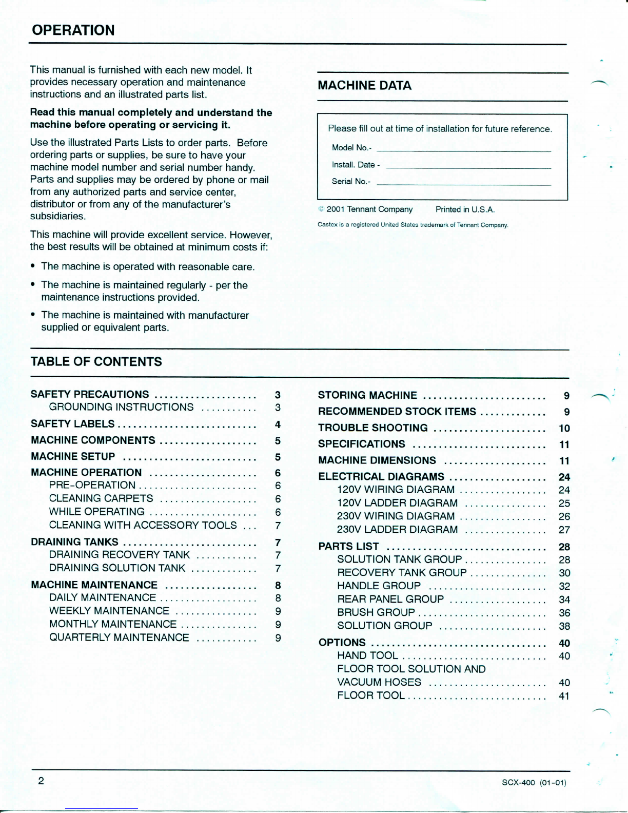
7.
Plug
machine's
powercordinto
a
groundedwall
outlet
(Figure
4).
Grounded
3
HoleOutletGroundedOutlet
Ground
Pin
Grounding
Edge/hole
V
(120V)
(230V/240V)
FIG.
4
FOR
SAFETY:
Donot
operatemachine
unless
cord
is
properlygrounded.
FOR
SAFETY:
Donot
operatemachinewith
the
useofan
extensioncord.
FIG.
6
3.
Releasetriggers
atendof
path
and
continue
to
pullmachine
to
pick
up
excess
solution.
4.
Tip
machineback
on
wheels
and
pushmachine
forward
to
beginnextpath.
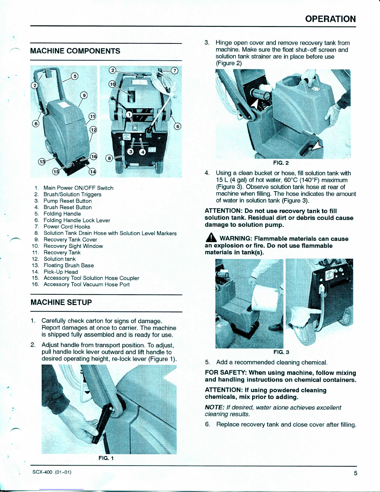
MACHINEOPERATION
FOR
SAFETY:
Donot
operatemachineunless
operator
manual
is
read
and
understood.
PRE-OPERATION
1.
Vacuumcarpet
and
removeotherdebris.
2.
PerformMACHINESETUPprocedures.
3.
Inspectpowercord
for
damage.
CLEANING
CARPETS
1.
Turnmainpowerswitch
on
(Figure
5).
2.
FIG.
5
To
begincleaningcarpets,pulltriggers
and
slowly
pullmachinebackwards(Figure
6).
WHILE
OPERATING
1.
Overlapeachpath
by50mm(2
in).
mm.
WARNING:Flammablematerials
or
reactive
metals
can
cause
an
explosion
or
fire.
Donot
pick
up.
2.
Workawayfromwalloutlet
and
powercord
to
preventcorddamage.
3.
Periodicallycheck
for
excessivefoambuildup
in
recovery
tank.
Usea
recommendedfoamcontrol
solution
to
preventvacuummotordamage.
ATTENTION:Excessive foambuildupwill
not
activate
the
floatshut-offscreen.
4.
If
brushstops,
the
circuit
breaker
may
havebeen
tripped.Unplugpowercord,checkbrush
for
obstruction.Pushbrushresetbutton
to
resume
(Figure?).
5.
6.
FIG.
7
To
cleanheavilysoiledareas,repeatcleaningpath
fromdifferentdirection.
Observerecoverysitewindow,whenrecovery
appears
to
stop,drainrecoverytank
(See
DRAININGTANKS).
SCX-400
(01-01)