CAVIDYNE Caviblaster 2040-ROV-M2 Manual

Operation &
Maintenance
Manual
Model 2040-ROV-M2
CAVIDYNE, LLC
5077 Fruitville Rd.; Ste 109-157
Sarasota, FL 34232
Phone (352) 275-5319
www.caviblaster.com

CAVIDYNE LLC is not responsible for damages or injuries
resulting from a failure to comply with instructions in this
manual. Please read and study the entire manual carefully
before use.
The CaviBlaster 2040-ROV-M2 must only be operated and
maintained by trained personnel.
This equipment generates high pressure water and is
intended for underwater use only. Serious personal injury
or death may result from improper use.
Page - 2
For more information please email [email protected] or call 1-(352)275-5319

TA LE OF CONTENTS
1.0 UNIT SPECIFICATIONS.............................................................................................5
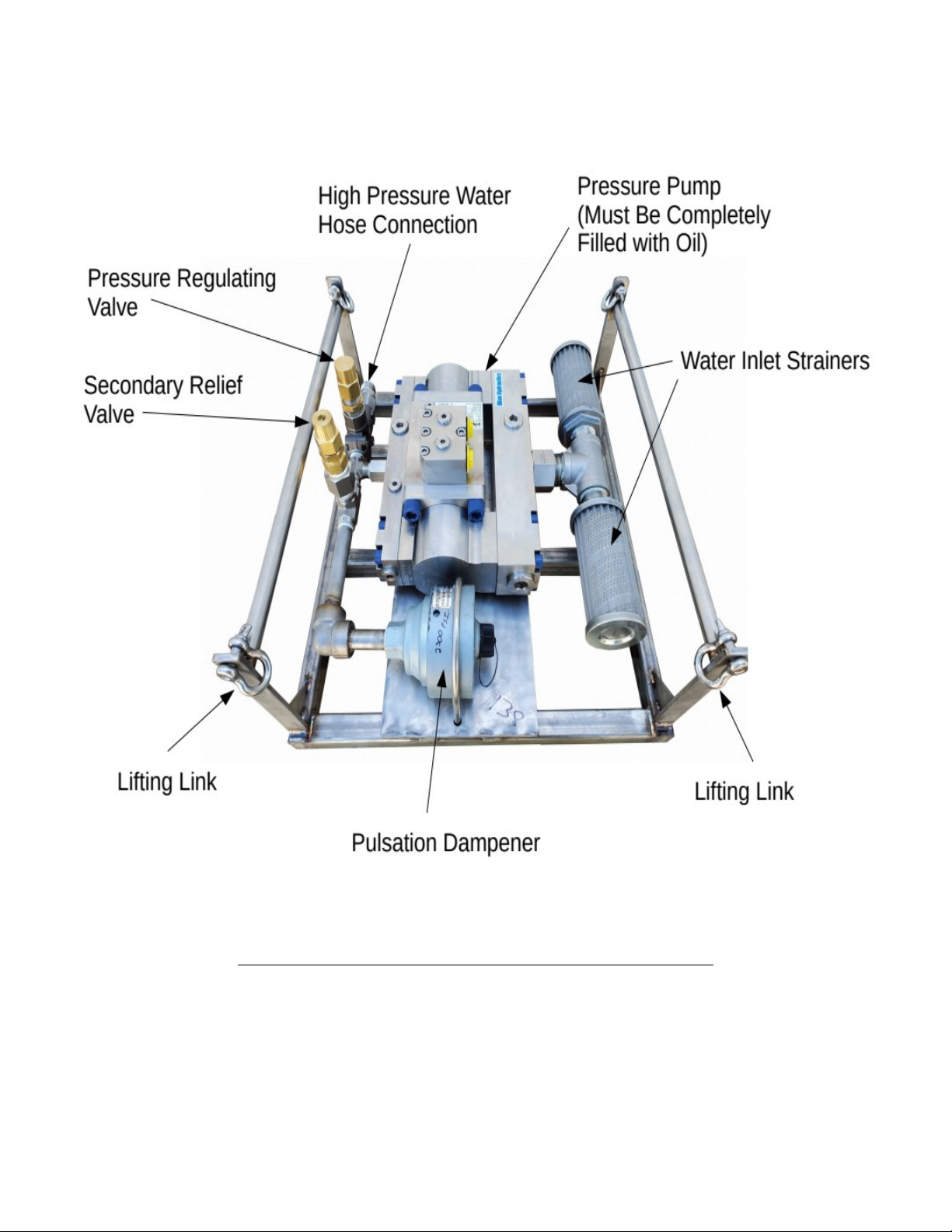
2.0 GENERAL DESCRIPTION..........................................................................................6
2.1 Using this Manual.....................................................................................................8
2.2 Conventions.............................................................................................................8
2.3 Scope.......................................................................................................................8
2.4 Terms and Abbreviations.........................................................................................8
3.0 SAFETY INFORMATION............................................................................................9
3.1 Personal Safety........................................................................................................9
3.2 Personal Protective Equipment..............................................................................10
3.3 Modification to the Equipment................................................................................11
4. 0 INSTALLATION........................................................................................................12
4.1 Uncrating and Lifting..............................................................................................12
4.3 Initial Set-Up...........................................................................................................13
5.0 OPERATION..............................................................................................................14
5.1 Preparing the CaviBlaster for Operation................................................................14
5.2 Startup of the CaviBlaster......................................................................................15
5.3 Normal Operation...................................................................................................15
5.4 Adjusting the CaviBlaster for Maximum Performance...........................................16
5.5 Recommendations for Effective Results................................................................19
6.0 MAINTENANCE........................................................................................................21
6.1 Basic Preventive Maintenance Recommendations...............................................22
6.3 Pump Service.........................................................................................................22
6.4 Inspection / Cleaning of Water Inlet Strainer.........................................................22
7.0 TROU LESHOOTING..............................................................................................23
8.0 REPLACEMENT PARTS..........................................................................................24
APPENDIX - COMPONENT LITERATURE....................................................................25
Page - 3
For more information please email [email protected] or call 1-(352)275-5319

LIST OF FIGURES & TA LES
Figure 1.1 – CaviBlaster 2040-ROV-M2 Specifications .. .. .7
Figure 2.1 – CaviBlaster 2040-ROV-M2 General Features .12
Figure 4.1 – Lifting Guidelines.........................................................................................18
Figure 5.2 – Lance Position for Best Cleaning results ... .. 19
This space intentionally left blank
Page - 4
For more information please email [email protected] or call 1-(352)275-5319

1.0 UNIT SPECIFICATIONS
The CaviBlaster 2040-ROV power unit consists of a 55HP (37 kW) Cross hydraulic gear
motor power-pack and a CAT 3560 triplex plunger pump. Detailed performance and
specifications are listed below:
Cavi laster 2040-ROV-M2 Specifications
Nominal Pump Flow 20 GPM (76 LPM)
Nozzle Operating Pressure 4,000-PSI (275 BAR)
Driver 50M052 Cross Hydraulic Gear Motor
Installation Environment Submersible
Hydraulic Oil Flow Requirements *See below.
Overall Unit Dimensions (L x W x H) 22” x 20” x 10” (55.8 cm x 50.8 cm x 25.4 cm)
Maximum Pressure Hose Length 300 LF (100 meters) of 3/4” (1.9 cm) diameter
Power Unit Weight (Dry) 273 LBS (124 KG)
*Hydraulic Power Unit must be capable of operating the water pressure pump at 1160 rpm and 55 HP.
Consult CaviDyne regarding the suitability of your existing Hydraulic Power Unit.
Figure 1.1 – CaviBlaster 2040-ROV-M2 Specifications
(EOS)
Page - 5
For more information please email [email protected] or call 1-(352)275-5319

2.0 GENERAL DESCRIPTION
The CaviBlaster 2040-ROV-M2 high-pressure water power unit allows the operator to
use the water flow and pressure to generate cavitation at the end of the proprietary
nozzle.
The CaviBlaster cleans the surface of any underwater structure using the energy
released by the implosion of the bubbles during the cavitation process. When directed
at the surface being cleaned, the energy released by the collapsing bubbles causes
marine growth to be removed from the surface.
The system consists of a portable high-pressure pumping unit designed for submersible
ROV use and a high pressure cavitation lance (connected to ROV manipulator) with
connecting high pressure hose.
The CaviBlaster 2040-ROV-M2 power unit is a complete “plug and play” system built on
a supporting platform that allows quick deployment and/or installation of the unit. Water
is supplied directly from the unit operating environment.
The unit is equipped with many features to maintain safety while operating at pressures
of 4,000-psi (275 bar).
Page - 6
For more information please email [email protected] or call 1-(352)275-5319
For more information on the CaviBlaster system please visit us at:
www.caviblaster.com

Figure 2. 2 – CaviBlaster 2040-ROV-M2 General Features
Page - 7
For more information please email [email protected] or call 1-(352)275-5319

2.1 Using this Manual
Every attempt has been made to ensure that this documentation is complete and
accurate at the time of publication. It is imperative; however, that anyone
attempting to use this manual must have good comprehension of how this
equipment operates. Further, this manual can in no way replace the common
sense of an individual. If at any time this manual seems to contradict itself, or
common sense, discontinue the procedure, re-read the section, and seek
assistance from CaviDyne or other personnel familiar with the operation of this
equipment.
2.2 Conventions
The first time a component is mentioned, it is typically followed by a figure
reference; e.g., Emergency Stop button (See Figure 2.1). Figure numbers and
section numbers are always coincident.
When other sections are referenced the SECTION NAME will appear in italic
caps. The electronic version allows users to click on the section name or figure
reference to jump to that section. The words “This space intentionally left
blank” will appear where there is more than 3 inches of white space.
(EOS) will appear above the page number on the last page of each section.
2.3 Scope
This manual covers installation, operation, and maintenance of the CaviBlaster
2040-ROV-M2. It is essential that personnel who will operate and/or service this
equipment familiarize themselves with this manual. Standard components, such
as the unit engine and pump, are covered by the manufacturer’s literature found
in the Appendix.
2.4 Terms and Abbreviations
CCW Counterclockwise
CW Clockwise
EOS End of Section
GPM Gallons Per Minute
HP Horsepower
LPM Liters Per Minute
PPE Personal Protective Equipment
PSI Pounds Per Square Inch (without suffix, assumed to be gauge pressure).
Page - 8
For more information please email [email protected] or call 1-(352)275-5319
(EOS)

3.0 SAFETY INFORMATION
The CaviBlaster 2040-ROV-M2 power unit is an inherently powerful and potentially
dangerous piece of equipment; however, with proper care and training it can be
operated safely. The 2040-ROV-M2 must only be operated by personnel that have read
and understand this manual. It is intended to reinforce and review safety techniques to
prevent personal injuries and property damage.
Users must comply with all local, state, and national laws concerning high-pressure
water jetting equipment as well as all underwater work regulations.
It is strongly recommended that this entire manual be reviewed in-depth before
operating or servicing this equipment. Service work should only be performed by
individuals who are proficient in using this equipment. Refer to the applicable section in
this manual for the correct procedures prior to any installation, setup, or maintenance
work.
Note that the oil pressure compensator is not a pressurized component and therefore
not a safety hazard. It is open at one end and connected to the pressure pump oil
chamber at the other end. Its purpose is simply to balance the oil pressure in the water
pressure pump with the unit’s surrounding environmental pressure to prevent damage
to the water pressure pump.
3.1 Personal Safety
Operation of the CaviBlaster 2040-ROV-M2 underwater submersible ROV-
mounted cleaning system must only be operated by personnel who have been
trained in its use. Operation of the system without the proper training can result in
property damage and damage to the CaviBlaster unit.
CaviDyne LLC is not responsible for damages resulting
from a failure to comply with instructions in this manual.
Please read carefully before use.
Page - 9
For more information please email [email protected] or call 1-(352)275-5319

If maintenance or repair of the CaviBlaster is being
conducted out of the water, remember that the unit
generates a high pressure water jet stream. Never
direct the jet stream at a person or animal. Never
direct the jet stream toward power lines or other
high voltage equipment.
Ensure that there is a safe area to work while
operating or maintaining the CaviBlaster 2040-ROV-
M2.
Seek immediate medical attention if the operator suffers an
injury as the result of contact with the high-pressure water
stream. Serious personal injury can result from an
untreated water injection wound.
3.2 Personal Protective Equipment
Always wear appropriate Personal Protective Equipment (PPE) when performing
maintenance or calibration on this equipment.
Personnel operating or working in the vicinity of the power unit should wear
appropriate hearing protection when operating the CaviBlaster during
maintenance or calibration procedures.
Personnel performing maintenance or calibration procedures on the CaviBlaster
2040-ROV-M2 system should always wear neoprene or heavy rubber gloves to
provide protection to the hands and, in particular, to the nails. The gloves will
absorb most of the energy produced by bursting cavitation bubbles and prevent
the cavitation bubbles from contacting the operators’ hands. The gloves will also
protect operators’ hands from the initial shockwave when the lance is activated.
Failure to wear appropriate PPE may result in personal
injury.
Page - 10
For more information please email [email protected] or call 1-(352)275-5319

3.3 Modification to the Equipment
Do not make any unauthorized modifications or repairs to this equipment.
Components used throughout this assembly were specifically designed or
selected to safely meet the unique high-pressure requirements. Only replace
parts with those recommended by or supplied by CaviDyne. Any unapproved
modifications will void the equipment warranty. Unauthorized modification or part
substitution can result in serious personal injury or property damage.
This space intentionally left blank
Page - 11
For more information please email [email protected] or call 1-(352)275-5319
Unauthorized replacement of any part may lead to
catastrophic equipment failure and serious personal
injury.
(EOS)

4. 0 INSTALLATION
The CaviBlaster 2040-ROV-M2 must be securely attached to the ROV using the
vibration mounts supplied or other secure fastening mechanism.
4.1 Uncrating and Lifting
Unpack the equipment and inspect for damage. If damage is found, immediately
contact CaviDyne and the shipping company. If the unit will not be installed
immediately, provide adequate indoor storage to protect against damage.
The CaviBlaster power unit should be lifted from underneath or via de Lifting
links. Do not use components of the Cavi laster to lift the entire unit.
Figure 4. 3 – Lifting Guidelines
Page - 12
For more information please email [email protected] or call 1-(352)275-5319

4.3 Initial Set-Up
After first receiving the CaviBlaster power unit, the following must be completed
See Figures 2.1 for item locations.
1. Add oil to pump by completely filling pump to top of fill port.
2. Install fill plug.
3. Stand unit on end with pump motor at top.
4. Remove oil pressure compensator fill port cap.
5. Fill oil pressure compensator and hose with oil.
6. Allow unit to sit for several minutes to vent any trapped air.
7. Top-off oil as required.
8. Replace oil pressure compensator fill port cap.
9. Set unit back down on vibration mounts.
10.It is important that there is no air trapped in the pump oil system.
11.Connect hydraulic power unit hoses.
12.Connect water pressure hose.
The CaviBlaster 2040-ROV-M2 can be used with seawater but must
be flushed and rinsed with fresh water after every use in seawater.
Failure to flush and rinse the power unit after use in seawater will
result in increased wear and tear on components and can cause the
pump valve(s) to stick in the open position. This will prevent the
system from producing the correct operating pressure.
(EOS)
Page - 13
For more information please email [email protected] or call 1-(352)275-5319
Pump fluids may have been removed for shipment.
Check ALL fluid levels prior to starting.

5.0 OPERATION
The Cavi laster 2040-ROV-M2 should only be operated
by properly trained personnel who are familiar with the
contents of the manual. Review the safety
requirements found in Section 3 before operating.
5.1 Preparing the Cavi laster for Operation
The following checklist should be completed in advance, so that the unit is
always ready for immediate use. This should be completed after each use.
1) Inspect the CaviBlaster power unit, hoses, JIC fittings and lance for any signs
of damage.
2) Inspect the water inlet strainer to ensure that it is not clogged (See Figure
2.1). Clean if necessary.
3) Check for proper pressure pump oil level (See pump Owner’s Manual found
in the Appendix). Add oil (SAE 30 non-detergent) if necessary. PUMP MUST
E COMPLETELY FILLED.
Incorrect oils should not be used as they may damage
the equipment.
Page - 14
For more information please email [email protected] or call 1-(352)275-5319

5.2 Startup of the Cavi laster
Before starting the CaviBlaster 2040-ROV-M2 unit, review all safety requirements
found in Section 3.0 SAFETY INFORMATION. This equipment should only be
operated by individuals who have read and understand the CaviBlaster
Operation and Maintenance Manual.
1) Verify that the unit has been properly prepared for operation as described
in Section 4.0 INSTALLATION.
2) Verify that the lance is properly connected to the CaviBlaster and the
ROV.
3) Run the ROV hydraulic system to verify that the CaviBlaster hydraulic
motor and pressure pump are functioning correctly.
5.3 Normal Operation
Normal operation of the CaviBlaster system is defined as user control of water
flow via the lance. In the absence of a diver, control of the power unit is
accomplished by the ROV manipulator. Should a problem develop with the
control valve, discontinue using the CaviBlaster until fixed.
Review the safety requirements for PPE and safe
operation before proceeding.
1) The ROV hydraulic system needs to be operating at a capacity that
matches the water pressure pump requirements for the CaviBlaster 2040-
ROV-M2 to function correctly. Unlike gasoline or diesel engines, a
hydraulic motor will run as fast as the oil supply it receives, which means
that the hydraulic oil supply must be adjusted to match the water pressure
pump requirements. Consult with CaviDyne to determine if your high
pressure oil supply unit is suitable for use with the CaviBlaster 2040-ROV-
M2.
Page - 15
For more information please email [email protected] or call 1-(352)275-5319

2) Activate the cleaning cavitation stream by turning ON the hydraulic power
unit.
Although the Cavi laster system is safe to use when submerged in
water, the system generates a high-pressure (up to 4,000-psi [275 bar])
water stream, which can cause injury when the lance is out of the water.
ALWAYS keep the lance submerged when the pressure pump is
engaged.
5.4 Adjusting the Cavi laster for Maximum Performance
The pressure at the nozzle of the lance has to be maintained within certain limits
to achieve cavitation and for best performance results. If using a calibration
pressure gauge situated between the pressure hose and the CaviBlaster lance,
the water pressure should be 4,000-psi (275 bar) with the lance submerged and
the hydraulic power unit operating. For best results, repeat this calibration
procedure if cleaning performance degrades, or every 3 months at a maximum.
To calibrate the pressure at the lance, follow the procedure below
- Stop the hydraulic power unit to discharge any residual pressure in the hose
lines.
- Disconnect the lance from the main hose line.
- Attach the calibration gauge between the main hose line and the lance and
tighten the JIC connections. (See Figure 5.1)
- Submerge the lance. Because of the danger of the operator coming in contact
the water stream from the cavitating nozzle, CaviDyne does NOT recommend
calibrating the lance out of the water. Use extra care to avoid the water
stream if doing so.
- Ensure that the cavitation nozzle is pointed away from the diver’s or
operator’s hands, arms and body.
- Start the hydraulic power unit.
- Hold the lance tight and observe the calibration gauge (See Figure 5.1).
Page - 16
For more information please email [email protected] or call 1-(352)275-5319
A CALI RATION GAUGE IS RECOMMENDED WITH EVERY
UNIT. CONNECT ETWEAN THE END OF THE HOSE AND
THE LANCE.

- Turn the knob on top of the pressure regulating valve until pressure reads
4,000-psi (275 bar) on the calibration gauge. Turning the knob clockwise will
increase the pressure and turning it counter clockwise will decrease the
pressure.
This space intentionally left blank
Page - 17
For more information please email [email protected] or call 1-(352)275-5319
DO NOT ADJUST THE PRESSURE AT THE LANCE TO MORE
THAN 4,000-PSI (275 AR). HIGHER PRESSURE WILL NOT
IMPROVE PEFORMANCE AND COULD RESULT IN SERIOUS
DAMAGE TO THE PUMP.
HOSES ARE RATED FOR 4,000-PSI (275 AR) PRESSURES
A OVE 4,000-PSI (275 AR) COULD RESULT IN HOSE
FAILURE.

Figure 5.1 – Lance Pressure Calibration
Page - 18
For more information please email [email protected] or call 1-(352)275-5319

5.5 Recommendations for Effective Results
When the ROV operator is ready to commence cleaning operations, verify that
the lance is securely attached to the manipulator.
Once the hydraulic power unit is operational and the water jet stream is flowing
from the lance, the ROV operator has to find the most effective distance between
the lance nozzle and the surface being cleaned. (See Figure 5.2)
1. Engage the ROV’s hydraulic power unit to activate the CaviBlaster unit.
2. The most efficient operating technique is to hold the nozzle 2-5 inches (5-12
cm) away from the surface to be cleaned and at a 25 to 45 degree angle to
the surface being cleaned (See Figure 5.2). The ROV operator needs to
observe the shape of the cavitating jet cone. At greater depths, the higher
ambient pressure will cause the jet cone to be shorter. The widest zone of the
cone is the most efficient part of the cavitating jet. Placing the nozzle closer
than 2 inches (5 cm) from the surface being cleaned will not allow for efficient
cavitation performance and will degrade the cleaning capability of the
CaviBlaster system.
3. Follow all safety regulations that may be applicable to the work being
performed.
Figure 5.2 – Lance Position for Best Cleaning Results
Page - 19
For more information please email [email protected] or call 1-(352)275-5319

5.6 Shutting Down the Cavi laster 2040-ROV-M2.
1. Shut down the ROV hydraulic power unit, this will turn off the pressure pump
and relieve pressure in the system.
2. It is now safe to remove the lance from the water.
3. Flush the system and rinse the power unit with fresh water at the end of the
day or work shift.
This space intentionally left blank
EOS
Page - 20
For more information please email [email protected] or call 1-(352)275-5319
Table of contents
Other CAVIDYNE Industrial Equipment manuals
Popular Industrial Equipment manuals by other brands

Kval
Kval 558 Operation manual

STEELTEC
STEELTEC XWS007 instruction manual

Festo
Festo DHPC operating instructions

FLENDER
FLENDER FASTEX IC130 Assembly and operating instructions

Honeywell
Honeywell Industrial HERMetic Sampler GTX Chem Operation and service manual

Emerson
Emerson FISHER T208 Series installation guide

ABB
ABB HT843234 Operation manual

Whitmore
Whitmore OilSafe Advanced Bulk System owner's manual

THORLABS
THORLABS IO-F-780APC user guide

Dustcontrol
Dustcontrol DC 4000 PCB Original instructions

ESAB
ESAB OPC Flux recovery unit instruction manual

Mitsubishi Electric
Mitsubishi Electric BC34 Installation, operation & maintenance manual