CB ELECTRONICS SR-3 User manual

CB ELECTRONICS
Loddonside, Lands End House, Beggars Hill Road, Charvil, Berks RG10 0UD, UK
Tel: +44 (0)118 9320345, Fax: +44 (0)118 9320346, www.colinbroad.com
SR-4/SR-24/SR-32/MR Custom/RM-6/Video Slave
Serial Remotes/Synchronizers
User Manual
* Multiple serial ports .............. SR-3: 3 Output, 1 Input; SR-4: 4 Output, SR-24A 5 Output
* Multiple serial ports ..............SR-24: 4 Output; SR-24A: 4 Output, 1 Output/Input, 1 Input
* Sony P2 protocol ................................ DAT’s, VTR’s, DA-88, FEG Prima ..
* P2 Plug and Play .......................... Sony P2 Auto recognition and Configuration
* ES BUS protocol ...................................Studer D820/D827, AK ES 1.11
* Studer TLS4000 protocol .............................. Studer Audio Tape Recorders
* Ampex Protocol .................................... VPR-3, VPR-80, Timeline Lynx
* 8(SR-3/4) or 24(SR-24) Record Ready keys .................... Upto48record Channels
* RS422 Input ..................... OnSR-3 and SR-24 for use with DAW or Video Editors
* Parallel In/Out ...................................6parallel inputs, 6 parallel outputs
* Parallel Remote with tallies (SR-24) ................................. SSLS29format
* Timecode Output ..............................Follows the master position and Offset
* Timecode Input .................................. Alloutputs will chase remote code
* Built in P2 Synchroniser ..................... Will synchronise any suitable 9-pin Machine
* Real or Virtual Master ...................... Perfect Machine as Master, Tapeless Master
* 11 (SR-3/4) or 15(SR-24) Macro Keys ............................. User configurable
The SR Series remote controls have been designed using experience gained from the MR series
remote control system. Designed as a stand-alone controller or to be used with Digital Audio Work-
stations the SR serial remotes make cost effective ergonomic solutions.
Although the user can control only one machine at a time from the remote both the record and un-
record commands are global so that multiple machines may be controlled simultaneously using the
internal 9-pin synchroniser or using the built in chase feature of modern machines.
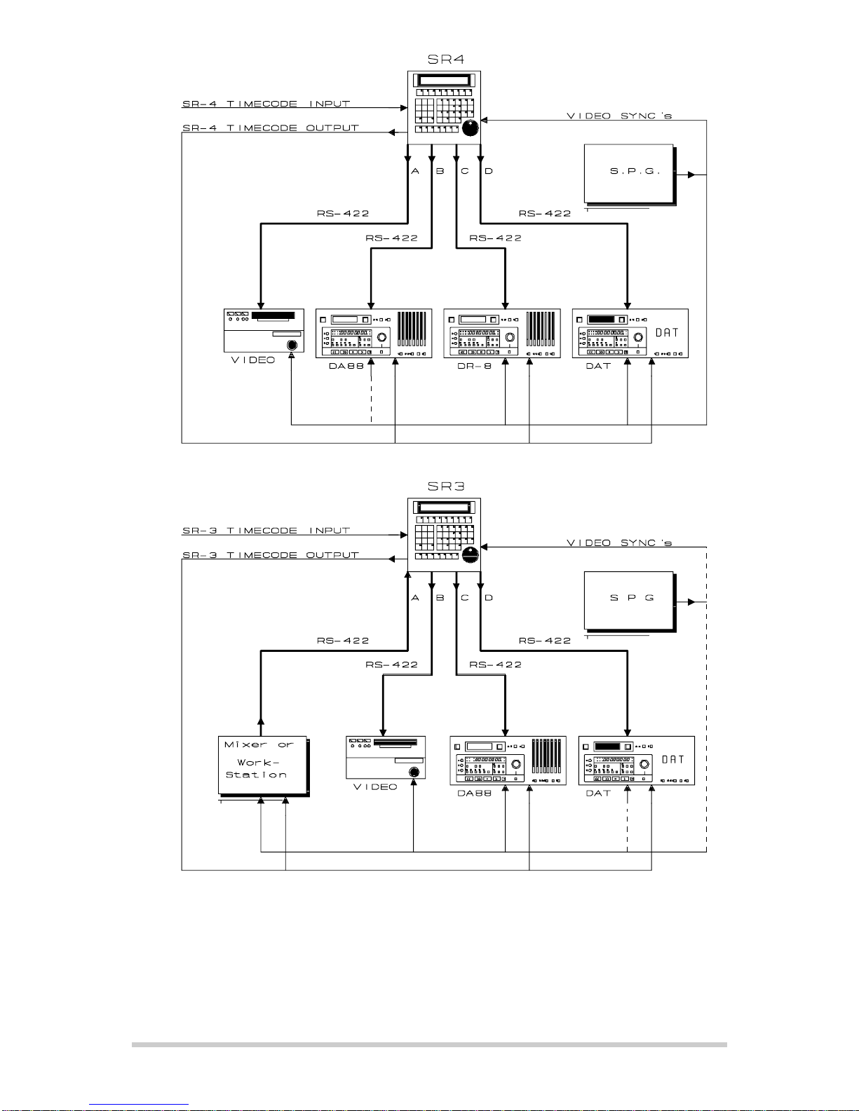
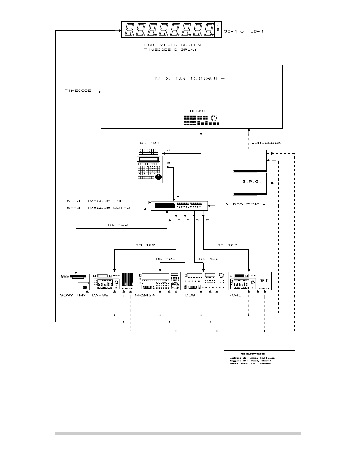
SR-3
The SR-3 may be used with a Digital Audio Work-station or Video Editor to provide control of up to 3
machines from one serial port. The DAW controls the selected master machine; the timecode output
follows the selected master. The record tracks are mapped so that the Serial input may have up to 64
record tracks. The timecode input enables the SR-3 to act as a timecode to serial converter.
SR-24
The SR-24 separates the keyboard from the electronics and display. The keyboard supports 24 record
enable keys these may be mapped to one or multiple machines. A 24 character LED display built into
the keyboard is used to display the currently selected machine and the current keyboard entry.
PARALLEL INPUT/OUTPUT
There are 6 CMOS parallel inputs and 6 TTL parallel outputs provided. Currently used as machine
control and tallies and General Purpose Trigger Outputs.
RECORD ENABLE
8(SR-3/4) or 24(SR-24) record ready switches and a bank switch are provided, these are switched with
the machine selects and provide access to up to 48 tracks on each machine.
MACRO KEYS
Any of the 100+ user functions provided may be assigned to one of the 9 macro keys. The user
functions include Dat specific functions such as PNO renumber, id write, id read. Video specific
commands such as assemble or insert, ADR keys (Next Loop, Prev Loop, Join, Insert), or system
commands such as instant replay, instant record, Mark. Continual user feedback ensures that more
functions are provided on a regular basis.
CB Electronics SR/MR User Manual 29 April 2004 SR-User 1

CB Electronics SR/MR User Manual 29 April 2004 SR-User 2

RM6-424 Connections:
Note 1: Extra RS422 input using Port A on SR424 Remote as input. For complex
installations up to 3 Sony/X-Sony inputs are available.
Note 2: RM-6 shown with optional front panel.
CB Electronics SR/MR User Manual 29 April 2004 SR-User 3

CB Electronics SR/MR User Manual 29 April 2004 SR-User 4

Contents
0.00 QUICK START, HOWTO & UPDATES
0.01 ONE FINGER TYPIST, STICKY KEYS
0.02 INSTALLING NEW SOFTWARE
0.03 RECORD ENABLE
0.04 KEY A ON THE SR-3
0.05 MASTER CHASE
0.06 MACHINE REFERENCE: VIDEO SYNCS or WORD-CLOCK
0.07 USING THE GENERATOR AS A MASTER
0.08 CRASH RECORD
0.09 USING THE SR-3 WITH A DAW
0.10 CONVERTING SR-4 -> SR-3
0.11 Setting the Pre-Roll, Start Time, Loop Delay, Post-Roll, Record Advance and End Time
1.0 Multi Machine Synchronizer Set Up
1.01 The SR-4 as a multi-machine synchroniser
1.02 SR-4 BLOCK / SR-3 BLOCK
1.03 SR-4 Timecode Output
1.04 SR-4 Timecode Input
1.10 Setting up the System
1.11 Defining the Master
1.12 SR/MR Timecode Generator Output
1.13 Defining a Machine as a Slave
1.14 Displaying the Chase Group
1.15 Entering a Offset
1.16 Trimming a Offset
1.17 Entering a Negative Offset
1.18 Pre-Roll
1.19 Post-Roll
1.20 Delay
2.0 DISPLAY
2.01 STATUS INDICATOR
2.02 MACHINE NAME
2.03 POSITION
2.04 CURRENT ENTRY
2.05 PREVIOUS ENTRY
2.06 MESSAGE TO USER
2.07 RECORD BANK
2.08 SR24 KEYBOARD DISPLAY
2.09 ERROR MESSAGES
3.0 KEYBOARD
3.01 SHIFT
3.02 STORE / RECALL / TRIM - / TRIM +
3.03 TRIM + / TRIM -
3.04 RECALL-RECALL
3.05 LOCATE
3.06 INSTANT REPLAY
3.07 AGAIN
3.08 MARK
3.09 CHASE GROUP SELECTION
3.10 RECORD ENABLE
3.11 MASTER MACHINE
3.12 CHASE (SLAVE) MACHINE
3.13 RECORD TRACK ENABLES
3.14 RECORD BANK
3.16 RM-6/Video Slave [CMD] (originally [Number])
3.17 RM-6/Video Slave [Offset]
CB Electronics SR/MR User Manual 29 April 2004 SR-User 5

4.0 AUTO RECORD & ADR/TAKER MODES
4.01 LOOP MODE OFF
4.02 REHEARSE MODE
4.03 AUTO RECORD MODE
4.04 MANUAL RECORD MODE
4.05 REVIEW MODE
4.06 NEXT LOOP
4.07 PREVIOUS LOOP
4.08 JUMP TO LOOP ???
4.09 JOIN LOOP
4.10 INSERT LOOP
4.11 DELETE LOOP
4.12 CYCLE : Record Out Enable
4.13 TALENT CUEING: Streamer
4.14 BACKUP DAT
4.15 RECORD ADVANCE
4.16 Streamer/Wipe Trigger output
4.17 Beep output
5.0 MACRO KEYS
5.01 DEFINING A MACRO KEY
5.02 READING A MACRO KEY
5.03 HARD RESET PROGRAMMING OF MACRO KEYS
5.10 Some Useful Macro’s
5.11 Shifter control :- Macro’s 68, 69 and 70
5.12 Instant Record :- Macro 74
5.13 Auto Input Monitor :- Macro 110
5.14 Display Generator : Macro 118
5,15 Step Forward and Reverse : Macros 126 & 127
5.16 2*, 4*, 6* Wind :- Macro’s 134,135,136
5.17 Red Light
5.18 One Key Post Sync :- Macro 150
5.19 Loop:- Macro 176
5.20 Varispeed : Macro’s 96, 203,204
6.00 OFFSET
6.01 Direct entry of Offsets
6.02 Auto Offset Calculation
6.03 Trimming the Offset
6.04 Entering a Negative Offset
6.05 Sub-Frame Offsets
6.06 Clear all Offsets
6.07 Offset Change Lockout when Record Enabled/Master
6.08 Shifter (Available Macro’s on SR-4, SR-24 as standard)
6.09 Using the shifter to nudge offset’s
6.10 The Colour Frame key
6.101 Colour Trim
6.11 Mixed Code
6.111 Mixed Code & Offset
6.112 Mixed Code Passing through Zero/Midnight.
6.20 Offset and record In
7.00 SETUP
7.001 ROOT: Select Set-up Required
UNIT SETUP
7.002 Unit Select Menu
UNIT RECORD
7.03 Initial Record Command
CB Electronics SR/MR User Manual 29 April 2004 SR-User 6

7.04 Check Lock Status
7.05 Master/Rec Enab Offset change
7.06 Virtual Record Tally
7.07 Track Arm Keys
7.08 Record Track Arm
7.09 System Ready Length
7.10 External Track Arming
7.11 Check for Record
7.12 Record Command to
7.13 Record-In and Record-Out Keys
7.14 Default Analogue and Video Record Ready
7.15 Default Record Enable
7.16 Record Disable Transport Keys
UNIT CHASE
7.17 Default Chase Type
7.18 Wait for Slaves?
7.19 Group Locates
7.20 Master when in Play
7.21 Input Lock Tally Source
7.22 Chase Key Function
UNIT TIMECODE
7.23 Timecode Standard
7.24 Film Speed
7.25 Default Timecode Standard Source
7.26 Slave Tally Source
7.27 TC Reader -> Port
7.28 TC Reader Incremental and direction test
7.29 (System Frame Reference) or (Generator User)
UNIT GENERIC
7.30 Macro Protection
7.301 Installing New Software
7.31 Serial A type (4 Port System) / Serial E type(6 port System)
7.32 Locate with pre-roll
7.33 GP Outputs 4, 5, 6
7.34 CP Output 3
7.35 Remote FWD/RWD Commands to Video Machine
7.36 Enable Auto-In when NOT Play
7.37 Setup Access
JOG7.38 Jog Response
7.39 Jog Wheel
7.41 IFACE Select Menu
INTERFACE RECORD
7.42 Record Tracks
7.43 Analogue and Video Record Ready
7.44 Record Tally Source
7.45 Record Command Type
7.46 Command Reinforce
7.47 Record Advance
7.48 Track Ready Tallies
7.49 Send Record In & out
7.50 Wait after Lock Tally
7.51 Crash Record Set Generator
7.52 Crash Record Reset
CB Electronics SR/MR User Manual 29 April 2004 SR-User 7

INTERFACE CHASE
7.53 Chase Command Type
7.54 Start Advance
7.55 Park Offset
7.56 Wait for Code to Stabilise
7.57 Max Slew Speed
7.58 Wait for Lock Tally
7.59 Use Servo Lock or Play Tally
7.60 Acceptable Error Window after initial lock
7.61 Serial Position Request
7.62 Slew Command Type
7.63 Reverse Slew Command
7.64 Locate Speed
7.65 Locate Type
7.66 Sub-frame offset
7.67 Continuous T/C Chase
7.68 ProTools Play, No Audio
INTERFACE GENERAL
7.69 Select Machine Type
7.70 Position Source
7.71 Pause/Stop Command
7.72 Timecode Standard Source
7.73 Command Enable
7.74 Auto Unlace Enable
7.75 Colour Framing
7.76 RS422 Position Offset
INTERFACE TYPE
7.78 Select Protocol
MIDI INTERFACE
7.79 MIDI Address
7.80 MIDI Position
AK ES 1.11/1.12 SETUP
7.81
TLS SETUP
7.82 Playback Head
7.83 Machine Type
Auto / ADR
7.84 Edit Existing / New ADR List / Options
7.87 Auto-Rec., Rehearse, Review Mode/Commands
7.88 At end of Auto-Record
7.89 ADR Backup Machine
7.90 Constant Offset Mode
7.91 Auto-Inc Loop
8.00 RESET
8.01 POWER UP RESET
8.02 FRONT PANEL RESET
8.03 HARD RESET
8.04 MANUAL HARD RESET
9.00 RECORD TRACK MAPPING
9.01 SR-24 Auto Track Mapping
9.02 Checking the current track map
CB ELECTRONICS LTD

9.03 Analog 1-4, Video, and Assemble
9.04 SR-24 Custom Mapping
9.05 Track Mapping Keys
10.00 VARISPEED
10.01 Varispeed Macro keys
10.02 Lynx operation in varispeed mode
10.03 SR/MR/RM-6 Modification
10.03 Timeline Lynx Modification (Mark I)
CB ELECTRONICS LTD

0.00 QUICK START, HOW TO & UPDATES
Thankyou for buying a CB synchroniser we hope its works as well for you as is has for all our other
customers. If you have any questions or suggestions please contact us by email
To Control individual machines
Connect the machines to ports A-D on the SR-4 or Sr-24 or ports B-D on the SR-3 using standard 9
pin cables (SR-Tech T5.03). If you wish to connect a machine to port E on the SR-24 you will need a
Tx-Rx invert cable (SR-Tech T5.04).
Connect video syncs to the SR/MR Hub and to all machines, the system will not operate correctly
without video syncs. Audio machines may be used as slaves with wordclock and master timecode
instead of video syncs, the Rosendahl nanosyncs is a good solution to generate both wordclock and
video syncs or wordclock from video syncs.
For most installations the controller will now recognise all the machines connected and automatically
configured to the connected machines. To select a machine use one of the green keys labelled A..D.
The name and current position of each machine will be displayed on the left of the LCD display. If the
incorrect name is displayed then the SR/MR will not auto configure correctly. Check the actual machine
setup is correct as some machines (DA-88, DA-98, DA-60, Pro-Tools...) have selectable ID, Section
T4. in the Sr-tech manual will help with the machine setup if we have information on the machine.
You should now be able to control each machine individually, to check the locate enter a valid timecode
number (you will see the number in the lower right of the display) and then depress the locate key The
selected machine will locate to the point or to pre-roll before the point. In doing this you have learnt one
of the main principles of operation, enter the number first then the action key. Also notice that the action
(locate) is confirmed in the keyboard display.
You can now record enable any machine as described below and track arm, As machines are record
enabled and armed they will be displayed above the keyboard display. If you are brave you can record
onto the machine as well. Press play, wait for the lock tally and then depress the record key to enter
record, use the play key to exit from record.
To Control multiple machines
Connect the SR/MR timecode output to any machines that have built in synchronisers, and to any
outboard equipment that needs a timecode feed (Best to use a distribution amp). Connect timecode
to the desk for automation, you may need to use the separate locked play timecode output for this. You
now need to learn some new terms.
Master Machine: When controlling a group of machines the commands are sent directly to the Master
Machine. Normally the video machine is used as the master for fine control when jogging.
Perfect Machine/Virtual Master: The timecode generator when used as the Master machine, called
perfect as there are no timecode dropouts and locates are instantaneous.
Slave/chase Machines: These machines follow/chase the master machine, the only user commands
sent directly to these machines are record, track arming and offset.
Offset: The positional difference between the master position and required slave normally 00:00:00:00
if the time-codes are identical.
Master Position + Master Offset = Slave Position + Slave Offset
Difference: The difference between the slave machine position and required position including the
offset.
Refer to Section 1. of this manual for a details on how to setup a multiple machine system.
0.01 ONE FINGER TYPIST: STICKY KEYS
The following keys on the SR are designed for ’One Finger Operation ’Recall’’Store’,Trim +,’Trim
CB ELECTRONICS LTD

-, and ’Shift’. They should be depressed first and then whilst the LED is lit (Approximately 5
seconds) indicating that the function is active the next key should be depressed.
0.02 INSTALLING NEW SOFTWARE
When new software is fitted always install the Factory Default parameters by selecting Root | Unit
| Generic | Menu 30: Macro Protection and select 2=Factory Default.
0.03 RECORD ENABLE
It is not possible to arm a track on a machine from the SR unless machine is record enabled. After
Hard Reset all machines are disabled.
CHECKING MACHINE RECORD ENABLE
The machines record enable status may be checked from STOP by holding the [Record] key
depressed, the four (five on the SR-24) machine select keys [A,B,C,D,(E)] LED’s will then indicate
the record enable status. The Record Enable Status of the machines may also be displayed in the
upper right of the display.
CHANGING MACHINE RECORD ENABLE
The record enable status of individual machines may be changed in STOP by depressing the
machine select keys [A,B,C,D,(E)] whilst holding down the [Record] key. The current selected
machines Record Enable may be changed by using [Shift] followed by [Record]. A Record Enable
macro key (Macro 143) is also available.
REHEARSE
Note: When Rehearse is enabled the [Record] key becomes a Rehearse on key.
RECORD/EDIT ON
To send a record command the machine must be in PLAY, then depress the RECORD key.
RECORD TRACK SELECT
To check which machine/track a track enable key is pointing to, use RECALL followed by the track
enable key.
VIDEO MACHINE ENABLE
The Analogue track selects and Video track selects have a second level of protection located in the
SETUP menu under Root | IFace | Record | Menu 41: Analog and Video Record Rdy.
RECORD INHIBIT
The system will inform you if the record inhibit is set on a tape. Some machines also have a record
inhibit on their serial port or have user selectable track mapping (DA-88, DR-8, DD-8!) .
0.04 SWITCH ’A’on the SR-3 or ’E’on the SR-24
On the SR-3 port Ais used as a control input to the SR-3. you may Enable/Disable the remote
control input using the [A] key, External control is enabled when the [A] LED is ON (This has
changed it was originally On for Disable).
0.05 MASTER CHASE
Depressing the CHASE key when the master is selected will send chase on/off commands to all
machines that are group chase enabled. Selecting a machine and enabling/disabling chase will
enable/disable the chase group status.
0.06 MACHINE REFERENCE: VIDEO SYNCS or WORD-CLOCK
In all digital environments it is preferred to lock machines to Word Clock and not video syncs. In this
case it may not be possible to use RS-422 only to slave machines. In this case it is recommended
that the machines internal synchroniser be used to chase a master timecode feed.
Note. The SR-3/4 always requires video syncs.
0.07 USING THE GENERATOR AS A MASTER
The key GEN (Macro 118) enables the Generator, the generator is always slaved to the current
master machine. To enable the generator as a master use SHIFT followed by GEN in the normal
CB ELECTRONICS LTD

way.
0.08 CRASH RECORD
To perform a crash record on one or more machines the following conditions must be met
1) The machine must be record enabled.
2) Menu 41:- Analogue and Video Rec. Rdy must be set to 3=Asmb on each machine.
3) The machine must be in STOP
4) Arm track 8(Crash) in the AV+ASMB bank
5) Setup | Root | Unit | Record | Menu 3:- Initial Record command must be set to 0= Record
Depress the Record key and the Play key (Record first) to send a crash record command to all
record & assemble enabled machines.
The Machines internal Generator will be preset to the machine Record in Time.
note: If the current selected machine is in play then any machine that is in play, track armed and
record enabled will go into record when the record key is depressed.
0.09 USING THE SR-3 WITH A DAW
Any DAW that can control a Video Machine via RS422 may be used wit the SR-3 to control up to
3 machines. The SR-3 may also be used as a timecode and RS4-22 switcher for the DAW.
The serial control cable normally connected to the video machine should be connected to Port-A on
the SR-3. The timecode input on the DAW (if required) should be connected to the timecode output
on the SR-3.
The [A] switch on the SR-3 is used as a local remote switch, in order for the DAW to control the
system the [A] LED should be ON. The DAW will directly control the current SR-3 master, to define
the master use Shift followed by the machine key (B,C,DorE).
0.10 CONVERTING SR-4 -> SR-3
To change the direction of Port-A (SR-4/3) or Port-E (SR-24) from Output to input:-
1) Setup Root | Unit | Generic | Menu 31: Serial A type (alternately use [3] [1] [Recall] [Setup]) and
select Serial A type 1= I/P (SR-3).
2) Either use a TX-Rx invert cable to connect to port A, or Change the 4 internal links on Port A to be
parallel to the back panel as per the diagram at the end of this manual.
Once configured as an input the following changes are made to the unit.
1) The controller connected to port A will control the currently selected master (B, C, D).
2) Key [A] will become a local Switch, when the LED is illuminated this will enable control from port A.
0.11 Setting the Pre-Roll, Start Time, Loop Delay, Post-Roll, Record Advance and
End Time
To Set the Pre-Roll, type in the required pre-roll, then press Store followed by Reverse Play (<).
To check the Pre-Roll depress Recall Followed by Reverse Play (<).
To Clear the Pre-Roll, Clear the keyboard display (0or Shift followed by 0)
The Pre-Roll is used with Locate when using multiple machines to allow time for the
slave machines to lock. To locate without Pre-Roll use Shift followed by Locate.
Start Time use the Rewind (<<) key instead of the Reverse Play key.
The Start time is particularly useful when using open reel or film machines, in rewind
when the tape is within approximately 1 minute of the start time a locate to start time
command will be issued to the machine.
Loop Delay use the Stop key.
Post Roll use the Play key.
Record Advance use the Record Key.
End use the Forward Wind (>>) key.
CB ELECTRONICS LTD

1.00 Multi-Machine Synchronizer Set Up
The SR/MR series of synchronizers offer two forms of synchronisation using either the SR/MR
synchronizer or where available the machine’s built in synchronizer. The user interface is identical. The
decision "which type of synchronisation to use" depends on the users requirements and the technical
details of the machine and the installation.
When a new machine is connected the a system parameter (Unit | Chase | Menu 17 System Chase
Type) determines which type of synchroniser to use if there is a choice. Once connected the user is
free to change the synchroniser type. The user selection will only be changed after a hard reset or if
the machine connected to the port is changed.
1.01 The SR-4 as a multi-machine synchroniser
Please ensure that you have a copy of the drawing SR-4 Block / SR-3 Block whist reading this
section. The SR-4 may be used as a 4 machine remote control only, however because control of
both offset and chase are included the SR-four may be used as a 4 machine synchroniser. One
machine, the timecode reader, or the timecode generator may be chosen as the master. The
remaining machines will slave to the selected master.
For serial controlled machines a single SR-4 can replace five Timeline Lynx II modules and a KCU
controller. Where parallel controlled machines are used your existing Timeline Lynx I/II, AK ES-1.11,
Studer TLS4000, or AS Zeta 3 synchroniser module may be used with the SR-4.
1.02 SR-4 BLOCK / SR-3 BLOCK
This diagram shows a typical SR-4 installation, the four machines may be any selection of 9-pin
controlled machines. Note the Video Reference is sent to all machines.
1.03 SR-4 TIMECODE OUTPUT
The SR-4 timecode output follows the position of the selected master machine (including the SR-4
timecode input). The timecode generator position is calculated as follows:- [Timecode Output] =
[Master Position] - [Master Offset]. Including the master offset in the calculation allows the user to
change the master without having to update all the slave offsets.
The timecode generator output is also used in the perfect machine mode to provide a timecode
master in a tapeless studio.
1.04 SR-4 TIMECODE INPUT
The SR-4 timecode input may be used as a remote timecode master. All four machines may be
slaved to this timecode source. In order to use the SR-4 timecode input a macro key must be used
to display the timecode (Macro 113).
1.10 Setting up the System
1.11 Defining the Master
Any machine on the system may be defined as the master including the generator or the reader. The
master machine is defined using [Shift] followed by a machine key (A, B, C, D, E (SR-24)), [Reader]
or [Generator]. Once the master has been defined and offsets set for all the slaves the master machine
may be changed as required. Note: on MR systems only machines controlled directly by the controller
may be defined as a master machine and not machines controlled by the MR-3’s.
The master of a multi-machine system is the machine to which all commands are sent. The other chase
enabled machines then follow the selected master.
The master is the machine over which the user has direct control. Each user has his own reasons for
selecting a particular machine as master, here are some:-
1) Film because it is the slowest.
2) Video so that the user can jog the picture directly.
3) The record machine so that it is first to lock.
4) A machine that slaves badly or not at all.
CB ELECTRONICS LTD

5) The Generator as a "Perfect Machine".
6) The Reader where the master is not directly controlled.
The system will only operate correctly if the selected master is resolved (locked) to video syncs.
Note. When configured as a SR-3, where [A] is an input ([E] on the SR-24) [A] should never
be defined as the master. This is an input and not an output. Any controller connected
to this input will control the selected master machine.
Perfect Master Mode
The timecode generator may be selected as the master (Shift followed by Gen (Macro 118)) to
enter the perfect machine mode. The generator may be used as a timecode master in a tapeless
studio. To set the value of the timecode generator use the Locate/Shift Locate command.
Remote Master Mode
The timecode reader may be selected as the master ([Shift] followed by [Reader]. This is used
when you have a remote source of code only. Not the code should be resolved to the same video
reference as the studio. The SR keyboard may be used as a parallel remote control. To do this
select Setup | Root | Unit | Generic | Menu 33: GP Outputs 4, 5, 6 and choosing 5=RdrCmd
(See section 7.026). Connecting a suitable parallel interface GPI outputs 4, 5, 6 will enable the
SR/MR to control the source of the external timecode.
Note: The Remote timecode MUST be locked to video syncs in order to work correctly.
1.12 SR/MR Timecode Generator Output
The SR/MR timecode generator is an integral part of the synchronization system. The timecode
value follows the position of the selected master machine (including the timecode reader). If Group
Locates are enabled (Setup | Root | Unit | Chase | Menu 19; Group locates), the timecode
generator will jump to the Locate point allowing chase machines to locate individually. The timecode
generator output will roll over any drop-outs in the machine timecode.
By using the timecode generator output chase only machines may be connected to the system for
playback.
The timecode generator value is calculated as follows:- [Timecode Output] = [Master Position] -
[Master Offset]. Including the Master Offset in the calculation allows the user to change the master
without having to update the slave offsets, or change the settings for any other units connected to
the SR-4 timecode output (Automation, Midi, Chase only slaves...).
1.13 Defining a Machine as a Slave
A machine may be selected to be a slave by selecting the machine (A, B, C, D or E) and using
[Chase/Offset]or[Shift] followed by [Chase/Offset]. When the [Shift] key is used the current
Master and Slave Positions are used to calculate the Slave Offset.
1.14 Displaying the Chase Group
When any machine in the chase group is selected then the LED’s of all the machines within the
group are illuminated. The selected master machine’s LED will flash.
1.15 Entering an Offset
To enter an offset, first select the machine (A, B, C, D or E) then type in the offset required, this will
be displayed on the lower right hand display. Then use the Store key followed by the Chase/Offset
key. The display will confirm by displaying offset next to the displayed number.
1.16 Trimming an Offset
To trim an offset (or any other memory) first enter the amount of trim required, this will be displayed
on the right of the lower line. Then use the Trim+ or Trim- key followed by the Chase/Offset key.
The display will confirm by displaying the new offset.
1.17 Entering a Negative Offset
On the SR and MR series remotes all offsets are calculated on a twenty-four hour clock. To enter
CB ELECTRONICS LTD

a negative offset either calculate the required offset by subtracting from 00:00:00:00 (-01:00:00:00
= 23:00:00:00) you can use the SR-4 to perform the calculation as follows:-
1) Zero the keyboard display: Shift followed by Clear/0
2) Zero the offset: Store followed by Chase/Offset.
3) Type the required negative offset.
4) Subtract: Trim- followed by Chase/Offset.
1.18 Pre-Roll
When more than one machine is used it will take time for all machines to become synchronised after
a play command is issued. A user defined pre-roll is used with the [Auto-Record] and [Rehearse]
commands and may be subtracted from locate commands. The Pre-Roll is set by entering the required
pre-roll followed by [Store] followed by [<](Reverse Play). The default parameters are that [Locate]
is with pre-roll and that [Shift] followed by [Locate] is without pre-roll. The menu setting (Setup | Root
| Unit | Generic | Menu 32:- Locate with Pre-Roll) may be used to reverse this.
1.19 Post-roll
Post-Roll is used to ensure that exit’s from record are always clean. The Default post roll is 12 frames.
The Post-Roll is set by entering the required post-roll followed by [Store] followed by [>](Play).
1.20 Delay
Delay is used to allow external machines or the Talent time to catch up after a locate. The Default
Delay is 1 Second. The Delay is set by entering the required Delay followed by [Store] followed by [
[]](Stop).
CB ELECTRONICS LTD

2.00 DISPLAY
A two line display is used on most SR/MR units, the display area may be broken into 6 area’s3on
each line upper Left, upper middle, upper right, Lower left, lower middle, lower right.
Master Display
L A: BVW-75 * Lock * Enable B C
HH:MM:SS B:DA-88 Locate 10:12:13:00
Slave Display
L B: DA-88 - Lock - Offset 00:10:00:00
HH:MM:SS:FF B:DA-88 Locate 10:12:13:00
Auto Record Display
L A: BVW-75 Master Rec In 10:11:14:10
HH:MM:SS:FF Loop 001 Rec Out 10:12:13:00
2.01 STATUS INDICATOR Upper Left (1st character)
A single character at the start of the line 1 indicates the status of the selected machines.
LA:DA-88 1 Current Selected machine is Locked.
GB:DA-88 1Current Selected machine is locating (GOBO).
2.02 MACHINE NAME Upper Left
Situated after the status indicator on line 1, the 8 character machine indicator displays the serial port
character followed by current selected machine name (When known):-
LC:7030
When the machine name is not known the hexadecimal Device ID will be displayed
L D:$F111
If you connect a machine that displays its Device ID, please inform us of the displayed number, type,
and record setting etc. so that we can include the machine in the next revision.
2.03 POSITION Lower Left
Situated at the start of line 2 the position display indicates the position of the selected machine.
Note:
The Frames will only be displayed when the selected machine is slow or stopped.
2.04 CURRENT KEYBOARD ENTRY Lower Right
The last eleven characters of line 2 represent the current keyboard entry or the last memory
recalled. Where the memory name is known it is displayed immediately to the left of the display.
MARK 01:00:00:00
The position captured when the MARK key was depressed.
KEYBD 00:00:12:23Keyboard entry
This display position is also used to display the Record OUT time when an ADR LOOP mode is
enabled.
Auto / Rehearse / Review / Manual
This display position will display the Record OUT time when a LOOP mode is enabled unless an
entry is made to the keyboard display.
CB ELECTRONICS LTD

2.05 OFFSET/SHIFTER | Enable/Arm/Record Upper Right
The last eleven characters of line 1 are used to display multiple information as follows:-
1) Warning Message
2) Auto/Rehearse In point
3) Shifter if active
4) Offset if active
5) Enabled/Armed/Record
The actual display is dependent on the current system status, the list is in order of priority.
Auto / Rehearse / Review / Manual
This display position will display the Record IN time when a LOOP mode is enabled unless an entry
is made to the keyboard display.
Shifter / Offset on Master or Chase Enabled Machine
1) If the Shifter is not 0 then the Shifter contents will be displayed in +/- frames.
2) If the Offset is not 0 then the offset will be displayed.
Normal
1) If any machine is in Record then its letter will be displayed.
2) If any machine is armed then its letter will be displayed.
3) If any machine is record Enabled then its letter will be displayed
4) Blank
2.06 MESSAGE TO USER Upper Middle
The centre section of line 1 is reserved for messages to users, as only one message may be displayed
at a time the messages are prioritised. The following list starts at the highest priority:-
No Syncs No Video Syncs at the SR-4
No Comms No communications to the machine, check cable and serial protocol
No MR-3 MR systems only: no serial interface (MR-3 or MR-4)
Disabled All commands and status requests disabled, check menu or MR-3 front panel
Local Remote control disabled, Local control only
No Tape No tape in machine
T.Begin Tape At or close to Start, timecode may be wrong
Tape End Tape at or close to End
Unlaced Tape unlaced
Master Master selected in wind or stopped with all slaves parked
Locate Master selected and locating
* LOCK * Master selected all machines in locked play
! Slew-A Master selected and playing, machine A not locked
! Park-B Master selected and Stopped, Machine B not parked
- LOCK - Slave selected all machines in locked play
- PARK - Slave selected, All machines stopped and parked
Pk 12frm Slave selected and parking, current error +12 frames
Lk 00frm Slave selected and locked, not all slaves locked
Er 01frm Slave selected and slewing, current error +1 frame
Sht+1.48 Master selected and in Shuttle forward at 1.48 play speed
Var+1.1 Master selected and in Varispeed Play at 1.1 play speed
2.07 RECORD BANK lower Middle
The current record bank is displayed in the middle of the lower display unless auto-record or rehearse
are enabled.
B:DA-88 Machine B(DA-88) tracks 1-8
C:9-16 Machine CTracks 9-16
A:A1..A4+V Machine ATracks A1, A2, A3, A4, Video, and Assemble
D:A1..A4 Machine DTracks A1, A2, A3, A4
A: Machine ANo tracks enabled
CB ELECTRONICS LTD

D:9 3324 Machine DTrack 9 on record arm key 1
Loop 001 When the ADR mode is enabled then "LOOP" is displayed.
The bank key will only be active when more than one record bank is enabled (Setup | Unit | Record
| Menu 9: System Ready Length)or (Setup | IFACE | Record | Menu 40 | Record Tracks)
2.08 SR-24 KEYBOARD DISPLAY
The 24 character SR-24 keyboard display shows a combination of the following:-
2.01 Status
2.02 Machine Name
2.04 Current Keyboard Entry
2.09 ERROR MESSAGES
When the user enters a prohibited key sequence a error message will appear in the top right of the
display (On the SR-24 this also appears in the keyboard display). The error display will remain until you
depress another key.
1: Not Record Enabled
The machine you are trying to record arm is not record enabled see section 1.11 and 3.09. Check
the Machine:Track to which the key is assigned to using [Recall] followed by the Track Key.
If this Error message occurs after depressing the Record key to enter Record then check
Root|Unit|Record|Menu 3: Initial Record Command
2: ! Record Inhibit !
The tape in the machine you are trying to record arm has record inhibit set, or you are trying to
record enable a Playback Only Machine.
3: !System Not Locked
Attempted to enter record when the system is not locked, See section 7.006. Note this error will also
occur if Setup | Root | Unit | Record | Menu:8 Record Track Arm is set to 2= Record and you try
to enter record when not in play!
4: ! Key Lock On !
Macro 138 disabled the last key depressed, If you do not have this macro key fitted then it will be
necessary to hard reset the unit as the memory has become corrupted.
5: ! OUT before IN !
Not possible to perform an Auto-Edit or Rehearse. If you are not using the record out then use Clear
([Shift] followed by [0]),followed by [Store] followed by [Out] to disable the out point.
6: ! Comms-Local-Tape
The machine to selected or the master machine is either not communicating, switched to local, or
has no tape.
7: ! Macros Protected
Not possible to change macro’s see Setup | Root | Unit | Generic | Menu:30 Macro Protection.
8: ! No Track Mapped!
Use Recall followed by the Track arm key to check the track mapping see section 9.00 and T2.00.
9: Master/Rec Enabled
Changing the offset on a record enabled machine or the Master is not allowed. If it necessary to
change the offset disable the record first or change Unit|Record|Menu 05 Master/Rec Enab Offset
Change, See Section 7.05.
10: !Locate to Start!
If Rewind is active and the selected machine is within a window defined by Root | Iface | Chase
CB ELECTRONICS LTD

| Menu 50:- Locate Speed of the user defined start ([Recall] followed by [<<]) then a Locate to
Start command will be issued. To disable/enable this feature enter the required start time then
[Store] followed by [<<]. Setting a start time of 00:00:00:00 will disable.
11: TC Jump or Pre-Rol
Record in point missed due to timecode edit or insufficient pre-roll to allow the backup DAT to lock
and record it’s ident.
12: !Commands Disabled
Commands to the Selected machine or Master are disabled, see menu Root | IFace | General |
Menu 58: Command Enable (On MR-3 check front panel switch).
13: !Video Not Stopped
Changing of edit mode when in play is inhibited on video machines because of the head switching,
Stop machine to change.
14: !Alg & Vid Enable!
The track you are trying to arm is disabled in Root | IFace | Record | menu 35: Analog and Video
Rec Rdy.
15: !Not all in Record
During an Auto-Edit, not all armed machines entered record. See Setup|Root|Auto/ADR| Menu 86:
Check for Record
Ampex Protocol: This message is given during an edit if the Record Lockout/Inhibit on the machine
is on.
16: ! Crash Enabled !
Command is not possible because the selected machine or Master is Crash Record Enabled.
17: ! No Tape !
No Tape in machine
18: !Macro Not Fitted!
Macro Number as defined by key not implemented in the software. (Usually because a 27C256
Eprom is fitted).
19: !No Macro defined!
No Macro defined for key, enter macro number followed by [Shift], followed by [Store], followed by
key.
20: !Not In Record!
21: !No Tracks Armed!
Auto-Edit attempted with no tracks armed.
22: !No EEPROM Access!
EEprom not found during power-up, reset unit using small reset button or power on and off. If
problem persists contact CB Electronics.
23: !Backup Machine!
Chase command may not be issued to the backup machine. See Setup|ADR/Auto|Options|Menu
79: Backup Machine
24: !Rec Out Disabled!
Record out disabled by Macro Key 75 (Enable Rec Out).
25: ! System in Local!
A remote command received and ignored on input A/E or F whist the System is in Local.
26: Command not Fitted
A remote command received that is not fitted to software.
CB ELECTRONICS LTD

27: Master Not in Play
Record command not sent to Backup machine because the master was not in play.
28: No Record Rehearse
Record command from user ignored because in Rehearse or review mode.
29: !No Comms From SSL
If S88 interface fitted then no connected to SSL 4K computer.
29: Mcn Record Assigned
30: !Use After Shift
Key only operates when Shift LED illuminated.
31: !Number Lock On!
RM-6 only, Machine commands locked out, [SHIFT] + [NUMBER] to enable/disable.
32:! Backup not Armed
Auto Record: The specified back-up machine is not armed.
33: Backup Local-Tape
Auto Record: The specified backup machine has no tape
34: Disabled in Record
This key/command is disabled by Menu 16: Record Disable transport Keys
35: Fit 24C08 EEPROM
In the seven years since the SR/MR were originally designed the number of parameters has
increased. The latest units are now fitted with 27C512 EPROM’s in place of the original 27C256
(You may need a Hardware update for this). 62256 RAM’s in place of the original 6264 RAM. 24C08
EEPROM’s in place of 24C02 or 24C01 EEPROM’s. It is recommended that if you wish to take
advantage of the latest features that you upgrade U15 (RM-6N: U19) to 24C08.
The EPROM is always socketed
The RAM is always socketed
The EEPROM is normally soldered, it is a 8 pin chip on the right hand side of the PCB. Cut all 8
legs and use a solder sucker to remove all legs. Fit a turned pin socket and then fit the new
EEPROM (Cost Approx £1 from RS.
36: Reset to Factory
Unit and IFACE parameters reset to Factory defaults.
37: Reset to User
Unit and IFACE parameters reset to last parameters saved.
38: Port Not Available
Serial Port not available, it may be defined as input.
39:! Shift / Password
To access Setup Menu use [Shift] followed by [Setup] key. To recall menu page enter page
number then [Shift] followed by [Recall] followed by [Setup]. If Password software installed then
enter password.
CB ELECTRONICS LTD
This manual suits for next models
5
Table of contents
Popular Recording Equipment manuals by other brands

Digital Audio Labs
Digital Audio Labs LIVEMIX DA-816 user guide

Korg
Korg volca sample owner's manual

Tando
Tando TR-71S user guide

Martin Audio
Martin Audio M3 - SCHEMATICS user manual

Sony
Sony Memory Stick PRO Duo MS-MT Series operating instructions

Dynojet
Dynojet POWER COMMANDER III installation instructions