ccei PHENIX User manual

PHENIX
Technical Manual
v2.0
CCEI
page 1
pH regulation and
ORP analysis
for salt electrolysis
Technical Manual
V2.0
Code Version
Date
MPNT0108
V2.0 03/08/2015
CONTENTS
TECHNICAL CHARACTERISTICS .................................................... 2
OVERVIEW ....................................................................................... 3
pH ........................................................................................... 3
Re ox ..................................................................................... 3
OPERATION ..................................................................................... 4
Display.................................................................................... 4
pH Menu ................................................................................ 6
Oxi ant Menu ...................................................................... 8
Settings Menu ....................................................................... 9
HYDRAULIC CONNECTION ........................................................... 10
Installing the sensors ............................................................ 10
Installing the injector ........................................................... 10
Installation iagram ............................................................ 11
ELECTRICAL CONNECTION .......................................................... 12
SENSOR MAINTENANCE ................................................................ 15
Caution: Please read these instructions carefully before installing, commissioning or
using this appliance

PHENIX
Technical Manual
v2.0
CCEI
page 2
TECHNICAL CHARACTERISTICS
General
Dimensions (l x h x d) in
mm Weight
Power supply
Protection Index
300x150x90
2 kg
230V / 50Hz
IP-55
Class II
pH
-
meter
Measurement range
Measuring resolution
Sensor
Calibration
Correction (offset)
Dosing Pump
Type
Max. flow rate
Dosing
Volume control
3.9 to 9.9
+/- 0.1
Combined electrode
at pH 7 and pH9
+/- 0.5
Peristaltic flow
1.8 l/h
Proportional 0 to 0.9l/h
Daily and total
RedOx Analysis
Measurement range
Sensor
Calibration
10 to 990mV
Combined electrode
to 650mV
Accessories supplied
•
4 m of crystal tube.
•3 x Sockets in 50 mm
•1 Suction strainer for pH corrector
•1 x Injector
•1 x pH7 Calibration solution
•1 x pH9 Calibration solution
•1 x 650mV Calibration solution
•1 x pH sensor
•1 RedOx (ORP) sensor
•2 x sensor holders
•1 enslaving cable
Menu 8 different languages
French, English, German, Spanish,
Italian, Portuguese, Dutch, Czech
W
HEN THE DEVICE IS IN “DOSING” MODE
,
THE PUMP DOES NOT TURN CONTINUOUSLY
BUT TURNS FOR A FEW SECONDS AT
1
MINUTE PER
2
MINUTE CYCLE
.
C
AUTION
: T
HIS EQUIPMENT IS SPECIFICALLY DESIGNED FOR CORRECTING THE P
H
OF
SWIMMING POOLS
. I
F USING ANOTHER TYPE OF SOLUTION
,
CONSULT THE MANUFACTURER TO
VERIFY COMPATIBILITY
.
HYDROCHLORIC ACID OF OVER
10%
IS NOT RECOMMENDED
.

PHENIX
Technical Manual
v2.0
CCEI
page 3
OVERVIEW
PHENIX is a complete regulation system for salt electrolysis. Combined with a salt
chlorinator, PHENIX regulates its chlorine production and adjusts the acidity (pH) of
the water.
PH
The pH or Hydrogen potential measures the degree of acidity present in water. It is
measured on a scale of 0 to 14. A solution with a pH of 7 is neutral. If it is below 7, the
solution is acidic, above 7 the solution is considered basic or alkaline.
To ensure the comfort of swimmers, the effectiveness of the treatment and reliability
of the installation, the pH of the swimming pool water must be maintained at around 7.
A pH of between 6.8 and 7.6 is generally considered to be correct.
Water that is too acidic (pH <6.8) irritates
the mucous membranes, corrodes
100
90
80
70
60
50
40
30
20
10
0
5.5 6.0 6.5 7.0 7.5 8.0 8.5 9.0 9.5
pH
metal parts and may damage plastic
elements in the pool (liners).
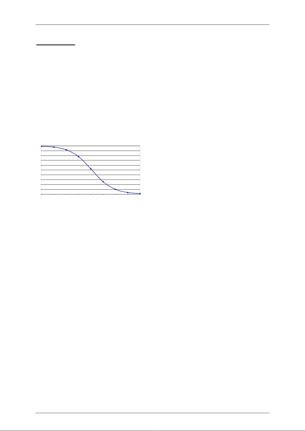
Water which is too alkaline (pH >7.8) can
also be aggressive (caustic) and
considerably reduce the effectiveness of the
chlorine. Thus, when the pH goes from 7.2
to 8.2, the percentage of active chlorine
changes from 70% to 20%.
To ensure the optimum effectiveness of the
treatment, it is therefore essential to
maintain the pH of the water between 7.0 and 7.6.
In addition, the salt chlorinator causes an increase in pH which makes pH regulation
particularly useful.
PHENIX maintains the pH of your pool by injecting a pH correcting solution into the
water as required. The user can configure the PHENIX in pH- mode or in pH+ mode.
In pH- mode, the PHENIX injects PHminus (acid) to lower the pH in the pool and in
pH+ mode it injects PHplus (base) to increase the pH. PHENIX, specifically designed
for swimming pool water, regulates the pH between 6.0 and 8.5.
To reduce the difference with the set point value, regulation is proportional: The dosing
speed increases the greater the difference with the set point value. The injection flow
rate can vary between 0.1 l/h and 0.9 l/h.
REDOX
PHENIX measures the oxidation reduction (RedOx) potential of the water in your pool
and if this potential is below the set threshold, PHENIX activates chlorine production
from a chlorinator.
The salt water chlorinator separates the salt (NaCl) into sodium (Na) and chlorine (Cl).
which immediately dissolves in water to produce hypochlorous acid (HClO). This
powerful disinfectant destroys bacteria and its presence affects the oxidation reduction
potential measured by PHENIX.
This RedOx potential, or ORP (which stands for Oxidation Reduction Potential), is
expressed in millivolts (mV) and gives an indication of the disinfectant capacity of the
water, and thereby the quality of the water in the pool (or its sanitary status). The higher
the potential, the greater the disinfectant power
Active Free Chlorine
%

PHENIX
Technical Manual
v2.0
CCEI
page 4
of the water. Generally, the potential should be between 550mV and 800mV. For public
pools, regulations require a minimum potential of between 650mV and 750mV,
depending on the country.
Even though the device is calibrated in the factory, it is recommended to periodically
calibrate the sensors and also the first time the device is put into operation in order to
ensure the reliability of the measurement. To do that, simply follow the instructions in
the CALIBRATION paragraph.
OPERATION
The system is switched on using the switch on the front of the device.
PHENIX has a drop-down menu so you can see the status of the different PHENIX
variables. In addition, this drop-down menu allows you to access the
“SETTINGS” menu used to configure the device.
DISPLAY
The and keys on the keyboard are used to scroll through this menu. The
different displays on this menu are as follows:
The measured RedOx (ORP) potential is shown on the left in mV
1
. A “P” appears if the
chlorinator is asked to produce chlorine then an arrow indicates if filtration is
operational. The measured pH
1
is then displayed.
Messages in the system status are displayed alternately on the screen:
Stat
us
Description
Att. Filt The filtration pump is off. Regulation on hold.
pH/24>> The max. volume of product injected per 24 hours
has been exceeded. Waiting for the next 24 hour
period
Container Tank Indicates that the container is empty. Waiting for
reinitialisation of the container volume
pH > < The pH read is abnormal (>9.9 or <3.9).
Check the sensor. Repeat calibration. Check the
pH7 and pH9.1 solutions
Ox > < The ORP read is abnormal (> 990mV or <
150mV). Check the sensor. Repeat calibration.
Check the 650mV solution
1
. An asterisk indicates that the value is being obtained.
This device automates the treatment of you pool but the results of the measurements
can be affected by numerous factors and the user should remain vigilant and
periodically conduct a chemical analysis (test strips or colour indicator) to check the
consistency of the results and recalibrate the sensors if necessary.
570mV * P →pH=7.2*

PHENIX
Technical Manual
v2.0
CCEI
page 5
A second screen shows the pH function status
The left of the screen shows the pH dosing mode (pH+/pH-/ON/OFF) (cf. pH Menu).
Then the pH value measured by the sensor is displayed, followed by the programmed
set point. An arrow is displayed when the dosing pump is operating. On the right of the
screen, the volume of pH corrector injected over the past 24 hours is displayed.
A third screen shows thee ORP function status
The ORP operating mode is displayed on the left (ON/OFF/PRG/REG) (cf. Oxidant
Menu).
In PRG mode, the programmed duration is displayed alternately with the mode.
Then the actual duration of daily production is displayed followed by the time that
has elapsed since the start of the 24-hour period.
When chlorine production is activated, a “P” is displayed on the right of the screen.
The following three screens are only visible in “Installer” mode. They allow access to
the device’s internal meters and an estimate of the active chlorine concentration.
Displays the total volume of pH corrector injected since the device was put into
operation.
Displays the total chlorine production since the device was put into operation.
The hypochlorous acid concentration (Active chlorine) is calculated based on the ORP
and pH. The result is expressed in ppm, equivalent to mg/l. This values is calculated
according to the parameters measured by the PHENIX and a theoretical formula
combining pH, ORP and temperature but is provided merely as an indication and
should not be a substitute for a chemical analysis.
pH+ 7.6/7.2 >> 1.5L
REG 04:13/08:30 P
pH: 00.00L
Cl Prod: 00h00m
HClO = 1.3 ppm

PHENIX
Technical Manual
v2.0
CCEI
page 6
PH MENU
This menu is used to access the pH regulation settings. To access the pH Menu,
simply press the key.
The and keys are used to scroll through this menu. The different displays in
this menu are:
This screen allows you to choose the regulation mode. To do that, simply press the
key and choose the regulation mode using the and keys.
The different possible regulation modes are as follows:
-
pH-: to inject a pHminus product and thereby lower the pH of the pool. The pump
will start when the pH is above the pH set point.
-
pH+: to inject a pHplus product and thereby increase the pH of the pool. The pump
will start when the pH is below the pH set point.
-
ON: to inject a PHplus or PHminus product continuously without any regulation.
This mode can be used to prime the pump.
-
OFF: to prevent any product being injected. This mode can be used during
wintering for example.
To validate the mode, press the key. To exit the programme without validating
the mode, press the key.
This screen is used to define the pH set point. To change this value, simply use the
and keys. To validate the value, press the key. To exit the programme without
validating the value, press the key.
This screen is used to define the maximum permissible volume to be injected per
day. To do this, simply press the and choose the desired maximum volume using
the and keys.
The volume is adjusted in litres. To validate the set volume, press the key. To exit
the programme without validating the mode, press the key.
CAUTION If this value is left at 0 litres, there will be no restriction on the volume
injected. It is therefore advisable to set a value for this parameter.
The maximum permissible volume depends on the size of the pool and the quality of
the water used to fill the pool. This value should therefore be set by the engineer when
the device is put into operation.
Dosage pH = pH-
pH set point = 7.2
V/24h=2.0L (pH)

PHENIX
Technical Manual
v2.0
CCEI
page 7
This screen is used to define the volume of the pH corrector container.
The volume of the container is adjustable from 0 to 25L. To define the volume, simply
press the and choose the value using the and keys.
To validate the set value, press the key. To exit the programme without validating
the mode, press the key.
NOTE: As PHENIX injects the product into the pool, the value previously defined is
decreased. When this value reaches 0, the PHENIX pump is blocked. To re-enable
operation of the pump, the user should reset the container volume as described below.
If the volume is set to 0, there will be no controls on the pH corrector container
This menu is used to calibrate the pH sensor. This operation must be carried out first
time the appliance is commissioned as stated in the Maintenance paragraph.
Calibration is carried out using the two solutions supplied with the PHENIX: a PH7
solution and a PH9 solution.
To begin calibration, press the key. The PHENIX then displays CAL. pH7:x.x?. This
means that the user should immerse the sensor in the PH7 solution, wait until the pH
value stabilises and then press the key. If the value is correct, the calibration
procedure continues, if not, the Err. ! message flashes - this means you have to press
the key to start the measurement again.
PHENIX then displays CAL. pH9:x.x?. This means that the user should immerse
the sensor (after having cleaned it) in the PH9 solution and then press the
key.
If the calibration is correct, the pH Calibration message displays. If not, the Err. !
message appears and the calibration should be repeated after having checked the
solutions and the condition of the sensor. If the problem persists, contact your
installation engineer.
Cont = 20.0L (pH)
pH Calibration

PHENIX
Technical Manual
v2.0
CCEI
page 8
OXIDANT MENU
This menu is used to select the ORP regulation mode. To access the
different settings, simply press the key.
The and keys are used to scroll through this menu. The different displays in
this menu are:
This screen allows you to choose the regulation mode. To do that, simply press the
key and choose the regulation mode using the and keys.
The different possible regulation modes are as follows:
-
REG: initiates the production of chlorine if the measured RedOx potential is less
than the set threshold.
-
PRG: produces the programmed quantity of chlorine every day, whatever the
measurement.
-
ON: to continuously produce without regulation. This mode can be used in case of
ORP sensor failure. Production remains dependent on the operation of the filtration
pump.
-
OFF: to prevent the chlorinator injecting any chlorine. This mode can be used
during wintering for example.
To validate the mode, press the key. To exit the programme without validating
the mode, press the key.
This screen allows you to set the desired RedOx potential. To change this value, simply
use the and keys. To validate the value, press the key. To exit the programme
without validating the value, press the key.
This menu allows you to programme the desired production duration in PRG mode.
To change this value, simply use the and keys. To validate the value, press
the key. To exit the programme without validating the value, press the key.
Calibration of the ORP sensor is carried out in the same way as for the pH sensor.
But with a single measurement point.
Calibration is carried out using the 650mV solution supplied with the PHENIX device.
Ox Prod = REG
ORP limit = 660mV
Prod/24h= 08h
Ox Calibration

PHENIX
Technical Manual
v2.0
CCEI
page 9
To begin calibration, press the key. PHENIX then displays CAL. ORP: xxx mV?. This
means that the user should dip the sensor into 650mV solution, wait until the measured
value stabilises and then press the key.
If the calibration has gone smoothly, the Calibration OK message displays. If not, the
Err. ! message appears and you will have to repeat the calibration procedure after you
have checked the solution and condition of the sensor. If the problem persists, contact
your installation engineer.
SETTINGS MENU
This screen lets you access the various different PHENIX settings.
The and keys are used to scroll through this menu. The different displays in
this menu are:
This menu allows you to choose from 8 languages for the PHENIX menu:
French, English, German, Spanish, Italian, Portuguese, Dutch or Czech.
This screen is used to reinitialise and reset to 0 the different PHENIX counters.
The time counter and the total quantity of liquid injected are reset to 0.
RESET TO ZERO cancels the effect of previous calibrations.
Some of the settings proposed by this menu can have major implications for the
operation of the device. This menu is reserved for the engineer and can only be
accessed if the key is held down when the device is switched on (Engineer
Mode).
SETTINGS
Langua
ge
Reset to zero

PHENIX
Technical Manual
v2.0
CCEI
page 10
HYDRAULIC CONNECTION
Suction strainer to
plunge into the liquid
corrector container
(PHminus or PHplus)
Use a pipe saddle.
Screw the injector into
the saddle using
TEFLON
Chlorinator
Control
Flow detector
Connect the sensors
For connection with the pool, the pipe
saddle, sensor holder and sensor
must be used. All connections should
be made with TEFLON.
INSTALLING THE SENSORS
The sensors are used to measure the pH and ORP. The electrodes, which form part
of the sensors, generate a low electrical voltage. These electrodes are fragile and
sensitive to disturbances. They therefore need to be handled with great care.
Sensor
holding
ring
Sensor adapter on the
piping system. Use
TEFLON to screw this
part onto the pipe
saddle.
ORP
PH
ElectrodeElectrode
Pipe saddle to be
positioned on the
piping system

PHENIX
Technical Manual
v2.0
CCEI
page 11
INSTALLING THE INJECTOR
The injector is used to the swimming pool with the required amount of pHminus or
pHplus product to correct the pH of the water. It is imperative that the injector be placed
after the pH sensor and as close as possible to the backflow to the pool.
Crystal tube coming
from the backflow of the
dosing pump. The tube
is positioned on the
injector by screwing the
upper nut of the
injector.
TEFLON should be
used to screw the
injector to the pipe
saddle.
Pipe saddle to be
positioned on the
piping system.
INSTALLATION DIAGRAM
The various parts of the PHENIX that must be positioned on the pool's piping system
are:
-
The pH sensor: must be positioned directly after the filter with other measurement
appliances if required. Positioning is done using a pipe saddle with a 63 or 50 mm
diameter.
-
The pHminus or pHplus product injector: placed just before the pool backflow outlet.
Positioning is done using a pipe saddle with a 63 or 50 mm diameter
If a heater and a chlorinator cell are used, they should be placed between the pH
sensor and the pHplus of pHminus product injector as shown on the diagram below.
ORP sensor pH sensor pH injector Flow detector
Control cable

PHENIX
Technical Manual
v2.0
CCEI
page 12
ELECTRICAL CONNECTION
Before connecting the PHENIX to the mains, it is essential to check the power
protection using a 30mA differential device.
The power supply must be permanent and properly protected against any possible
overvoltage and overloads.
Installing PHENIX with a CCEI LIMPIDO chlorinator:
The PHENIX fits, in series, between the flow detector (supplied with the LIMPIDO)
and the LIMPIDO.
Connect the LIMPIDO flow detector to the PHENIX “Flow detector” input (under the
cabinet on the left).
Connect the control cable supplied with the PHENIX between the PHENIX control
output (under the cabinet, on the right) and the LIMPIDO “Flow detector” input
Limpido WITHOUT PHENIX
Limpido WITH PHENIX
The power supply must be permanent and properly protected against any possible
overvoltage and overloads.
LIMPIDO
flow
detector
LIMPIDO
chlorinator
Flow detector
supplied
with
the LIMPIDO
Control cable supplied with the
Phenix (cut into 2 identical
parts: one for the input and the
other for the output

PHENIX
Technical Manual
v2.0
CCEI
page 13
Installing your PHENIX with a CCEI LIMPIDO EZ chlorinator:
Cut the control cable supplied with the PHENIX so you have 2 cables with 1
connector on one side, 2 wires on the other;
Connect the LIMPIDO EZ flow detector to the PHENIX “Flow detector” input (under the
cabinet on the left) using one of the two cables obtained above,
Connect the control output of the PHENIX (under the cabinet on the right) to the
“Flow detector” input of the LIMPIDO EZ using the second cable;
The LIMPIDO EZ must be used in ‘Normal/Shock’ mode
(Thermoregulation indicator off) to function with the PHENIX.
Control cable supplied with the Phenix (cut
into 2 identical parts: one for the input and
the other for the output
Flow detector supplied
with the LIMPIDO EZ

PHENIX
Technical Manual
v2.0
CCEI
page 14
The power supply must be permanent and properly protected against any possible
overvoltage and overloads.
Installing your PHENIX with a CCEI ZELIA ZLT chlorinator:
Cut the control cable supplied with the PHENIX so you have 2 cables with 1 connector
on one side, 2 wires on the other;
Connect the flow detector (optional, ref. KT200006) to the “Flow detector” input of the
PHENIX (under the cabinet on the left) using one of the two cables obtained above,
Connect the control output of the PHENIX (under the cabinet on the right) to the
“RedOx Control” input of the ZELIA ZLT control cabinet using the second cable;
The ZELIA ZLT must be used in ‘PA’ mode (Regulated Production) to
function with the PHENIX.
The power supply must be permanent and properly protected against any possible
overvoltage and overloads.
Flow detector (option
KT200006
Control cable supplied with the Phenix (cut
into 2 identical parts: one for the input and
the other for the output

PHENIX
Technical Manual
v2.0
CCEI
page 15
Installing PHENIX with a chlorinator from another manufacturer:
CAUTION: This operation requires full knowledge of the equipment to be connected
and must be carried out by a professional. A wiring error could seriously damage the
equipment.
Given the variety of chlorinators available on the market, we are inviting engineers
wishing to perform this operation to contact our technical department.
SENSOR MAINTENANCE
When a pH or RedOx sensor is immersed in water, a film forms around the glass bulb
on the end. The thickness of this film increases over time. This invisible film induces
an increasingly long response time, degradation of the slope and an offset from point
0. The offset can be easily compensated for by regular calibration. The increase in
temperature is also an important factor in ageing.
Storing the sensors
Never leave the sensor immersed in distilled water.
Sensors stored wet can be reused immediately, sensors stored dry require rehydration
for several hours, but they will be less “aged”. Consequently, we recommend:
•for long-term storage: store dry
•for short-term storage: in a trimolar KCl solution, or failing that, in tap water.
Reconditioning sensors
The life span of a sensor can be extended by periodic reconditioning. To
recondition a sensor, leave it to soak in a dilute hydrochloric acid solution (HCl
0.1M).
To obtain this solution, add a few (8 to 10) drops of hydrochloric acid (HCl at 37%)
to a half-glass (5cl) of tap water.
When can you recondition?
-
if the slope becomes too low (often due to a contaminated or blocked junction)
-
when the response time becomes too long
-
when point 0 is offset.
Offset from point 0 can have a variety of causes:
-
electrolyte contaminated by liquid entering the sensor
-
contaminated junction
-
sensor used in an installation that has leakage currents due to improperly
insulated electrical equipment (In this case, reconditioning in unnecessary).
Calibration
Each sensor is characterised by its offset and its slope. These two measurement
points should be defined using standard solutions and transmitted to the connected

PHENIX
Technical Manual
v2.0
CCEI
page 16
instrument. As these characteristics are likely to affect use, regular calibrations
should be carried out.
Calibration is compulsory in the following cases:
-
during installation or after replacing the sensor
-
after the appliance has been cleaned with a cleaning solution
-
after a long period of storage
-
if the measurements results differ too much from the expected results.
Date of sale: ...............................................................
Serial no.: ...................................................................
Declaration
The company Bleu Electrique SAS (FR 47 403 521 693) hereby
declares that the PHENIX product meets the safety and
electromagnetic compatibility requirements of European Directives
2006/95/EC and 2004/108/EEC.
Emmanuel Baret,
Marseilles, 03/08/2015
Distributor's Stamp
This manual suits for next models
1
Table of contents
Popular Water Pump manuals by other brands

Evergush
Evergush EFS-Series instruction manual

Grundfos
Grundfos LS Series Installation and operating instructions

LEYBOLD
LEYBOLD DRYVAC DV 200 operating instructions

Graco
Graco Dura-Flo 1800 Instructions and parts manual

DAB
DAB DIVERTRON 1000 M instruction manual

GORMAN-RUPP
GORMAN-RUPP S8D1-E275 460/3 Installation, operation, and maintenance manual with parts list