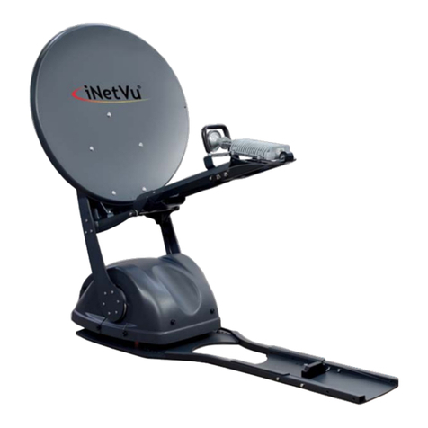
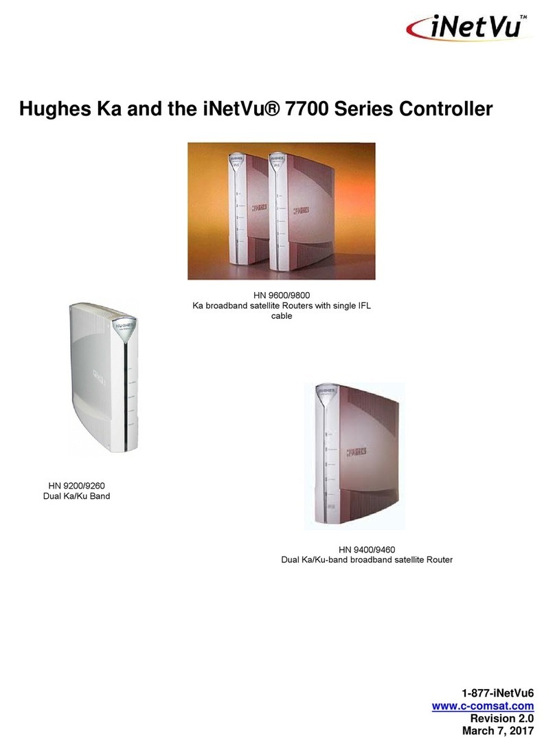
CCOM iNetVu 1.0 Flyaway User manual

iNetVu®1200/1000 Flyaway User Manual
The iNetVu®brand and logo are registered trademarks of C-COM Satellite Systems, Inc.
© Copyright 2006 C-COM Satellite Systems, Inc.
1-877-iNetVu6
www.c-comsat.com
Revision 020
March 22, 2012

C-COM Satellite Systems Inc. Page 2 of 38
iNetVu® Flyaway User Manual
This page is intentionally left blank.

C-COM Satellite Systems Inc. Page 3 of 38
Copyright © 2008. All rights reserved. C-COM Satellite Systems Inc.
This document contains information, which is protected by copyright. All rights reserved.
Reproduction, adaptation, or translation without prior written permission is prohibited, except as
followed under the copyright laws.
Both the iNetVu®and C-COM names and logos are registered trademarks of C-COM Satellite
Systems Inc.
Intel®Pentium is a registered trademark of Intel Corporation. Microsoft, Windows, Windows NT
and MapPoint are registered trademarks of Microsoft Corporation.
All other product names mentioned in this manual may be trademarks or registered trademarks of
their respective companies and are the sole property of their respective manufacturers.
iNetVu® Flyaway User Manual

C-COM Satellite Systems Inc. Page 4 of 38
iNetVu® Flyaway User Manual
Table of Contents
1. Introduction..............................................................................................................5
1.1. About This Manual.............................................................................................. 5
1.2. System Overview................................................................................................ 5
2. Physical Outline.......................................................................................................7
3. Assembly and Disassembly....................................................................................8
3.1. Assembly Procedure........................................................................................... 8
3.2. Disassembly Procedure.................................................................................... 15
3.3. Packaging ......................................................................................................... 22
4. System Connectivity..............................................................................................24
4.1. Typical Connection – PC Free.......................................................................... 24
4.2. Network/Web Interface Connection .................................................................. 25
4.3. Typical USB Communication Interface ............................................................. 26
4.4. System Diagram with Splitter............................................................................ 27
4.5. Router Configuration Example.......................................................................... 28
4.6. Modem Independent Setup (Stand Alone) ....................................................... 29
4.7. USING MODEM COM PORT ........................................................................... 30
5. iNetVu®7000 Controller Configuration................................................................31
5.1. Software Initial Configuration and Verification .................................................. 31
6. Appendix.................................................................................................................37
6.1. Appendix 1: Default Limits and Configuration Data Tables .............................. 38
Proprietary Notice: This document contains information that is proprietary and
confidential to C-COM Satellite Systems, Inc., and is intended for internal and or
C-COM Satellite Systems Inc. authorized partners use only. No part of this
document may be copied or reproduced in any way, without prior written
permission of C-COM Satellite Systems, Inc.

C-COM Satellite Systems Inc. Page 5 of 38
1.Introduction
1.1. About This Manual
This manual explains the iNetVu®Flyaway System Installation and Operation. An
electronic version of this manual is included on the iNetVu®CD that came with your
system.
1.2. System Overview
Equipped to work with the iNetVu®7000 Controller, the iNetVu®Flyaway antenna is an
easily assembled, rugged and reliable product for automatic satellite acquisition. This
lightweight antenna is a rapidly deployable unit that is ideal for applications that require
satellite communication over Ku-Band. The Flyaway empowers users with the ability to
stop anywhere there exists satellite coverage and access Internet at broadband speeds.
The 1.2M Flyaway System comes with a protective case that has been designed to be
airline checkable. Without the use of any tools, the Flyaway could be field assembled
and operational in less than 10 minutes by one person.
Fig. 1: iNetVu®1200/1000 Flyaway
iNetVu® Flyaway User Manual

C-COM Satellite Systems Inc. Page 6 of 38
iNetVu® Flyaway User Manual
The iNetVu®Flyaway system offers the following additional capabilities and features:
3-Axes DC motor drive system
Highly reliable linear actuator to control elevation
Satellite acquisition within 5 minutes (under normal operating conditions)
Compatible with any configured satellite over the Ku Band
Fully automatic, software controlled satellite acquisition
Optimized signal reception and transmission
Self-calibrating and tuning after satellite acquisition
Stand Alone – Satellite Acquisition via DVB (modem independent)
Integrated with some of the leading satellite service providers available.
Easily assembled, light-weight carry gear

C-COM Satellite Systems Inc. Page 7 of 38
2.Physical Outline
2-piece
Detachable reflector
Feed Horn
Polarization
Assembly & Motor Feed Arm Struts
Elevation Motor
Feed Arm
Azimuth Motor &
Gear
iNetVu® Flyaway User Manual

C-COM Satellite Systems Inc. Page 8 of 38
3.Assembly and Disassembly
3.1. Assembly Procedure
Support Stand Assembly
1) Unfold the tripod assembly and lock the leg assemblies into place with the T-Handled
threaded knob as pictured below.
2) Unlock the two (2) T-Handled threaded knobs gripping the lock plate above the pivot
location of the lower reflector assembly. Lift the lock plate, and slide the lower
reflector assembly into the pivot as depicted in the figure below.
iNetVu® Flyaway User Manual

C-COM Satellite Systems Inc. Page 9 of 38
3) Push the lock plate towards the lower reflector assembly, and lock the two (2)
threaded knobs.
4) Attach the elevation motor assembly to the tripod assembly by sliding the elevation
bracket between the tripod assembly and the washers of the T-handled threaded
knobs. You may have to loosen the knobs before insertion.
When the elevation bracket is locked into place, tighten the two (2) T-handled
threaded knobs such that the washer firmly grips the bracket to the tripod assembly.
Facing the back of the reflector, the elevation motor should be facing left.
Note: Avoid twisting
the bellows when
handling the elevation
motor assembly.
iNetVu® Flyaway User Manual

C-COM Satellite Systems Inc. Page 10 of 38
5) Lock the elevation motor assembly into place by lining the mounting holes between
the lower reflector assembly and the elevation motor assembly and inserting the
quick release pin as depicted below.
6) Attach the upper reflector assembly to the lower reflector assembly making sure the
dowel pins fit securely in place.
iNetVu® Flyaway User Manual

C-COM Satellite Systems Inc. Page 11 of 38
iNetVu® Flyaway User Manual
) Lock the reflectors together using the three (3) latches on the back and on both sides7
of the reflector.
) Attach the feed arm to the lower reflector by lining the mounting holes between the
8
feed arm and the attachment block of the lower reflector and inserting the pin.

C-COM Satellite Systems Inc. Page 12 of 38
iNetVu® Flyaway User Manual
) Snap the feed arm strut to the feed arm and reflector sides by retracting the spring-9
loaded barrel on the ball socket end fitting and snapping it into place
0) If the polarization assembly is not already attached to the feed arm, attach the
1
feed polarization assembly to the feed arm assembly, and secure it with the T-
Handled threaded knob located on the bottom side of the feedarm.

C-COM Satellite Systems Inc. Page 13 of 38
iNetVu® Flyaway User Manual
1) Connect the RX Cable running through the feedarm to the LNB, and the TX Cable to
1
the BUC.
2) Connect the internal Motor/Sensor cable, as well as the labelled RX, and TX coax
1
cables running through the bottom of the feedarm to their corresponding inputs on
the connector plate labelled “FEEDARM” on the platform.

C-COM Satellite Systems Inc. Page 14 of 38
13) Connect the reflector (inclinometer) and elevation (elevation motor) cables to the
area on the connector plate labelled “REFLECTOR” and “ELEVATION”. The cables
only fit in one direction.
14) Insert the external Motor/Sensor Cable, RX and TX coax cables into the proper
location on the connector plate labelled “CONTROLLER”.
15) Follow the “Installing BUC with the Universal Mounting Clamp kit” for mounting the
BUC onto the mounting plate of the feed arm.
16) See section 4) for controller connectivity based on your desired connection
preferences.
17) Congratulations, you have successfully assembled the iNetVu®Flyaway System!
iNetVu® Flyaway User Manual

C-COM Satellite Systems Inc. Page 15 of 38
3.2. Disassembly Procedure
WARNING: ENSURE THE PLATFORM IS STOWED BEFORE DISASSEMBLY
Disconnecting Cables
1) Disconnect the External Sensor/Motor cable, RX, and TX coax cables from the
connector plate labelled CONTROLLER on the platform.
2) Disconnect the internal Motor/Sensor cable, RX, and TX coax cables from the
connector plate labelled “FEEDARM” on the platform.
iNetVu® Flyaway User Manual

C-COM Satellite Systems Inc. Page 16 of 38
3) Disconnect the cables from the connector plate labelled “REFLECTOR” and
“ELEVATION”
4) Disconnect the RX and TX Coax cables attached to the BUC and LNB
iNetVu® Flyaway User Manual

C-COM Satellite Systems Inc. Page 17 of 38
Polarization and Feed Arm Assembly Removal
5) Detach the two (2) feedarm struts on both ends by retracting the spring-loaded
barrel on the ball socket end fitting and remove.
6) Gently lower the feedarm, and remove the supporting pin to detach the feedarm
from the reflector.
iNetVu® Flyaway User Manual

C-COM Satellite Systems Inc. Page 18 of 38
Reflector and Elevation Motor Assembly Removal
7) Unhook the three (3) latches holding the two-piece reflector together, and detach
the top reflector assembly.
iNetVu® Flyaway User Manual
Latch Locations

C-COM Satellite Systems Inc. Page 19 of 38
8) Remove the Quick Release T-Pin attaching the elevation motor assembly to the
reflector; ensure to hold the lower reflector assembly during removal of the t-pin.
9) Unlock the two (2) T-Handle threaded knobs securing the elevation motor
assembly to the tripod assembly, and slide the elevation bracket out.
Note: Avoid twisting
the bellows covering
the actuator when
handling the
elevation motor
assembly.
iNetVu® Flyaway User Manual

C-COM Satellite Systems Inc. Page 20 of 38
10) Unlock the two (2) T-Handle threaded knobs attaching the reflector to the tripod
assembly. Ensure to hold the bottom reflector assembly while loosening the
knobs.
11) Slide the reflector from under the lock plate, and remove from the base tripod
assembly.
iNetVu® Flyaway User Manual
This manual suits for next models
3
Table of contents
Other CCOM Antenna manuals
Popular Antenna manuals by other brands

Besto
Besto BOWTIE user manual

CommScope
CommScope CMAX-OMF7-43-UWI53 Installation instruction

Shively Labs
Shively Labs 6842 Instruction Manual Installation, Operation, & Maintenance

Hama
Hama 62770 operating instructions

Kathrein
Kathrein HDP 850 GPS instruction manual

Vivax Metrotech
Vivax Metrotech vLoc3 Series user guide