CDI Traxall X200 User manual

MULTIFREQUENCY PIPELINE PIG TRACKING TRANSMITTERS
Models X200/X200T-2AA and X200-3AA
1801 North Juniper Avenue
Broken Arrow, Oklahoma 74012 U.S.A.
+1 (918) 258-6068 worldwide
www.pigging.com
USER GUIDE
TRAXALL
U
ID
E

TRAXALL X200 Series Mulfrequency Transmier User Guide
Page 2 of 32
Informaon in this document is subject to change without noce and
applies only to the version of soware, hardware, or firmware described
on the tle page.
The soware, hardware, and firmware described in this document are
designed, manufactured, and wrien by CDI. The soware and firmware
copyright © 2014, 2015 CDI with all rights reserved.
This document © 2015 CDI. All rights reserved.
Document Number 89-09-0042-00
Manual Revision 14 Oct 2015
The TRAXALL family of transmiers is covered under United States Patent
No. 9172406.
TRAXALL, TRAXALL Remote Control, FieldLink, and Configurator products
are covered under United States Patents
Microsoand Windows are U.S. registered trademarks of Microso
Corporaon.
Google Earth is a service of Google Inc.
Adobe, the Adobe logo, Acrobat, and Reader are either registered
trademarks or trademarks of Adobe Systems Incorporated in the United
States and/or other countries.

TRAXALL X200 Series Mulfrequency Transmier User Guide
Page 3 of 32
CONTENTS
INTRODUCTION......................................................................................5
OVERVIEW...............................................................................................5
GETTING STARTED..................................................................................6
PREPARE TRANSMITTER: POWER .........................................................7
PREPARE TRANSMITTER: CONFIGURATION.......................................13
PLACING TRANSMITTER INTO SERVICE..............................................24
TROUBLESHOOTING.............................................................................26
REMOVING FROM SERVICE.................................................................26
APPENDIX A:TRANSMITTER BEHAVIOR.............................................27
APPENDIX B:SYSTEM SPECIFICATIONS..............................................29
WARRANTY............................................................................................30
CARE,MAINTENANCE,AND SERVICING.............................................31
ABOUT CDI............................................................................................32

WARNING
Any operaon involving work on pipelines containing gases or liquids
under pressure is potenally hazardous. It is necessary, therefore, to
follow correct procedures in the use of this equipment to maintain a
safe working environment.
No person should use this equipment unless fully aware of potenal
hazards of working with pressurized pipelines and trained in the
procedures stated in this manual.
The purchaser of this equipment is responsible for the training
and competence of operators and the manner in which it is used.
Contact CDI immediately should any difficulty arise in the use of
this equipment.
WARNING
Always use cauon when opening any CDI transmier
that has been in a pressurized environment.
It is possible for pressurized liquid or gas to leak into a transmier
and remain there even aer the transmier has been removed from
the pipeline.
Always point the transmier away from yourself or others when
opening a cover or end cap.
TRAXALL X200 Series Mulfrequency Transmier User Guide
Page 4 of 32

TRAXALL X200 Series Mulfrequency Transmier User Guide
Page 5 of 32
INTRODUCTION
This User Guide is designed to instruct you in the funcon, capabilies,
use, and care of CDI X200-Series mulfrequency pig-tracking transmiers.
OVERVIEW
Electromagnec pipeline pig locaon and tracking transmiers
TRAXALL Mul-frequency transmiers operate by eming
electromagnec fields at a very low frequency (between 17 and 32 Hz)
as well as the industry-standard 22 Hz. This makes them safe and reliable
for use in any onshore or offshore environment and any pipeline product
(water, oil, gas, ammonia, carbon dioxide, etc.).
The X200 is a TRAXALL-compable electromagnec pipeline pig-tracking
transmier that offers both programmable frequency and power control
through CDI’s proprietary FieldLink wireless communicaons system.
Frequency Control allows the operator to configure the transmier to one
of TRAXALL’s seven colorized frequencies, or the 22 Hz legacy frequency
for backward compability with CDI’s CD42 receiver or compeve
receivers.
Power Control allows the operator to directly manage a tradeoffbetween
X200 range vs. baery life. For example, you can set output power to
maximum for short runs/long range, or reduce output power for long
runs/long baery life.
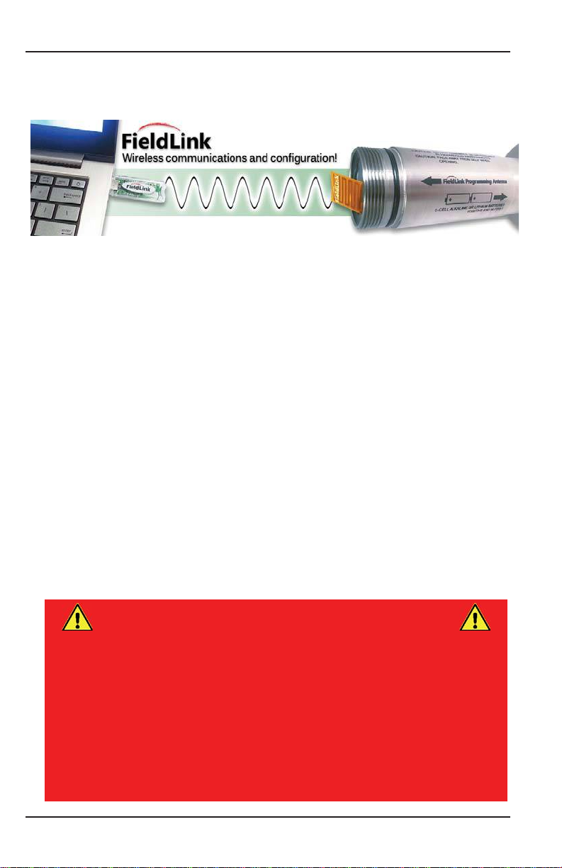
FieldLink is CDI’s proprietary wireless communicaons network. Each X200
transmier comes with a built-in radio frequency antenna. By connecng
a supplied radio frequency USB key, any Windows PC or laptop can be used
to configure the X200.

WARNING
When installing baeries, replace all baeries at the same me.
When replacing baeries, use baeries from the same
package or manufacturing batch whenever possible.
Do not mix alkaline and lithium baeries in the same device.
Always observe correct polarity when installing baeries.
(Polarity is provided on each transmier case.)
TRAXALL X200 Series Mulfrequency Transmier User Guide
Page 6 of 32
Configurator
Configurator is a Windows applicaon that will let you customize
frequency, pulse rate, and output power of your transmiers via FieldLink
wireless communicaon.
Requirements:
• PC or laptop computer with Windows® 7 or 8 (32-bit or 64-bit]
• Configurator soware*
• FieldLink USB device**
• Adobe® Reader® is required to access PDF documents
* Available download from CDI website
** Supplied by CDI
GETTING STARTED
Your transmier requires lile in the way of preparaon. Simply install
fresh baeries and then run Configurator to set transmission signal or
power performance, and your transmier is ready for a pigging run.

TRAXALL X200 Series Mulfrequency Transmier User Guide
Page 7 of 32
PREPARE TRANSMITTER: POWER
End Caps
All CDI transmiers have a knurled threaded cap on each end. To prepare
the X200 for operaon you will need to momentarily remove these caps
to access the baeries and configuraon antenna. Observe nomenclature
on transmier case to determine correct cap, baery quanty, and baery
polarity. Baery and antenna end caps are not interchangeable (antenna
caps are le-hand threaded) but removal and replacement procedures are
similar.
The X200 is available in 2AA and 3AA versions. They differ in performance,
case dimensions (length) and number of baeries required, but
configuraon and baery installaon procedures are essenally the same
for all versions.
Always observe these precauons before removing any transmier
end cap:
Ensure immediate environment is free of explosive gases, liquids, or
other substances.
Use cauon when opening any CDI transmier that has been in
a pressurized environment.
It is possible for pressurized liquid or gas to leak into a transmier
and remain there even aer the transmier has been removed from
the pipeline. For this reason, always point the transmier away from
yourself or others when opening a cover or end cap.
As it is possible for liquids to be present within cap threads, point
transmier downward to drain liquid out of and away from transmier
components or baeries.
rsions.
ANTENNA CAP BATTERY CAP

TRAXALL X200 Series Mulfrequency Transmier User Guide
Page 8 of 32
Remove Baery Cap
Unscrew baery cap by turning counter-clockwise (CCW).
Load Baeries
X200 Series transmiers are powered by
AA alkaline baeries.
NOTE: It is good pracce to always install fresh baeries
before deploying any pipeline pigging device.
NOTE: Transmiers have no “ON/OFF” switch, but are
acvated when baeries are installed and baery cap is
replaced. Therefore, install baeries only when you are about to
configure transmier or beginning a pig run.

TRAXALL X200 Series Mulfrequency Transmier User Guide
Page 9 of 32
All baeries are to be inserted posive (+) end first as shown:
• X200-2AA: Insert two (2) AA baeries
• X200-3AA: Insert three (3) AA baeries
Baery quanty and polarity are marked on each transmier case:
Replacing cap (see following pages) completes the baery circuit and
acvates the transmier.
§
+
+
+
AA CELL ALKALINE OR LITHIUM BATTERIES
POSITIVE END FIRST
§
+
+
AA CELL ALKALINE OR LITHIUM BATTERIES
POSITIVE END FIRST
A baeries
p
v
e
(+
)
en
d
fi
rs
t
as
s
ho
wn
:
•
X2
00-2AA:
Insert two (2) AA baerie
s
•
X2
X2
X2
X2
X2
00-3AA
:
Insert three (3) AA ba
er
ie
s

TRAXALL X200 Series Mulfrequency Transmier User Guide
Page 10 of 32
Replace Baery Cap
Inspect Threads
Before replacing cap, inspect cap threads, transmier case threads, and
O-ring groove.
All threads must be free of
• dents
• deformies
• ruptures
• nicks
• scratches
• dirt
• foreign objects
or anything else that might interfere with a proper seal.
O-RING GROOVE

TRAXALL X200 Series Mulfrequency Transmier User Guide
Page 11 of 32
Inspect O-Rings
Ensure O-ring is serviceable.
A brile and/or deformed O-ring may
not properly seal.
If in doubt, replace it.*
Lubricate O-ring with a light coang of high-temperature grease
(such as Dow Corning MOLYKOTE® 44)
Carefully replace O-ring over threads
and onto its groove.
* Available from CDI (see pg. 29)
C
orni
ng
M
OLYKOTE® 44
)
s

TRAXALL X200 Series Mulfrequency Transmier User Guide
Page 12 of 32
Reinstall Cap
Screw baery cap onto transmier.
Do not over torque. Hand ghtening is sufficient as long as cap is
sufficiently ghtened against rubber O-ring to maintain a seal.
Replacing cap completes the baery circuit and acvates the transmier.
Transmier will remain energized unl baery cap is removed.

TRAXALL X200 Series Mulfrequency Transmier User Guide
Page 13 of 32
PREPARE TRANSMITTER: CONFIGURATION
You will need to have your transmier powered and antenna cap removed
to run Configurator.
Once transmier is configured, the configuraon sengs are stored in the
transmier flash memory and you may power down by removing baeries
unl you are ready to place the transmier into service.
Remove Antenna Cap
Unscrew and carefully remove the antenna cap.
WARNING: Do not
aempt to unfold
or otherwise handle the
flexible antenna.
NOTE: Transmier antenna end caps marked as shown have
LEFT-HAND threads. Turn CLOCKWISE to remove.

TRAXALL X200 Series Mulfrequency Transmier User Guide
Page 14 of 32
Launch Configurator
Use Configurator If you wish to customize frequency, pulse rate, and/or
output power of your transmier.
Launch Configurator by clicking the icon on your PC desktop.

TRAXALL X200 Series Mulfrequency Transmier User Guide
Page 15 of 32
The inial Configurator window will appear as shown here. Transmier,
Transmier Family, Signal Strength, and other fields will be blank or
indicate “N/A” unl communicaon with a transmier is established.
TRANSMITTER SIGNAL
STRENGTH
TRANSMITTER
FAMILY
FAM
FAM
R
SI
I
T
SI
ST
PULSE
PROGRAMMING
TRANSMITTER
CONFIGURATION

TRAXALL X200 Series Mulfrequency Transmier User Guide
Page 16 of 32
AcƟvate FieldLink
FieldLink is CDI’s proprietary wireless PC-to-
transmier communicaons network you will
use to program your transmier.
Insert the FieldLink device* into
a USB port on your pc.
* also known as a flash drive, memory sck, or
“dongle”
A red LED on the device will flash every three
seconds, indicang the device is seeking
to establish a communicaon link with
a transmier.
Select BaƩery Chemistry
When Configurator detects a transmier, it may ask you if the transmier is
powered by Alkaline or Lithium baeries. Click the appropriate buon and
then click “OK” to confirm.

TRAXALL X200 Series Mulfrequency Transmier User Guide
Page 17 of 32
Re-establishing FieldLink CommunicaƟon
If FieldLink communicaon “mes out” or
is otherwise disrupted, this message will
appear.
Should this occur, restart Configurator
by momentarily removing and replacing
baery cap to cycle transmier power.
If you are sll unable to establish communicaon, you may need to
replace baeries.
NOTE: When baeries and baery cap are in place
• The transmier itself will be acvated and will stay acve for
the life of the baery. Removal of baery cap will terminate all
transmier funcon.
• FieldLink will be acvated and for the next five minutes will seek
to establish a communicaon link (see below).

TRAXALL X200 Series Mulfrequency Transmier User Guide
Page 18 of 32
MENU
OPTIONS
TOOL
BAR
TRANSMITTER SIGNAL
STRENGTH
SAVE
MANUAL
REFRESH TRANSMITTER
FAMILY
H
S
S
FAM
FAM
L
R
L
R
R
R
S
S
S
S
S

TRAXALL X200 Series Mulfrequency Transmier User Guide
Page 19 of 32
MENU OPTIONS
File
Exit
Closes the Configurator applicaon
View
Status Bar
Check/uncheck to show
Tool Bar
Check/uncheck to show
USB
Connect/Disconnect
Controls communicaon with FieldLink flash drive
Update Firmware*
Places FieldLink device into update mode
Reset USB Device
Returns FieldLink device to normal operaon
Help
Configurator Help
Opens a PDF version of this Quick-Start Guide
About Configurator
Soware Version and Build informaon
TOOL BAR
Connect/Disconnect
Controls communicaon from FieldLink flash drive
Update Firmware*
Places FieldLink flash drive into update mode
TRANSMITTER INDICATOR
Auto-populated with transmier informaon
TRANSMITTER FAMILY
Indicates X100, X200, X300, or X400
MANUAL REFRESH
Configurator automacally refreshes every four seconds
SIGNAL STRENGTH
Indicates current transmier signal strength
SAVE
Saves configuraon sengs to transmier
* Firmware updates are to be performed only at the direcon of CDI Technical Support

TRAXALL X200 Series Mulfrequency Transmier User Guide
Page 20 of 32
TRANSMITTER
BEHAVIOR
SAVE
R
R
R
R
S
E
S
AV
PULSE
PROGRAMMING
TRANSMITTER
CONFIGURATION
STATUS
BAR
S
R
S
R
This manual suits for next models
10
Table of contents
Other CDI Transmitter manuals