manuals.online logo
Brands
  1. Home
  2. •
  3. Brands
  4. •
  5. Jamara
  6. •
  7. Transmitter
  8. •
  9. Jamara CCX Lipo User manual

Jamara CCX Lipo User manual

IT - Istruzioni per l’uso
GB - Instruction
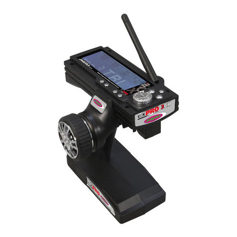
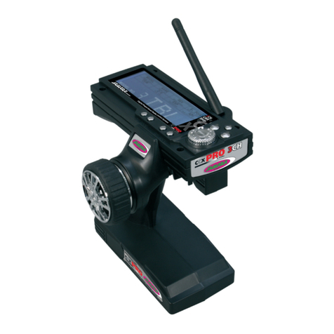
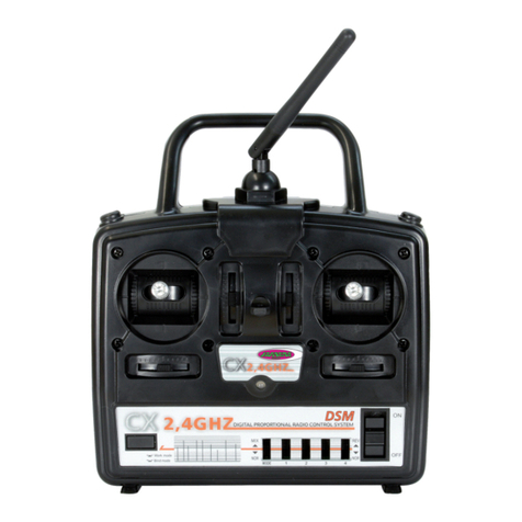
CCX Lipo 2,4 GHz 3 CH
Trasmittente | Transmitter
No. 061201
15/1644/20
IT - Indicazioni generali
L’azienda JAMARA e. K. non risponderà dei danni causati al prodotto o dal prodotto, qualora esse
derivino dall‘uso o dall‘utilizzo non conforme. Il cliente sarà pienamente responsabile del cor-
retto uso e del corretto utilizzo. Ciò riguarda, in particolare, il montaggio, il processo di ricarica,
l‘applicazione, la scelta dell‘area di applicazione. A tal ne sarà necessario prendere conoscenza
delle istruzioni per l’uso, contenenti informazioni e avvertenze importanti.
GB - General information
JAMARA e.K. is not liable for any damage caused to the product itself or by it, if this is due to impro-
per operation or handling errors. The customer alone bears the full responsibility for the proper use
and handling, including in particular, assembling, charging and using the model, and selecting the
area in which to use it. Please refer to the operating and user instructions, which contain important
information and warnings.
IT - Dichiarazione di conformità
Con la presente JAMARA e.K. dichiara che il prodotto “CCX Lipo 2,4 GHz,
No. 061201“ è conforme alla Direttiva 2014/53/UE, 2011/65/UE.
Il testo integrale della dichiarazione di conformità UE è disponibile al seguente indiriz-
zo Internet: www.jamara-shop.com/Conformity
GB - Certicate of Conformity
Hereby JAMARA e.K. declares that the product “CCX Lipo 2,4 GHz, No. 061201“ complies with
Directive 2014/53/EU, 2011/65/EU.
The full text of the EU Declaration of Conformity is available at the following Internet address:
www.jamara-shop.com/Conformity
Contenuto del kit:
• Trasmittente
• Ricevente
• Batteria LiPo 3,7 V 800 mAh 2,96 Wh,
• Cavo di ricarica USB
• Istruzioni
Accessori richiesti:
8 x batterie AA Cod. 140267 (4 pz.)
Caratteristiche:
• 3 canali
• Sistema 2,4 GHz
• Dual Rate
• Servorevers (Gas/sterzo)
• Regolamento posizione neutrale servo
• Modulazione AFHDS
• Adatto per auto, barche
• Alimentazione 3,7 V
• Sicurezza di sottotensione
• Presa di caricamento USB
• Fail-Safe al ricevente
• Peso 270 g
• Dimensioni 156 x 223 x 94 mm
Ricevente CCX Pro 2,4 GHz
Cod. 061185
Frequenza 2,4 GHz
Modulazione AFHDS
Tensione di operazione 4,8 - 7,4 V DC
Modulazione servo 10 Bit (1024 Passi)
Dimensioni 37 x 22 x 13 mm
Peso 7,6 g
Box contents:
• Transmitter
• Receiver
• Battery LiPo 3,7 V 800 mAh 2,96Wh
• USB charging cable
• Instruction
Recommended Accessories
8 x AA Batteries Ord. No. 140267 (4 pieces)
Features:
• 3 channel
• 2,4 GHz System
• Dual Rate
• Servo reverse (Gas/steering)
• Adjustment of servo centre
• Modulation AFHDS
• Model types Car, boat
• Operating range 3,7 V
• Low-Voltage warning
• Charging socket USB
• Fail Safe on receiver
• Weight 270 g
• Size 156 x 223 x 94 mm
Receiver CCX Pro 2,4 GHz
Ord.No. 061185
Technical data:
Frequency 2,4 GHz
Modulation AFHDS
Operating voltage 4,8 - 7,4 V DC
Servo resolution 10 Bit (1024 steps)
Dimensions 37 x 22 x 13 mm
Weight 7,6 g
Questo modello non é un giocattolo!
Prima di avviare il modello, leggere attentamente tutte le istruzioni per l’uso.
Attenzione! Leggere completamente le avvertenze / istruzioni di sicurezza,
questi sono per la vostra sicurezza può prevenire incidenti / infortuni.
For model building only - Not a toy!
Read the complete instructions and security instructions carefully before using the
model.
Caution! Please fully and carefully read warnings/ safety instructions.
These are for our own security and can avoid accidents/injuries.
Rispettate inoltre le norme seguenti:
• Prima di accendere la vostra radio controllate che lo stick del gas sia al minimot.
• Assicurarsi che il binding della trasmittente e della ricevente siano e󰀨ettuati in modo corretto.
• Accendete primable trasmittente e poi la ricevente.
• Agite al contrario per spegnere.
• Prima di andare in volo fate sempre una prova di portata in distanza con il modello a terra e
l‘antenna chiusa.
• Non mettere in pericolo persone o animali.
• Utilizzare il sistema o il modello solo per essere controllati su un terreno adatto.
• Non usare la trasmittente con pioggia, vento forte oppure temporali.
• Se per un periodo più lungo non usata la trasmittente, togliete le batterie.
Following should be strictly adhered to:
• Before Switching on the system ensure that throttle stick is in the o󰀨 position.
• Check that the transmitter and receiver are compatible and bonded to one another.
• Always switch the transmitter on  rst and then the receiver.
• Always switch the receiver o󰀨  rst and then the transmitter .
• Complete a full range and function test before every take-o󰀨 .
• Never over- y people and do not allow your model to endanger people or animals.
• Do not  y near to over-head cables, buildings or air elds.
• The system must not be operated in rain, or thunder storms.
• If you do not intend to use the transmitter for a long period, remove the batteries.
Frequency bands: 2.4 GHz Frequency range: 2405,5 – 2475,0 MHz EIRP: < 40 mW (max. power transmitted)

2
IT - Carica accumulatori
Se si inseriscono nelle trasmettente accumulatori NiCd o NiMH, accertarsi prima dell‘uso che le celle
siano completamente cariche. A causa dell’auto-scarica, è necessario ricaricare le batterie prima di
ogni utilizzo. Seguire sempre le istruzioni della fabbrica produttrice delle celle.
Assicurarsi di mettere un caricabatterie idoneo. Lasciarsi consigliare dal proprio rivenditore. Dopo
aver caricato completamente le celle, scollegare la trasmittente staccando la spina dalla presa di
ricarica e togliere la spina del caricabatterie dalla presa di corrente.
Rimuovere le batterie della trasmittente e del modello quando non si utilizzano per periodi prolunga-
ti. Caricare la batteria della trasmettente, procedendo come segue:
1. Inserire le batterie con la polarità corretta.
2. Collegare la spina del caricatore a una presa a muro.
3. Inserire il caricatore nella presa di ricarica del trasmettitore.
4. Staccare il caricabatterie dalla trasmittente quando le celle sono completamente cariche.
GB - Charging the battery
Ensure that the cells are fully charged before using the system. Please be aware that due to the
self-discharge characteristics of this type of cells that they should always be fully charged prior to
use. Please refer to the battery manufacturers recommendations regarding charging current etc.
Use only a high quality charging cable which is suitable for this type of cells. For further information
please contact your local dealer. Once charging is complete, always disconnect the batteries from
the charger.
Remove the batterie from the model and transmitter if you do not intend to operate it for a longer
period of time. To charge teh transmitter batteries please proceed as follows:
1. Fit the batterie observing the correct polarity.
2. Connect the charging cable with a suitable USB port.
3. Connect the charging cable to the transmitter.
4. Unplug the charger as soon as the batteries are full.
IT
Con una sincronia di pulsanti, interruttori e display LCD, la trasmettente CCX-LiPo 2.4 GHz, può
essere programmata rapidamente e con facilità. Tutti i canali possono essere trimmati, inoltre è
possibile invertire la direzione. In più, vi sono a disposizione le funzioni, Dual-Rate, EXPO e ABS.
Una LED indica lo stato di carica della alimentazione del trasmittente.
GB
Thanks to the logical and well thought out lay-out of the Programming Panel and the positioning
of the switches and LEDs the CCX Lipo 2,4GHz 3CH transmitter can be quickly and simply pro-
grammed. Both channels can be trimmed and the direction changed. Furthermore the transmitter is
equipped with a Dual Rate system and a red LED indicates the state of the battery charge.
IT - Controlli
Vista laterale destra
1. Scatola di programmazione
2. Antenna 2.4 GHz
3. Volante
4. Leva del gas
5. Vano Batterie
6. 3 canale
Settore di programmazione
7. Direzione trim
8. Direzione Reverse
9. Power LED
10. Interruttore on /o󰀨
11. Gas Reverse
12. Pulsante collegamento Binde
13. Gas Trim
14. Power Check
15. Dual Rate
IT - Vista laterale
G. Presa di carica
GB - Rear Side
G. Charge Socket
DE - Controls
Side View
1. Programming Box
2. 2,4 GHz Antenna
3. Steering Wheel
4. Throttle Lever
5. Battery Hatch
6. 3-Channel
Programming Panel
7. Steering Trim
8. Steering Reverse
9. Power LED
10. ON/OFF Switch
11. Throttle Reverse
12. Binding Button
13. Throttle Trim
14. Power Check
15. Dual Rate
1
7
8
9
10
11
12
13
14
15
2
3
4
5
6
G
33
IT - Installazione della ricevente
Attenzione!
Assicurarsi che la polartità sia corretta, quando si collega il cavo (+ & - Pol),altrimenti puo succedere
che la ricevente ha un corto circuito.
GB - Connecting to the receiver
Warning!
To avoid any short-circuit in your receiver, please make sure to connect the cables with correct
polarity in mind.
IT - Antenna
Collegare l‘antenna verticale 2,4 GHz, come illustrato nella gura adiacente. Non si può, tuttavia,
montare l‘antenna su oggetti metallici, il raggio d’azione si ridurrebbe notevolmente.
GB - Antenna
Mount the 2.4 GHz antenna vertically as shown in the diagram. Do not allow any metal object to
come into contact with the antenna or to shield it as this will reduce the range.
Modello con motore elettrico
Wiring diagram for electric models
Interruttore
Switch
Interruttore
Switch Batteria
Battery Pack
Servo Gas
Throttle Servo
Servo direzionale
Steering Servo
Regolatore
ESC
Servo direzionale
Steering
Canale 2
2CH
Ricevente
Receiver
Ricevente
Receiver
Batteria
Battery Pack
Motore
Modello con motore a combustione
Wiring diagram for I/C engine models
Ricevente
Receiver
2,4 GHz Antenna
2,4 GHz Antenna
Fail Safe LED
CH2
Batteria / Battery
CH1
CH3/Bind
4
IT - Allacciare la trasmittente alla ricevente
In un moderno sistema di 2,4 GHz, è indispensabile che la trasmittente e la ricevente vengano
connesse insieme a bordo del modello. La ricevente accetta quindi solo i segnali della trasmittente.
Se per qualsiasi motivo si dovesse e󰀨ettuare un nuovo allacciamento “connessione”, eseguire le
seguenti operazioni:
A. Sostituire nella trasmettente le batterie scariche con altre cariche o nuove. Lasciare spenta la
trasmettente.
B. Inserire la spina di accoppiamento in dotazione nell’uscita del canale 3.
C. Accendere la ricevente, collegando le batterie alla stessa ricevente. Il LED della ricevente
inizia a lampeggiare, indicando che la ricevente è pronta in modus “connessione”.
D. Tenere premuto il pulsante di connessione sulla trasmittente, mentre si accende la stessa.
E. Il LED della ricevente inizia a lampeggiare, indicando che la ricevente è pronta in modus
“connessione”.
F. Rilasciare il pulsante di connessione della trasmettente e rimuovere la spina di connessione
nella ricevente. Spegnere la ricevente e la trasmittente.
G. Ora spegnere il trasmettitore. L‘impianto è in la prossima volta che si accende legato.
H. Installare correttamente tutti gli accessori e controllare con molta attenzione.
I. Se la funzione non avesse successo, ripetere la procedura di connessione.
L’illustrazione seguente mostra gracamente il processo di connessione e specica gli elementi
da utilizzare.
GB - Binding the receiber to the transmitte
As with all modern 2.4GHz R/C systems the receiver must be bound to the transmitter to ensure that
the receiver will only react to signals from that transmitter. If you wish to re-bind the receiver with the
transmitter please proceed as follows:
A. Ensure that the transmitter is tted with fully charged batterie and leave the transmitter o󰀨.
B. Plug the binding plug (included) into the channel 3 socket on the receiver.
C. Switch the receiver system on by connecting the battery or turn in a BEC operating on a controller
to control. The receiver LED will begin to ash indicating that the receiver is in bonding mode.
D. Press and hold down the binding button on the transmitter whilst switching it on.
E. The transmitter will begin to  ash indicating that the receiver is in bonding mode.
F. Release the binding button on the transmitter and disconnect the receiver from the battery or turn
o󰀨 the controller. Release the binding plug from the receiver.
G. Switch of the transmitter. and remove the binding wire. The system be bound at the next start ..
H. Install all properly and check anything very precisely.
I. If the receiver fails to bond or does not function after bonding repeat the above procedure until a
successful bonding is achieved.
The following diagrams illustrate the bonding process and show the locations of the relevant com-
ponents.
IT - Fail Safe
Programmazione del gruppo integrato di FailSafe.
1. Descrizione della Funzione
L’unità FailSafe è concepita principalmente per l‘utilizzo sulle imbarcazioni e sui veicoli. Serve per
evitare la perdita del modello, determinando la chiusura del gas, nell’eventuale assenza di segnale.
Se la ricevente perde il segnale della trasmittente, il servo del gas o regolatore di velocità ritorna
automaticamente sulla posizione programmata inizialmente.
2. Impostazione
a. Accendere la trasmittente
b. Accendere la ricevente. Il segnale LED lampeggia continuamente
e indica che la ricevente è pronta.
c. Spostare sul trasmettitore la leva dell‘acceleratore nella posizione di freno, o zona spento nel
regolatore di velocità. Tenere la leva del gas su questa zona.
d. Premere il pulsante Imposta sul ricevitore. Il segnale LED lampeggia per 3 secondi
(vedi illustrazione a sinistra).
e. L‘impostazione è salvata e si può portare la leva dell’acceleratore in posizione neutra.
3. Prova delle impostazioni
a. Accendere la trasmittente.
b. Accendere la ricevente.
c. Spegnere la trasmittente.
d. Ora la ricevente perde il segnale e conduce il servo del canale gas o il regolatore di velocità
sulla posizione in precedenza programmata.
e. Seguire la procedura descritta sopra, il processo FailSafe funziona correttamente.
GB - Fail Safe
Programming of the integrated FailSafe unit.
1. Function Description
The function of protection of losing control is mainly for r/c boats and cars and keeps them away from
damage through throttle channel. When the receiver is out of control signal, the receiver of throttle
will automatically return to the initial position which set up before starting to avoid the error action.
2. Setting
a. Turn on the transmitter
b. Turn on the receiver. The signal LED will light continuously and indicates that the receiver is
ready.
c. Move the throttle lever on the transmitter in the braking or outlet position. Hold the throttle lever
in this position.
d. Press the Setup button on the receiver. The signal LED ashes for 3 seconds (see left).
e. The setting is saved and you can bring back the throttle into neutral position.
3. Testing the settings
a. Turn on the transmitter.
b. Turn on the receiver.
c. Turn o󰀨 the transmitter.
d. The receiver will now lose the signal and drives the servo or the speed control on the gas channel
to the previously programmed position.
e. If these steps work, you have set the FailSafe.
Pulsante
collegamento
Binding button
Spina allacciare
Binding Plug
LED
Fail Save
5
IT - Procedure di accensione
1. Mettere insieme tutti gli elementi.
2. Accendere la trasmittente.
3. Collegare la batteria alla riceven-
te.
4. Vericare che il LED sul ricevitore
sia stabilmente acceso.
5. Il sistema è acceso e può essere
utilizzato.
IT - Sequenza di spegnimento
1. Disinserire la batteria dalla rice-
vente
2. Spegnere la trasmittente
IT - Controllo del modello
Grazie a questa funzione si determina il controllo sullo sterzo. Con una rotazione del volante, le ruo-
te dell‘asse anteriore devono sterzare nella direzione desiderata. Se il volante gira a destra, come
illustrato nella foto sopra, le ruote devono girare a destra. Nella foto a lato si illustra una sterzata
per curvare a sinistra.
Con il relativo interruttore (6) nell’area di programmazione si può, se necessario, invertire la direzi-
one. Per un controllo più sensibile, con il tasto Dual-Rate, si può scegliere una funzione Dual-Rate
programmata in precedenza. Una rotazione del volante vicino alla posizione neutra, comporta una
reazione relativamente piccola. La corsa del servo, tuttavia, è completamente disponibile, ad esem-
pio, per manovre di virata.
GB - Operating the model
This function is used to steer the model and turning the steering wheel will make the models wheels
to turn in the relevant direction. Turning the wheel to the right will make the models wheels turn to
right when viewed from above as illustrated. Moving the wheel to the left will cause the wheels to
turn to the left.
By operating the relevant switch (6) on the programming panel the direction in which the steering
moves can be reversed if required. In addition, the transmitter is equipped with a Dual Rate function.
When this function is activated the wheels of the model will move less relative to the movement of
the transmitters steering wheel around the middle position. This will allow the model to be steered
with more precision however if this function is used the total throw will still be available
for tight cornering when the steering wheel is moved to the end of it’s range.
GB - Switch on
1. Plug in all of the components.
2. Switch the transmitter on.
3. Connect the receiver battery to the
receiver.
4. Check that the LEDs on both the
transmitter and the receiver illuminate
solidly.
5. The system is now correctly switch
on and operating and can now safely
be used.
GB - Switching o󰀨
1. Disconnect the receiver battery
2. Switch o󰀨 the transmitter
Accendere
Switching On
1. Accendere la
trasmittente
1. Switch the
transmitter on
2. Accendere la
ricevente
2. Switch the
receiver on
1. Spegnere il
ricevitore
1. Switch o󰀨
the receiver
2. Spegnere la
trasmittente
2. Switch o󰀨 the
transmitter
Spegnere
Switching O󰀨
Sterzo
Steering
6
Controllo del gas
Trottle Lever
IT - Controllo del gas
Con questa funzione, possono essere controllati: il movimento in avanti e indietro, e la velocità. Se
il sensore di controllo viene tirato indietro, il veicolo si sposta in avanti, come illustrato nell‘immagine
adiacente.
Se il sensore di controllo della trasmettente viene premuto in avanti, come illustrato nella foto qui
sotto, da prima il veicolo frena, e poi va all‘indietro. Condizione per questo comando, tuttavia, è un
veicolo a trazione elettrica, con un determinato regolatore di velocità.
GB - Trottle Lever
This function is used to control the models speed both forwards and in reverse as shown in the
illustration to the left. If the lever is pulled back towards the transmitter grip the model will accelerate
forwards.
If the lever is pushed away from the transmitter grip the model will rst brake and then accelerate
in reverse. This is providing that the model is tted with a Speed Controller which supports these
functions.
IT - Passare alla terzo canale:
Posizionare un servo del terzo canale in posizione alta a sinistra / destra.
GB - Auxiliary Channel 3 Switch:
Controls auxiliary channel 3 high and low servo travel.
CH 3
7
IT - Centro assistenza GB - Service centre
Reitter Modellbau Versand
Patricia Reitter
Degerfeldstrasse 11
72461 Albstadt
Tel 07432 9802700
Fax 07432 2009594
Mail [email protected]
Web www.modellbauversand.de
Modellbau-Zentral
Peter Hofer
Bresteneggstrasse 2
CH -6460 Altdorf,
Tel. +41 794296225
Fax +41 418700213
[email protected]
www.modellbau-zentral.ch
PenTec s.r.o.
distributor Jamara for Czech Republic and Slovakia
Veleslavínská 30/19
CZ -162 00 Praha 6
Tel +420 235 364 664
Mobil. +420 739 075 380
Mail servis@topdrony.cz
Web www.topdrony.cz
Bay-Tec
Martin Schaaf
Am Bahndamm 6
86650 Wemding
Tel 07151 5002192
Fax 07151 5002193
Mail [email protected]
Web www.bay-tec.de
DE DE
JAMARA e.K.
Manuel Natterer
Am Lauerbühl 5
DE-88317 Aichstetten
Tel +49 (0) 75 65/94 12-0
Fax +49 (0) 75 65/94 12-23
Mail [email protected]
Web www.jamara.com EU
CH CZ
JAMARA e.K.
Inh. Manuel Natterer
Am Lauerbühl 5 - DE-88317 Aichstetten
Tel. +49 (0) 75 65/94 12-0 - Fax +49 (0) 75 65/94 12-23
[email protected] ●www.jamara.com
Service - Tel. +49 (0) 75 65/94 12-777
kundenservice@ jamara.com
Irrtum und technische Änderungen vorbehalten. Copyright JAMARA e.K. 2021
Kopie und Nachdruck, auch auszugsweise, nur mit Genehmigung von JAMARA e.K.
All rights reserved. Copyright JAMARA e.K. 2021
Copying or reproduction in whole or part, only with the expressed permission of JAMARA e.K.
Fordern Sie noch Heute den aktuellen Hauptkatalog mit
unserem gesamten Warensortiment an.
Name _______________________________
Vorname _______________________________
Straße _______________________________
Wohnort _______________________________
Telefon _______________________________
E-mail _______________________________
Bitte senden Sie den Katalog für mich an folgenden
Fachhändler:
Ihr Fachhändler
_______________________________________________
_______________________________________________
_______________________________________________
_______________________________________________
Der Katalog wird mit der nächsten Bestellung des Händ-
lers auf Ihren Namen mitgeliefert.
Order the current catalogue with our complete
assortment of modelling goods today.
Name _______________________________
First name _______________________________
Street _______________________________
City _______________________________
Phone _______________________________
E-mail _______________________________
Please send the catalogue to the following specialist
dealer:
Your dealer
_______________________________________________
_______________________________________________
_______________________________________________
_______________________________________________
We will include a catalogue for your attention with the
next order placed by your dealer.
Gutschein Coupon

Other manuals for CCX Lipo

3

This manual suits for next models

1

Other Jamara Transmitter manuals

Jamara CCX Pro User manual

Jamara

Jamara CCX Pro User manual

Jamara Compa 2,4 GHz User manual

Jamara

Jamara Compa 2,4 GHz User manual

Jamara FCX6 Pro Tel User manual

Jamara

Jamara FCX6 Pro Tel User manual

Jamara Compa X3 Evo User manual

Jamara

Jamara Compa X3 Evo User manual

Jamara SCX 2,4 GHz User manual

Jamara

Jamara SCX 2,4 GHz User manual

Jamara Compa X3 Evo User manual

Jamara

Jamara Compa X3 Evo User manual

Jamara FCX6 Pro Tel User manual

Jamara

Jamara FCX6 Pro Tel User manual

Jamara CCX Pro 2,4 GHz User manual

Jamara

Jamara CCX Pro 2,4 GHz User manual

Jamara CCX Pro 2,4 GHz User manual

Jamara

Jamara CCX Pro 2,4 GHz User manual

Jamara CCX Pro User manual

Jamara

Jamara CCX Pro User manual

Jamara SCX 2,4 GHz User manual

Jamara

Jamara SCX 2,4 GHz User manual

Jamara Compa User manual

Jamara

Jamara Compa User manual

Jamara CCX Pro User manual

Jamara

Jamara CCX Pro User manual

Jamara FCX6 Pro Tel User manual

Jamara

Jamara FCX6 Pro Tel User manual

Jamara FCX6 Pro Tel User manual

Jamara

Jamara FCX6 Pro Tel User manual

Jamara CCX Lipo 2,4 GHz 3 CH User manual

Jamara

Jamara CCX Lipo 2,4 GHz 3 CH User manual

Jamara FCX6 Pro Tel User manual

Jamara

Jamara FCX6 Pro Tel User manual

Jamara CCX Pro User manual

Jamara

Jamara CCX Pro User manual

Jamara CCX Lipo 2,4 GHz 3 CH User manual

Jamara

Jamara CCX Lipo 2,4 GHz 3 CH User manual

Jamara CCX Pro 2,4 GHz User manual

Jamara

Jamara CCX Pro 2,4 GHz User manual

Jamara CCX Lipo 2,4 GHz 3 CH User manual

Jamara

Jamara CCX Lipo 2,4 GHz 3 CH User manual

Jamara CX 2,4 GHz User manual

Jamara

Jamara CX 2,4 GHz User manual

Jamara FCX6 Pro Tel User manual

Jamara

Jamara FCX6 Pro Tel User manual

Jamara FCX6 Pro Tel User manual

Jamara

Jamara FCX6 Pro Tel User manual

Popular Transmitter manuals by other brands

Sonic Alert HomeAware HA360VPT Installation and setup guide

Sonic Alert

Sonic Alert HomeAware HA360VPT Installation and setup guide

Wyrestorm EX-2UTP-IR-50 user guide

Wyrestorm

Wyrestorm EX-2UTP-IR-50 user guide

T'nB FMCT05B instructions

T'nB

T'nB FMCT05B instructions

One Forall SV1770 Quick installation guide

One Forall

One Forall SV1770 Quick installation guide

Resolution RE108 quick start guide

Resolution

Resolution RE108 quick start guide

Microdigital MDC-i4280C user manual

Microdigital

Microdigital MDC-i4280C user manual

Paradox Magellan DCTXP2 user manual

Paradox

Paradox Magellan DCTXP2 user manual

IMG STAGE LINE TXS-606LT instruction manual

IMG STAGE LINE

IMG STAGE LINE TXS-606LT instruction manual

Camsat VueNet EasyLink user manual

Camsat

Camsat VueNet EasyLink user manual

Black Box InvisaPC quick start guide

Black Box

Black Box InvisaPC quick start guide

Blu Stream Multicast IP250UHD-TX user manual

Blu Stream

Blu Stream Multicast IP250UHD-TX user manual

Tek-Trol TEK-WAVE 4300B quick start guide

Tek-Trol

Tek-Trol TEK-WAVE 4300B quick start guide

HYDACELECTRONIC HLT 2150-R1 operating instructions

HYDACELECTRONIC

HYDACELECTRONIC HLT 2150-R1 operating instructions

smart home SwitchLinc 12080W user manual

smart home

smart home SwitchLinc 12080W user manual

Camsat CAM8h-Multi2/AHD user manual

Camsat

Camsat CAM8h-Multi2/AHD user manual

Black Box CATX Series manual

Black Box

Black Box CATX Series manual

AVPro Edge ConferX AC-CXWP-HDMO-T user manual

AVPro Edge

AVPro Edge ConferX AC-CXWP-HDMO-T user manual

Evikon PluraSens E2218 user manual

Evikon

Evikon PluraSens E2218 user manual

manuals.online logo
manuals.online logoBrands
  • About & Mission
  • Contact us
  • Privacy Policy
  • Terms and Conditions

Copyright 2025 Manuals.Online. All Rights Reserved.