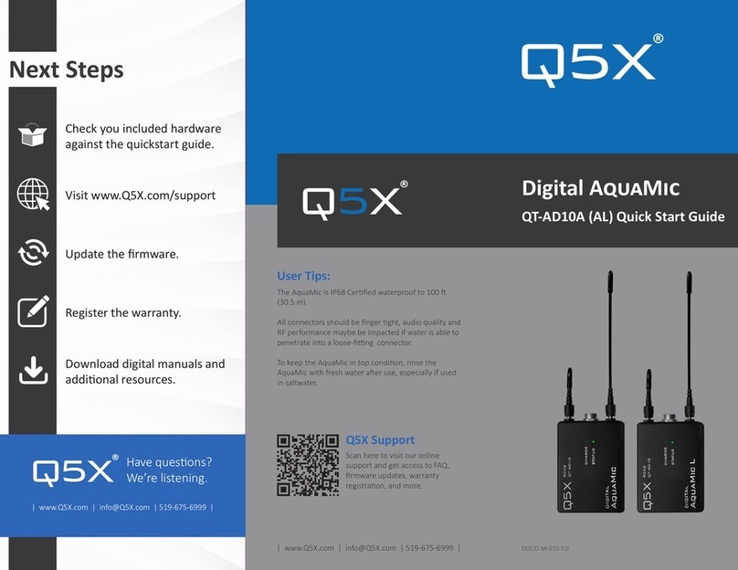
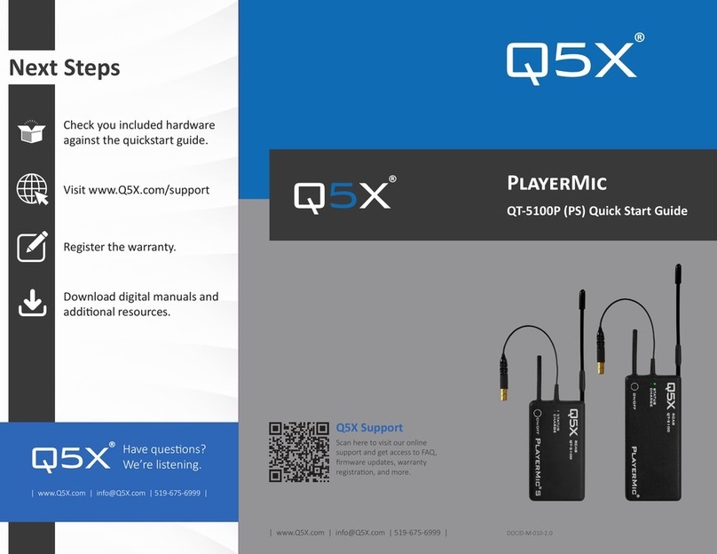
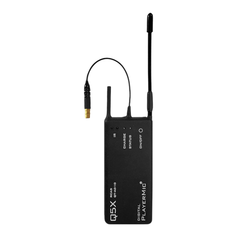
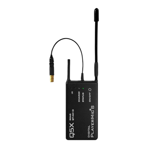
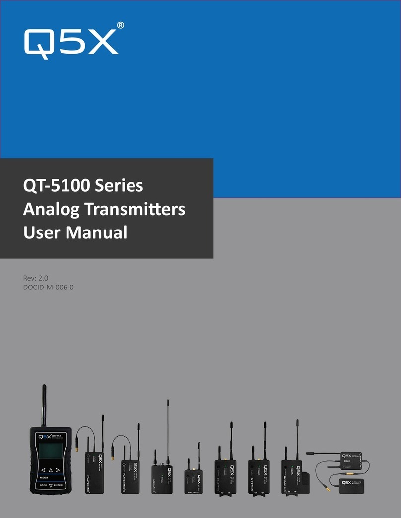
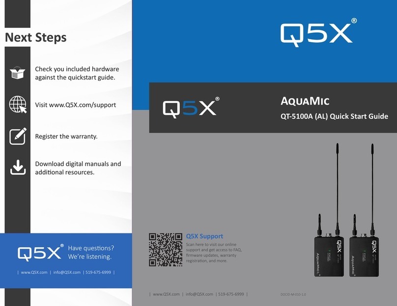
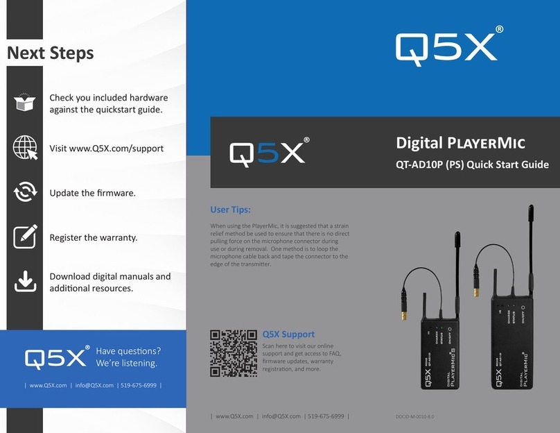
Q5X QT-AD10 Series User manual

USER MANUAL
QT-AD10 SERIES
Axient Digital Transmitters

REGULATORY INFORMATION
FCC Notices:
Information to users:
This device complies with Part 15 of the FCC Rules. Operation is subject to the following two conditions:
1. This device may not cause harmful interference, and
2. This device must accept any interference received, including interference that may cause undesired operation.
This equipment has been tested and found to comply with the limits for a Class B digital device, pursuant to part 15 of the FCC Rules. These limits are designed to provide
reasonable protection against harmful interference in a residential installation. This equipment generates, uses and can radiate radio frequency energy and, if not installed and
used in accordance with the instructions, may cause harmful interference to radio communications. However, there is no guarantee that interference will not occur in a
particular installation. If this equipment does cause harmful interference to radio or television reception, which can be determined by turning the equipment off and on, the user
is encouraged to try to correct the interference by one or more of the following measures:
•Reorient or relocate the receiving antenna.
•Increase the separation between the equipment and receiver.
•Connect the equipment into an outlet on a circuit different from that to which the receiver is connected.
•Consult the dealer or an experienced radio/TV technician for help.
Warnings:
Wireless microphone users shall rely on the white space databases in part 15, Subpart H to determine that their intended operating frequencies are available for unlicensed
wireless microphone operation at the location where they will be used. Wireless microphone users must register with and check a white space database to determine available
channels prior to beginning operation at a given location. A user must re-check the database for available channels if it moves to another location. Changes or modifications not
expressly approved by Quantum5X Systems Inc, could void the user’s authority to operate the equipment. This module has been designed to operate with only the supplied
integrated antenna or the supplied SSMA antenna for the 802.15.4 Radio. Replacing or modifying these antennas is strictly prohibited.
Innovation, Science and Economic Development Canada (ISED)
This device contains license-exempt transmitter(s)/receiver(s) that comply
with Innovation, Science and Economic Development Canada’s license-exempt
RSS(s). Operation is subject to the following two conditions:
1. This device may not cause interference.
2. This device must accept any interference, including interference that
may cause undesired operation of the device.
Approved antenna and connectors:
This radio transmitter IC:4614A-QTAD10A has been approved by Innovation,
Science and Economic Development Canada to operate with the antenna types
listed below, with the maximum permissible gain indicated. Antenna types not
included in this list that have a gain greater than the maximum gain indicated for
any type listed are strictly prohibited for use with this device.
This device operates on a no-interference, no-protection basis. Should the user
seek to obtain protection from other radio services operating in the same TV
bands, a radio license is required. For further details, consult Innovation, Science
and Economic Development Canada’s Client Procedures Circular CPC-2-1-28,
Voluntary Licensing of License-Exempt Wireless Microphones in the TV Bands.
L’émetteur/récepteur exempt de licence contenu dans le présent appareil est
conforme aux CNR d’Innovation, Sciences et Développement économique Canada
applicables aux appareils radio exempts de licence. L’exploitation est autorisée
aux deux conditions suivantes:
1. L’appareil ne doit pas produire de brouillage;
2. L’appareil doit accepter tout brouillage radioélectrique subi, même si
le brouillage est susceptible d’en compromettre le fonctionnement.
Le présent émetteur radio IC:4614A-QTAD10A a été approuvé par Innovation,
Sciences et Développement économique Canada pour fonctionner avec les types
d'antenne énumérés ci dessous et ayant un gain admissible maximal. Les types
d'antenne non inclus dans cette liste, et dont le gain est supérieur au gain
maximal indiqué pour tout type figurant sur la liste, sont strictement interdits
pour l'exploitation de l'émetteur.
Ce dispositif fonctionne selon un régime de non-brouillage et de non-protection.
Si l’utilisateur devait chercher à obtenir une certaine protection contre d’autres
services radio fonctionnant dans les mêmes bandes de télévision, une licence
radio serait requise. Pour en savoir plus, veuillez consulter la Circulaire des
procédures concernant les clients CPC-2-1-28, Délivrance de licences sur une base
volontaire pour les microphones sans fil exempts de licence exploités dans les
bandes de télévision d’Innovation, Sciences et Développement économique
Canada.
Antenna / Connector Type
Manufacturer
Connector Type
Max Gain
¼λ Wire Antenna
Q5X
MHF-4L
UHF 0 dBi, 2.45GHz 2dBi
SSMA ¼λ Whip Antenna
Sam Woo Electronics
MHF-4L - SSMA
UHF 0 dBi, 2.45GHz 2dBi
RF Exposure Compliance
The QT-AD10 module is granted with a modular approval for portable applications. The module is to be used by Quantum5X in their final products without additional FCC/ISED
certification if they meet the certification conditions.
Module Integration into Host End Products
The QT-AD10 module transmitter has been designed by Quantum5X Systems Inc. to be used by Quantum5X as a building block for their wireless audio transmitter products. The
module, as designed, is a standalone unit that is ready for integration into final form factor with the limitation for mobile use as specified in RF Exposure compliance. For proper
usage of the module, the module integrator must ensure that the input power and input audio signal do not exceed the specified limits as outlined in the specification section.
Failure to do so will result in damage to the module. Final product(s) after integration with this module shall be tested to comply with all applicable FCC requirements and
Unintentional radiators (FCC section 15.107, 15.109 and ISED ICES-003) before declaring compliance to Part 15 of the FCC Rules and ISED ICES-003.
The module integrator may not do the following. Failure to comply with these restrictions will result in violation of the FCC certification.
1) Alter, modify or remove the module case.
2) Make changes to the Circuit Card Assembly of the module.
3) Remove, change or alter the integrated UHF antenna or the 802.15.4 antenna.
Labeling of the End Products
The modular transmitter must be equipped with either a permanently affixed label. The modular transmitter must be labeled with its
own FCC identification number, and, if the FCC identification number is not visible when the module is installed inside another device,
then the outside of the device into which the module is installed must also display a label referring to the enclosed module. This
exterior label can use wording such as the following: ‘‘Contains Transmitter Module” or ‘‘Contains “. Any similar wording that expresses
the same meaning may be used. Sample labels, that must be used for the module and the product, are shown on the right.

TABLE OF CONTENTS
___________________________________________________________________________________
1.0 INTRODUCTION ………………………………………………………………………………………………………………….. 1
1.1Transmitters
1.2 Remote Control Audio System (RCAS)
1.3 Handheld MicCommander (QG-H2)
1.4 Network GateWay (QG-N3)
1.5 MicControl
1.6 Microphone
2.0 POWER MANAGEMENT……………….………………………………………………………………………………………… 2
2.1 Charge
2.2 Storage mode
2.3 Standby mode
2.4 ON mode
3.0 MICCOMMANDER…………………………………………………………………………………….……………………………… 3
3.1 Start-up
3.2 Settings
oFrequency, power, battery, mic, mic off-set, name, group
oRF power, 2.4 GHz channel, storage mode, reboot, main menu
3.3 Active Transmitters List
oTransmitters - status & control
oAdding and removing transmitters from transmitter list
oLinking, LED flash, sorting of active transmitter list
3.4 Group commands
3.5 Device configuration (link id, 2.4ghz channel, default channel, channel selection, LCD contrast)
3.6 Tools (2.4GHz spectrum, diagnostics, LED flashing)
4.0 RECEIVER ……………………………………………..…………………..………………………………………………………… 7
4.1 Transmitter telemetry
4.2 Encryption
4.3 Transmission modes
4.4 IR sync
5.0 SPECIFICATIONS …………………………………………………………………………………….…………………………… 8
5.1 Input connector diagram
5.2 Frequency bands and transmitter RF power
6.0 LICENCING INFORMATION ….……………………………………………..………………….…………………………… 9
6.1 Licensing
6.2 Certifications
7.0 FIRMWARE UPDATES ……………..………………………………………………………………………………………..… 9
7.1 QT-AD10 Firmware
7.2 Versioning
7.3 Updating the transmitter
8.0 APPENDICIES – QUICK START GUIDES ..……………………………………………………………………………….. 10

Q5X USER MANUAL: QT-AD10 TRANSMITTER FAMILY JUNE 2020
___________________________________________________________________________________
1.0 INTRODUCTION
This manual describes the operation of Axient Digital transmitters in the QT-AD10 Family: PlayerMic and AquaMic. All
transmitters operate in conjunction with:
•a Shure Axient Digital receiver,
•a microphone with a special Lemo connector,
•Q5X Gateway (remote control)
oHandheld MicCommander (QG-H2) or
oNetwork Gateway (QG-N3)
Upon delivery, visit www.Q5X.com/support to:
•update the firmware
•register the warranty
•download the manuals
1.1 TRANSMITTERS
The QT-AD10 series Axient Digital bodypack transmitters deliver impeccable audio quality and RF performance with wide-
tuning, high density (HD) mode and encryption. All transmitters are rugged, small, at least sweatproof and have long
battery life. In addition, the AquaMic is fully waterproof and the PlayerMic is flexible.
1.2 REMOTE CONTROL AUDIO SYSTEM (RCAS)
The Q5X remote control system is referred to as Remote Control Audio System (RCAS). The RCAS manages the transmitter
settings rather than having settings adjusted on the transmitters. RCAS operates via RF and transmits though walls,
clothing, uniforms, costumes and over longer distances than non-RF types of transmitter control. Remote operation
eliminates the need to physically handle the transmitters after they are installed on the user. The RCAS is available in 2
gateway formats described below; Handheld MicCommander (QG-H2) or Network Gateway (QG-N3). Either format can be
connected to MicControl software to allow the interface to manage up to 100 transmitters on a computer. The Network
Gateway can be used to setup different control zones or to extend the control range of the RCAS System. RCAS allows the
user to view, monitor and adjust any transmitter within the control range, specifically:
•the transmitter power state (ON or STBY) to conserve battery life when not in use
•RF power and UHF frequency in the event of RF interference.
•mic mute and mic offset.
•transmitter naming and grouping for easy control
1.3 HANDHELD MICCOMMANDER (QG-H2)
The QG-H2 MicCommander is a handheld, stand-alone device used to control up to 32 Axient Digital QT-AD10 transmitters
(as well as legacy analog QT-5000 and QT-5100 transmitters). A transmitter can be remotely configured using the simple
interface of the MicCommander without physical access to the transmitter. The MicCommander operates independently
from any other gateway or computer but can be connected to a computer by a USB cable to utilize MicControl software
described in section 1.5. It can override any setting made by the MicControl software and vice versa.
1.4 NETWORK GATEWAY (QG-N3)
The RCAS system can also be networked by ethernet using a QG-N3 Network Gateway to remotely control QT-AD10 and
legacy analog transmitters utilizing MicControl software (described in section1.5) running from a computer on the same
network. Multiple QG-N3 gateways can be added to an ethernet network to manage large venue installations. The QG-
N3 is powered through a power over ethernet (PoE) switch or by a micro USB power supply.
1.5 MICCONTROL
MicControl is a Windows based software program used to conveniently setup and control QT-AD10 transmitters through a
friendly Graphical User Interface (GUI). This is particularly useful when dealing with installations of multiple transmitters.
MicControl can comfortably control up to 100 transmitters and can be connected to multiple QG-N3 Network Gateways
via ethernet and QG-H2 MicCommanders via USB to cover large venues.

Q5X USER MANUAL: QT-AD10 TRANSMITTER FAMILY JUNE 2020
___________________________________________________________________________________
___________________________________________________________________________________
For an updated copy of this document, visit www.Q5X.com/support 2 | Page
1.6 MICROPHONE
QT-AD10 uses a 1-pin Lemo connector for the PlayerMic and a 6-pin waterproof Lemo connector for the AquaMic.
Microphone selection should be made with care as microphones with poor shielding are susceptible to digital noise
caused by the transmission of the digital signal.
2.0 POWER MANAGEMENT
All transmitters have rechargeable lithium polymer batteries with run times that vary from 2 - 16 hours depending on
power level. The values in this table are typical of new batteries.
Product Feature Case
Standard Battery Life (hours)
at 2 or 10mW
High power Battery Life (hours)
at 20mW
AquaMic Waterproof Anodized
Aluminum
AquaMic = 8
AquaMic L = 16
AquaMic = 4
AquaMic L = 8
PlayerMic Flexible Rubber PlayerMic = 8
PlayerMic S = 4
PlayerMic = 4
PlayerMic S = 2
2.1 CHARGE
It is best to completely charge the QT-AD10 before use. To charge a transmitter, insert the supplied micro USB charging
cable and connect to a USB power source. For the AquaMic, the charge/data dongle needs to be attached between micro
USB charger and the AquaMic.The charge light will turn from red and to green once the unit is charged. If the charge LED
is flashing green/red, there is a charging error. If this happens check and or replace the charging cable or the micro USB
power supply. The battery will also not change if the battery temperature is below 0°C or above 60°C. The battery charge
level can be checked with a QG-H2 MicCommander or a QG-N3 gateway and MicControl.
2.2 STORAGE MODE
When the QT-AD10 transmitter is in storage mode, the transmitter will be completely off and will not respond to any
commands from the QG-H2 handheld MicCommander or QG-N3 Gateway. As well, the battery will not be charged while
the unit is in storage mode. If the transmitter is in storage mode as opposed to a battery run down condition, when the
charger is inserted it will wake up and report the battery level via the <Charge> LED and the MicCommander. There are
two ways to bring a QT-AD10 out of storage mode and into standby mode:
•connect the transmitter to a USB charger for any transmitter
•press the On/Off button for 3 seconds for the PlayerMic
•insert the reset key into the charge/data dongle for the AquaMic
2.3 STANDBY MODE
In standby mode, the transmitter is transmitting a 2.4 GHz heartbeat every 1.5 seconds, and the transmitter is not
transmitting the UHF carrier. The heartbeat contains configuration data, such as RF frequency, output power and mic
offset. The heartbeat also contains status information such as battery level, mute status and 2.4 GHz channel.In standby
mode, the transmitter will respond to commands to change parameters and to turn to the ON mode or storage mode.
Transmitters with an On/Off button (not AquaMic) enter standby in three ways:
•entering the “STBY” command from the MicCommander status and control menu (this is the only way to enter
standby for the AquaMic since it does not have an On/Off button)
•3 second hold of the On/Off button (PlayerMic only) will toggle between ON and STBY
•12 second hold of the On/Off button will reset the transmitter and return it to its prior mode
2.4 ON MODE
In ON mode, the transmitter is transmitting the UHF carrier and continuing to send 2.4 GHz heartbeats every 1.5 seconds.
In this state the transmitter will respond to commands to change parameters, and to turn to the standby mode or storage
mode.

Q5X USER MANUAL: QT-AD10 TRANSMITTER FAMILY JUNE 2020
___________________________________________________________________________________
___________________________________________________________________________________
For an updated copy of this document, visit www.Q5X.com/support 3 | Page
3.0 MICCOMMANDER
3.1 START-UP
Turn on the MicCommander by pressing the button on the top of the unit. Upon powering up, the MicCommander will
display a list of transmitters to which it is currently registered. If the desired transmitter is not displayed on this Active
Transmitters list, it must be “added” as described in section 3.3.
3.2 SETTINGS
Select a transmitter from the active transmitters list with
the “ENTER” button to view or edit its settings. When
selected, the menu on the left will appear, the menu on
the right is accessed by selecting “Next”
Frequency can be adjusted by moving the cursor to the frequency value using the navigational arrows
then pressing “ENTER” button. This will bring up the screen shown on the right. To change the MHz
values use the UP/DOWN arrows. To edit the frequency’s kHz, press the “RIGHT” button to highlight
them then use the “UP/DOWN” arrows again. The “ENTER” or “BACK” button can be used to save
changes. Select “Save” to confirm or “Cancel” to cancel.
Power from this location the transmitter power can be set to ON or STBY.
Battery is the percentage of battery life remaining. The “CHG” to the left of the percentage denotes that the device is
currently charging.
Mic is the microphone state, either Live or Mute. Muting will turn the audio off and leave the transmitter UHF carrier on.
This function can be used to remotely mute a mic on any QT-AD10 transmitter or to override a physical mute switch on
transmitters such as the QT-AD10 CoachMic.
Mic-Offset is used to match audio levels of different types of microphones. If using a single transmitter, set Mic-Offset to
0dB. When pairing two or more transmitters to a single receive channel, there may be a difference in volume levels
between microphones or instruments. If this occurs, use the Offset function to match the audio levels and eliminate
audible volume differences between transmitters. To adjust the Mic-Offset if needed:
•Turn on the first transmitter. Perform a sound check to test the audio level. Turn off the transmitter.
•Turn on the second transmitter. Perform a sound check to test the audio level. If the level is different than that of
the first transmitter, adjust the Mic-Offset to match the audio levels at the receiver. Turn off the transmitter.
•Repeat for any additional transmitters.
Name is a 15-character alphanumeric name which can be entered for each transmitter. Note that the receiver will not
display all 15 characters of the full transmitter name.
Group is the group number (1-16) to which the transmitter belongs, allowing it to be controlled with group commands
(see Group Commands below). To change the group to which the transmitter belongs, select the displayed group number
and adjust it using the UP/DOWN arrows. Once satisfied, press the “ENTER” or “BACK” button and “Save” when prompted.
RF Power is the power setting of the UHF RF output of the transmitter. This can be adjusted by bringing up the PA Output
Power menu and selecting the desired value. Using 2 vs 10 mW will not affect run time but using 20 mW will decrease run
time by half.
2.4 GHz Channel, the RCAS control channel default is 25, change this on the transmitter only if you are having control
issues that can be seen when you have completed a 2.4GHz spectrum scan. See Device Configuration, the 2.4 GHz
Channel description in Link ID section 3.5.

Q5X USER MANUAL: QT-AD10 TRANSMITTER FAMILY JUNE 2020
___________________________________________________________________________________
___________________________________________________________________________________
For an updated copy of this document, visit www.Q5X.com/support 4 | Page
Storage Mode will disable all communication between the MicCommander and the transmitter. As well, the battery will
not charge while the transmitter is in storage mode. To return to standby mode, the On/Off button needs to be pressed
for 3 seconds or the transmitter needs to be connected to a charger.
Reboot will remotely cause the transmitter to do a power on reset. This returns the transmitter to its last known state.
Main Menu is accessed by pressing the “BACK” button. From here you can navigate and select other menus, including the
“Transmitters” menu.
3.3 ACTIVE TRANSMITTERS LIST
Transmitters – Status and Control
Active Transmitters menu will appear when first turned on. A list of all transmitters currently registered with the
MicCommander will be displayed. The transmitter list has seven separate tabs. Tab 1 is displayed initially and indicated
by the black line at the bottom left of the screen. Additional tabs (shown below) are displayed by pressing the right or left
navigation arrows. The RSSI and Link Status Icon are displayed to the left of the transmitter serial number. When a
transmitter is out of range or set to storage mode, data is displayed as series of question marks. From any of the Active
Transmitter display tabs below, the transmitter setup menu can be accessed by pressing the “Menu” button once the
desired transmitter has been highlighted. The Menu button will bring up a list of 15 items that are required for adding or
removing a transmitter from the active transmitter menu, accessing special features of the selected transmitter, or for
sorting the Active Transmitter list.
Adding/Removing Transmitters from Transmitter List
Transmitters can be added by scanning for all active transmitters or by manually entering each transmitter serial number.
To scan for all active transmitters, select scan. Once the list has populated select the desired transmitters and press the
“Back” button to load selected transmitters into the active transmitter list. Only transmitters set to the same 2.4GHz
channel and that have the same Link ID, or no Link ID will be able to be scanned or added to the transmitter active list. To
manually add transmitters, select “Add” and enter the transmitter serial number by scrolling up or down from the last
entered number. To remove a transmitter from the active list, select “Remove” or “Remove All”. “Remove” will remove
the current selected transmitter from the active list, “Remove All” will remove all transmitters in the active list.
Linking
Activate or deactivate linking security for the selected transmitters in the active transmitter list. Setting the Link ID of the
MicCommander must be done under the Device Configuration Menu. See Link ID section 3.5 for more details.
Flash LED
This feature will flash the Status LED very quickly 10 times, which can help locate a transmitter in a group of transmitters.
Sorting of Active Transmitter List
Users can sort the Active Transmitter list by five different variables: serial number, transmitter name, RSSI, transmitter
frequency and battery level. The list will remain sorted by the selected variable until the QG-H2 or QG-N3 is powered
down. Users also have the option of using the transmitter serial number or the transmitter name as the device ID.

Q5X USER MANUAL: QT-AD10 TRANSMITTER FAMILY JUNE 2020
___________________________________________________________________________________
___________________________________________________________________________________
For an updated copy of this document, visit www.Q5X.com/support 5 | Page
3.4 GROUP COMMANDS
Each transmitter can be assigned to one of 16 groups from the transmitter menu. Group setting allows a group of
transmitters to be turned to on or standby by a single command sent from the RCAS controller. This allows for quick on or
standby times for a large group of transmitters, which is especially useful when sharing receive frequencies between
multiple transmitters during first and second half of a sporting event or between acts of a theatrical event.
3.5 DEVICE CONFIGURATION
Link ID
Linking is a process to securely create a “collection” of RCAS devices that prevents unwanted
access from RCAS controllers outside of the collection. Linking begins by setting Link ID on the
MicCommander and then sending the ID to all QT-AD10 transmitters that will be part of the
collection. To expand the RCAS control network, the same Link ID can also be shared between
multiple MicCommanders (and other RCAS controllers). This allows additional users to control
the same collection of linked transmitters.Steps:
•Select the Device Configuration tab from the Main Menu and then select Link ID.
•Enter a 5-digit Link ID into the MicCommander manually or allow it to be auto-
generated.
•Assign the same Link ID manually to additional MicCommanders if needed
•Link/unlink the transmitters:
oHighlight a desired transmitter on the Active Transmitter list
oPress the “Menu” button, scroll down the list of transmitter features and select “Link”
oSelecting Un-Link will clear the Link ID from the QT-AD10 transmitter. When the Link ID is cleared or set
to 00000 any MicCommander can control that QT-AD10 transmitter.
•To clear a Link ID from a QT-AD10 transmitter where the Link ID has been forgotten or entered incorrectly, plug
and unplug the charger 3 times in quick succession. This will put the transmitter into recovery mode for 2
minutes, indicated by the status LED flashing a RED/GREEN blinking pattern. While in this mode the QT-AD10
transmits on all 2.4G channels, allowing the easy identification and pairing of transmitters and MicCommanders
that may be on different 2.4 GHz channels.
2.4 GHz Channel
The RCAS control system operates in the ISM 2.4GHz RF spectrum with the 802.15.4 protocol and utilizes Zigbee channels
11 to 26. In this menu, you can change the control channel if there is interference from nearby devices that may be using
similar technology like ZigBee or Bluetooth communications. It is very important to make sure the MicCommander and
the transmitters are on the same control frequency. Should you need to change the RCAS channel due to interference, it
is important to first change all the transmitters you wish to control BEFORE changing the MicCommander control channel.
If a transmitter is not on the same channel as the MicCommander it will still function as a UHF transmitter but will not be
“seen” by the MicCommander and cannot be controlled or monitored.
Default Channel
Default is Channel 25 for RCAS as it is generally the channel with the least amount of interference. If the control process
seems to be borderline, go to Tools, enter the 2.4 Spectrum mode and view the local activity on the 2.4GHz band.
Channel Selection
It is important to ensure the QT-AD10 transmitter
and MicCommander are on the same control
channel. There are 16 pre-set channels which can
be used; 11 to 26. They are 5MHz apart and 2MHz
wide so there is no overlap. The chart shows the
channels and the specific frequency for each.
LCD Contrast
The contrast level of the LCD display can be
adjusted by selecting the value next to “LCD Contrast” and by pressing the up and down arrows change the value.

Q5X USER MANUAL: QT-AD10 TRANSMITTER FAMILY JUNE 2020
___________________________________________________________________________________
___________________________________________________________________________________
For an updated copy of this document, visit www.Q5X.com/support 6 | Page
3.6 TOOLS
2.4GHz Spectrum
View the spectrum and identify the best channel to operate the
RCAS system on. Over time, the channel indicators will store
the peak values for easy reference. Lower bars indicate less
activity which is the desired result. Select Reset to clear the
stored peak values to start a fresh scan.
Diagnostics
Reserved for factory service functions.
Status LED Flashing
Single Green Flash
•Transmitter is in standby mode and is waiting for a command
•
Battery has over 30% charge left
Double Green Flash
•Transmitter is in ON mode and is transmitting the UHF carrier
•
Battery has over 30% charge left
Single Amber Flash
•Transmitter is in standby mode and is waiting for a command
•
Battery less than 30% charge left
Double Amber Flash
•Transmitter is in ON mode and is transmitting UHF carrier
•
Batter has less than 30% charge left
Single Red Flash
•Transmitter is in standby mode and is waiting for a command
•
Battery is empty
Double Red Flash
•Transmitter is in ON mode and is transmitting UHF carrier
•
Battery is empty
10 Fast Green Flashes
•Transmitter has completed a boot sequence
•Results from a 12s On/Off button push or command sent from the
MicCommander
Slow Red/Green/Red Flash
•Transmitter is waiting for Linking ID.
•Enter by inserting and removing USB charger 3 times.
10 Fast Red Flashes
•Transmitter is going into Storage Mode.
•In storage mode the transmitter is off and will no longer flash the LED or
respond to any RCAS commands.
Solid Green for 2 seconds
•Transmitter is entering UHF ON mode
Solid Red for 2 seconds
•Transmitter is exiting UHF ON mode
Charge LED
Solid Red
•Charging
Solid Green
•Fully charged
Flashing Red/Green
•Charging error

Q5X USER MANUAL: QT-AD10 TRANSMITTER FAMILY JUNE 2020
___________________________________________________________________________________
___________________________________________________________________________________
For an updated copy of this document, visit www.Q5X.com/support 7 | Page
4.0 RECEIVER
The QT-AD10 Transmitter family only works with the Shure Axient Digital Receiver, ADQ4 or ADQ2. Outlined below are
some key steps to interface the QT-AD10 transmitter with the Shure Axient Receiver. For full details on the ADQ4 or
ADQ2 please see https://pubs.shure.com/guide/AD4Q/en-US#
4.1 TRANSMITTER TELEMETRY
The QT-AD10 transmitter communicates with the Shure receiver to update important information from the transmitter to
the receiver, such as battery level, output power, mic offset and transmitter name.
4.2 ENCRYPTION
The receiver features Advanced Encryption Standard (AES-256) to ensure that only the receiver that is keyed to the
transmitter can monitor the audio content. When enabled, encryption is applied to all receiver channels. Encryption does
not affect Dante audio signals, audio quality, or channel spacing.
1. From the Device Configuration menu: Device RF > Encryption.
2. Use the control wheel to select On.
3. Press ENTER to save.
4. Perform an IR sync to complete the encryption between the transmitter and the receiver. The encryption key icon
will appear on the display of both the receiver and the transmitter.
Any change to the encryption status on the receiver such as enabling/ disabling encryption or requesting a new encryption
key, requires a sync to send the settings to the transmitter. To remove encryption, use the control wheel to select Off and
re-sync the transmitter to clear the encryption.
4.3 TRANSMISSION MODES
The receiver offers two transmission modes to efficiently manage the available spectrum used by the transmitters.
Operation mode varies according to region. In Brazil, High Density mode is used.
1. Standard mode employs channel spacing that allows for the operation of transmitters at various power levels.
Standard mode is ideal for situations where spectrum is not limited or when you need to operate transmitters at
higher power levels to increase range.
2. High Density mode creates additional bandwidth for more channels in crowded RF environments by transmitting
at 2 mW RF power and narrowing the modulation bandwidth. High Density mode is ideal for applications where
many channels are needed in a confined area, transmission distances are short, and the number of available
frequencies is limited.
4.4 IR SYNC
Use IR Sync to form an audio channel between the transmitter and receiver. The receiver band must match the band of
the transmitter. Any change to the encryption status on the receiver (enabling/disabling encryption) requires a sync to
send the settings to the transmitter. New encryption keys for the transmitter and receiver channel are generated on every
IR sync, so to request a new key for a transmitter, perform an IR sync with the desired receiver channel.
1. Select a receiver channel.
2. Tune the channel to an available frequency using group scan or manually tune to an open frequency.
3. Make sure the QT-AD10 is in standby mode or in the ON mode
4. Press the SYNC button on the receiver.
5. Align the IR windows between the transmitter and the receiver so that the IR LED illuminates red. When
complete, Sync Success! appears. The transmitter and receiver are now tuned to the same frequency.

Q5X USER MANUAL: QT-AD10 TRANSMITTER FAMILY JUNE 2020
___________________________________________________________________________________
___________________________________________________________________________________
For an updated copy of this document, visit www.Q5X.com/support 8 | Page
5.0 SPECIFICATIONS
Encryption
AES 256 Encryption
Audio Frequency Response
20 Hz – 20KHz
Mic Offset Gain Range
-12 to 21 dB (in 1 dB steps)
Pre-amplifier Equivalent Input Noise (EIN)
System Gain Setting ≥ +20
-115 dBV, A-weighted, typical
Maximum Input Level
1 kHz at 1% THD, 3dBv (5.0V)
Input Impedance:
8.2K with 5V Mic Bias
Audio Input Connector
Single pin Lemo connector, Lemo part number PCS.01.250.DLLE24Y
Occupied Bandwidth
<200 kHz
Channel-to-Channel Spacing
Standard Mode - 350 KHz. High Density Mode - 125 KHz
Modulation Type
Shure Axient Digital Proprietary
RF Output Power
2mw, 10mw, 20mw (Avg)
Antenna Type
1/4 wave
Antenna Impedance
50 Ohm
Dimensions
35.0mm x 38.6mm x 6.0mm
Weight
13.55g
Housing
Machined Aluminum
Operating Temperature Range
-20°C to 50°C
Storage Temperature Range
-20°C to 45°C
5.1 INPUT CONNECTOR DIAGRAM
5.2 FREQUENCY BANDS AND TRANSMITTER RF POWER
Band
Frequency Range (MHz)
RF Power (mW)
G56
470 - 636
2/10/20
G57
470 - 608
2/10/20
K55
606 – 694
2/10/20
X55
941 - 960
2/10/20
FET
CENTER
SHELL
PIN
CONNETOR
CENTER
SHELL
PIN
CONNETOR
MICROPHONE
QT-AD10 AUDIOINPUT
1.0uF
8K

Q5X USER MANUAL: QT-AD10 TRANSMITTER FAMILY JUNE 2020
___________________________________________________________________________________
___________________________________________________________________________________
For an updated copy of this document, visit www.Q5X.com/support 9 | Page
6.0 LICENSING INFORMATION
6.1 LICENCING
A ministerial license to operate this equipment may be required in certain areas. Consult your national authority for
possible requirements. Changes or modifications not expressly approved by Q5X could void your authority to operate the
equipment. Licensing of Q5X wireless microphone equipment is the user’s responsibility, and licensability depends on the
user’s classification and application, and on the selected frequency. Q5X strongly urges the user to contact the appropriate
telecommunications authority concerning proper licensing, and before choosing and ordering frequencies.
6.2 CERTIFICATIONS
Certified under FCC Part 15, Subpart C, section 15.247 and Part 74 FCC ID: Q5N-QTAD10A and FCC Part 15, Subpart C,
section 15.247 and Part 74 FCC ID: Q5N-QTAD10C
Certified by ISED in Canada under RSS-210 and RSS-247 IC:4614A-QTAD10A
RSS-123 and RSS-247 IC:4614A-QTAD10C
Meets essential requirements of the following European Directives:
• WEEE Directive 2012/19/EU, as amended by 2008/34/EC
• RoHS Directive EU 2015/863
NOTE: Note: Please follow your regional recycling scheme for batteries and electronic waste
This product meets the Essential Requirements of all relevant European directives and is eligible for CE marking.
7.0 FIRMWARE UPDATES
7.1 QT-AD10 FIRMWARE
Firmware is embedded software in each component that controls functionality. Periodically, new versions of firmware are
developed to incorporate additional features and enhancements. To take advantage of design improvements, you can
download and install new versions of the firmware from the Q5X website www.Q5X.com/support
7.2 VERSIONING
When performing an update, first download firmware to the receiver, and then update transmitters to the same firmware
version to ensure consistent operation. Shure Axient Digital receiver firmware can be updated using the Shure Update
Utility. The Shure Update Utility is available for download from http://www.shure.com/. The firmware numbering for
Shure devices uses the following format: MAJOR.MINOR.PATCH (e.g., 1.2.14). At a minimum, all devices on the network
(including transmitters), must have the same MAJOR and MINOR firmware version numbers (e.g., 1.2.x).
7.3 UPDATING THE TRANSMITTER
1. Download the firmware to the receiver.
2. Access the following menu from the receiver: Device Configuration > Tx Firmware Update.
3. Ensure that the QT-AD10 transmitter is I the ON mode (not Standby). Align the IR ports between the transmitter
and the receiver. IR ports must be aligned for the entire download, which can take 50 seconds or longer. Tip: The
red alignment LED will turn on when the alignment is correct.
4. Press ENTER on the receiver to begin the download to the transmitter. The receiver will display the progress of
the update as a percentage.

Q5X USER MANUAL: QT-AD10 TRANSMITTER FAMILY JUNE 2020
___________________________________________________________________________________
___________________________________________________________________________________
For an updated copy of this document, visit www.Q5X.com/support 10 | Page
8.0 APPENDIX – DIAGRAMS & QUICK START GUIDES
8.1 MICCOMMANDER DIAGRAMS
KEY:
1Navigation arrows
2MENU button – Open special menu when available
3BACK button – Return to previous menu
4ENTER button - Select item
5LCD Display
62.4 GHz Antenna connector
7Micro USB input
8On/Off button, with LED heartbeat Indicator
a Transmitter Serial Number
b Transmitter Name
c Encryption
d Linking Status
e 2.4GHz RSSI
f Message que
8.2 TRANSMITTER DIAGRAMS
Common features:
12.4 G antenna For the RCAS control channel.
2Audio input Connects to a microphone with a special Lemo connector.
3UHF antenna For RF signal transmission.
4Serial number Unique serial number for RCAS identification and control on the antenna. (Back of the AquaMic.)
5IR port Infrared sync with the receiver for set-up, initiating encryption and installing firmware updates.
6Status LED See user manual for details on LED patterns and colours.
7Charge LED Red = charging, green= charged and flashing red/green = error.
8USB Port Charges the battery. (AquaMic charges through the same connector as the audio input.)
Unique features:
9. On/Off button Manual power control between on, standby and storage modes. (Not part of the AquaMics.)
10.Belt clip holes Allows vertical and horizontal placement. (Not part of the PlayerMics.)

This Quick Start Guide is an overview. Users are asked
to review the manual for detailed instructions. The
carrying pouch contains two parts.
• Handheld MicCommander remote control (QG-H2)
• Antenna
Users also need:
• Q5X Digital transmitter
• Microphone with special Lemo connector
• Shure Axient Digital receiver
• 2 AA batteries
Visit www.Q5X.com/support to:
• update the firmware
• register the warranty
• download the manuals
PREPARE: Handheld MicCommander Remote Control
• Remove the rubber cover to access the battery
chamber.
• Install 2 AA batteries. Lithium ion is recommended
for best performance. Alkaline or Ni-MH are
acceptable when battery type is changed in the
device configuration menu.
• Replace the rubber cover and install the antenna on
the top.
• NEVER power the unit without the antenna in place.
• Turn on the unit by pressing the power button on the
top or by plugging the USB cable.
• The MicCommander will automatically shut off after
two minutes.
PREPARE: QT-AD10 Transmitter
• Bring the transmitter out of storage mode (minimal
battery draw) and into standby mode (detectable but
the UHF radio is off) using either method below:
• Hold the ON/OFF button until the flashes change
from rapid to slow, or
• Plug and unplug a powered charging cable into the
side of the transmitter.
• Connect the microphone by pushing the mic
connector ends together.
PAIR: MicCommander and Transmitter
• The screen on the MicCommander displays the serial
number of paired transmitters. The serial number is
on the transmitter antenna or back.
• If the desired transmitter is not listed, press the
<MENU> button to either scan for nearby
transmitters or manually add the serial number. Use
the arrow buttons to navigate the menu.
oScan: Press <ENTER> to scan. Use the down arrow
to select the transmitter. Use the side arrows to
review information about the transmitter. Press
<ENTER> to toggle the selection “x”. Press
<MENU> to access additional search
functionality. Press <Back> to accept the addition
of a transmitter to the list.
oAdd: Use the down arrow to select “Add” and
press <ENTER>. Use the navigation arrows to
enter the serial number. Hold the arrow key for
rapid scroll. Press <ENTER> to save.
• Select the desired transmitter and press <ENTER> to
go to the transmitter menu.
ADJUST: Set the functions in the two transmitter
menus of the MicCommander. Screen one includes
frequency, power On/Off, battery level, mic mute/live
and mic offset. To access screen two, navigate to NEXT>
and press <ENTER> to adjust transmitter name, group,
RF power, 2.4GHz channel, storage and reboot.
• Frequency: Highlight the frequency and press
<ENTER>. Use the directional arrows to choose the
desired frequency. Hold the arrow for rapid scroll.
Press <ENTER>.
• Mic-offset: If using a single transmitter, set Offset to
0 dB. If there is an audible difference in the sound
level between multiple transmitters, navigate to the
Offset menu (Audio > Offset) in the transmitter to
increase or decrease the Offset in real time to match
the audio levels.
• RF Power: Select between 2, 10 and 20mW. A lower
power level will conserve battery life.
• Storage: Navigate to NEXT> and <ENTER>. Use the
down arrow to go to STORAGE and press <ENTER>.
Navigate to highlight CONTINUE on the warning
screen and <ENTER>.

This Quick Start Guide is an overview. Users are asked to
review the manual for detailed instructions. The
carrying pouch contains four parts:
• Digital AquaMic transmitter (QT-AD10A or AL)
• SSMA Antennas (2.4 GHz and UHF)
• Charging dongle (6-pin Lemo to Micro USB)
• Charging cable
• Reset key
Users also need:
• Q5X Gateway (remote control)
oHandheld MicCommander (QG-H2) or
oNetwork Gateway (QG-N3)
• Shure Axient Digital receiver
• Microphone (6-pin Lemo connector)
Visit www.Q5X.com/support to:
• update the firmware
• register the warranty
• download the manuals
KEY:
12.4 G antenna - For the RCAS control channel.
2Audio input - Connects to a waterproof microphone
with a 6-pin Lemo connector.
3UHF antenna - For RF signal transmission.
4Serial number – The unique number for RCAS ID and
control is on the back of the AquaMic.
5IR port - Infrared sync with the receiver for set-up,
initiating encryption and installing firmware updates.
6Status LED - See manual for details on LED patterns
and colours.
7Charge LED - Red = charging, green = charged and
flashing red/green = error.
8Charging port - AquaMic charges through the same
connector as the audio input using the charg dongle.
9On/Off button – There is no manual power control
button on the AquaMic to maintain the waterproof
seal.
10 Belt clip holes - Allows vertical and horizontal
placement.
PREPARE: AquaMic Transmitter
• Connect the antennas to the labeled ports.
• Bring the transmitter out of storage mode (minimal
battery draw) and into standby mode (detectable but
the UHF radio is off) by using the charging dongle
screwed into the charging port on end of the AquaMic.
• Plug and unplug a powered micro USB charging cable
into the charging dongle.
• Replace the dongle with the 6-pin Lemo microphone.
• Do not over tighten the microphone or antenna
beyond finger tight to avoid damaging the o-rings.
BATTERY LIFE:
AquaMic 8 hrs @ 2/10mW 4 hrs @ 20mW
AquaMic L 16 hrs @ 2/10mW 8 hrs @ 20mW
PREPARE: Gateway remote control (H2 or N3).
• Install the antennas on the top. (NEVER power the
unit without the antenna in place.)
• Power the Gateway as instructed in its manual.
• Turn on the unit by pressing the power button.
PAIR: AquaMic and Gateway remote control (H2 or N3)
• The screen on the Gateway displays the serial
number of paired transmitters.
• Press the <MENU> button to either scan for
transmitters or add the serial number on the back of
the AquaMic.
ADJUST: Set the functions in the two transmitter
menus of the Gateway. Screen one includes frequency,
power On/Off, battery level, mic mute/live and mic
offset. Screen two includes: transmitter name, group, RF
power, 2.4GHz channel, storage and reboot.
IR SYNC: Use IR Sync to form an audio channel
between the transmitter and receiver. The receiver band
must match the band of the transmitter.
• Select a receiver channel.
• Tune the channel to an available frequency using
group scan or manually tune to an open frequency.
• Assure transmitter is in standby or ON mode.
• Press the SYNC button on the receiver.
• Align the IR windows between the transmitter and
the receiver so that the IR LED illuminates red.
• When complete, “Sync Success!” appears on the
receiver.
USE TIPS: The AquaMic is waterproof to 10 meters.
Audio quality and RF performance maybe be impacted if
water is able to penetrate into a loose-fitting connector.
To keep the AquaMic in top condition, rinse the
AquaMic with fresh water after use, especially if used in
saltwater.

For an updated copy of this document, visit www.Q5X.com/support 13 | Page
This Quick Start Guide is an overview. Users are asked to
review the manual for detailed instructions. The carrying
pouch contains two parts:
• Digital PlayerMic transmitter (QT-AD10P or PS)
• Micro USB charging cable
Users also need:
• Q5X Gateway (remote control)
oHandheld MicCommander (QG-H2) or
oNetwork Gateway (QG-N3)
• Shure Axient Digital receiver
• Microphone (1-pin Lemo connector)
Visit www.Q5X.com/support to:
• update the firmware
• register the warranty
• download the manuals
KEY:
12.4 G antenna - For the RCAS control channel.
2Audio input - Connects to a microphone with a one-
pin Lemo connector.
3UHF antenna - For RF signal transmission.
4Serial number - Unique serial number for RCAS
identification and control. (on the antenna)
5IR port - Infrared sync with the receiver for set-up,
initiating encryption and installing firmware updates.
6Status LED (See manual for details on LED patterns
and colours.)
7Charge LED - Red = charging, green= charged and
flashing red/green = error.
8USB port - Charges the battery.
9On/Off button - Manual power control between on,
standby and storage modes.
BATTERY LIFE:
PlayerMic S 4 hrs @ 2/10mW 2 hrs @ 20mW
PlayerMic 8 hrs @ 2/10mW 4 hrs @ 20mW
PREPARE: PlayerMic Transmitter
• Bring the transmitter out of storage mode (minimal
battery draw) and into standby mode (detectable but
the UHF radio is off) using either method below:
oHold the ON/OFF button until the status LED
changes from flashing rapidly to slowly, or
oPlug and unplug a powered micro USB charging
cable into the side of the transmitter.
• Connect the 1-pin Lemo microphone
PREPARE: Gateway remote control (H2 or N3)
• Install the antenna on the top. (NEVER power the
unit without the antenna in place.)
• Power the Gateway as instructed in its manuals.
• Turn on the unit by pressing the power button.
PAIR: PlayerMic and Gateway remote control (H2 or
N3)
• The screen on the Gateway displays the serial
number of paired transmitters.
• Press the <MENU> button to either scan for
transmitters or add the serial number found on the
PlayerMic antenna.
ADJUST: Set the functions in the two transmitter
menus of the Gateway. Screen one includes frequency,
power On/Off, battery level, mic mute/live and mic
offset. Screen two includes: transmitter name, group, RF
power, 2.4GHz channel, storage and reboot.
IR SYNC: Use IR Sync to form an audio channel
between the transmitter and receiver. The receiver band
must match the band of the transmitter.
• Select a receiver channel.
• Tune the channel to an available frequency using
group scan or manually tune to an open frequency.
• Assure transmitter is in standby or ON mode.
• Press the SYNC button on the receiver.
• Align the IR windows between the transmitter and
the receiver so that the IR LED illuminates red.
• When complete, “Sync Success!” appears on the
receiver.
USE TIPS: When using the PlayerMic, it is suggested
that a strain relief method be used to ensure that there
is no direct pulling force on the microphone connector
during use or during removal. One method is to loop the
microphone cable back and tape the connector to the
edge of the transmitter.

For an updated copy of this document, visit www.Q5X.com/support 14 | Page
This Quick Start Guide is an overview. Users are asked to
review the manual for detailed instructions.
The carrying pouch contains two parts:
• Digital CoachMic transmitter (QT-AD10C)
• Micro USB charging cable
Users also need:
• Q5X Gateway (remote control)
oHandheld MicCommander (QG-H2) or
oNetwork Gateway (QG-N3)
• Shure Axient Digital receiver
• Microphone (1-pin Lemo connector)
Visit www.Q5X.com/support to:
• update the firmware
• register the warranty
• download the manuals
Quick Start Guide
Digital CoachMic
KEY:
12.4 G antenna - For the RCAS control channel.
2Audio input - Connects to a microphone with a
one-pin Lemo connector.
3UHF antenna - For RF signal transmission.
4Serial number - Unique serial number for RCAS
identification and control. (on the antenna)
5IR port - Infrared sync with the receiver for set-
up, initiating encryption and installing firmware
updates.
6Status LED - See manual for details on LED
patterns and colours.
7Charge LED - Red = charging, green= charged
and flashing red/green = error.
8USB port - Charges the battery.
9On/Off button - Manual power control
between on, standby and storage modes.
10 Belt clip holes - Allows vertical and horizontal
placement.
11
Mute switch - Suspends audio transmission.
PREPARE:
CoachMic Transmitter
•Bring the transmitter out of storage mode (minimal
battery draw) and into standby mode (detectable but
the UHF radio is off) using either method below:
oHold the ON/OFF button until the status LED
changes from flashing rapidly to slowly, or
oPlug and unplug a powered micro USB
charging cable into the side of the transmitter.
•Connect the 1-pin Lemo microphone.
BATTERY LIFE: 8 hours @ 2/10mW 4 hours @ 20mW
PREPARE: Gateway remote control (H2 or N3)
•Install the antenna on the top. (NEVER power the unit
without the antenna in place.)
•Power the Gateway as instructed in its manual.
•Turn on the unit by pressing the power button.
PAIR: CoachMic and Gateway remote control (H2 or N3)
•The screen on the Gateway displays the serial number
of paired transmitters.
•Press the <MENU> button to either scan for
transmitters or add the serial number found on the
PlayerMic antenna.
ADJUST: Set the functions in the two transmitter menus of the
Gateway. Screen one includes frequency, power on/off, battery
level, mic mute/live and mic offset. Screen two includes:
transmitter name, group, RF power, 2.4GHz channel, storage
and reboot.
IR SYNC: Use IR Sync to form an audio channel between the
transmitter and receiver. The receiver band must match the
band of the transmitter.
•Select a receiver channel.
•Tune the channel to an available frequency using group
scan or manually tune to an open frequency.
•Assure transmitter is in standby or on mode.
•Press the SYNC button on the receiver.
•Align the IR windows between the transmitter and the
receiver so that the IR LED illuminates red.
•When complete, “Sync Success!” appears on the
receiver.
USE TIPS: When using the CoachMic, the belt clips can be
configured to wear the transmitter horizontally on the left or
right side of the body, or vertically in a pocket. The mute
function can be controlled by either the integrated rocker switch
or wirelessly by the Gateway.
Other manuals for QT-AD10 Series
1
This manual suits for next models
3
Table of contents
Other Q5X Transmitter manuals
Popular Transmitter manuals by other brands

MESSKO
MESSKO ZT-F2.1 operating instructions

BWI Eagle
BWI Eagle AIR-EAGLE FM2 43-1000-DC Product information bulletin

Status Instruments
Status Instruments SEM210X User instruction

GALAXIS SHOWTECHNIK
GALAXIS SHOWTECHNIK PYROTEC PFS Pocket user manual

dB
dB PM 1000 user manual

Endress+Hauser
Endress+Hauser Mycom CLM 152 operating instructions