CDVI IEVO-U User manual

EN IEVO-U
ultimate™ Fingerprint Reader
ievo® ultimate™ Fingerprint Reader
Installation Manual
IEVO-U
EN

2 3
EN EN
IEVO-U
ultimate™ Fingerprint Reader
1] CONTENTS
TITLE PAGE
2] Package Contents 3
3] Technical Features 3
4] Introduction 4
Standards 4
Help & Support 4
5] Installation Guidance 5
Power 5
Reader Head Cabling 6
Wiegand Cabling 6
Network 6
6] Control Board Connections 7
7] Door Wiring Example 8
8] Back Plate Installation 9
9] Surface Mount Installation 10
10] Flush Mount Installation 12
Installation Complete 13
11] Product Disposal 14

2 3
EN EN IEVO-U
ultimate™ Fingerprint Reader
2] PACKAGE CONTENTS
Phoenix
Connector
(CTF-03008)
O-ring
Back plate
screws
Security
screw
Security
tool
5m CAT6
cable
111166111111
Back plate
Surface
plate
Reader
head
111111
Description Data
CPU ARM
Connection Shielded (S-FTP) Cat5e/6 cable
Voltage 12V
Current Draw 600mA
Communication RS-422 (1Mbit/s)
Controller ievo Control Board
Operating Temperature -20~70ºC
Power Indicator LED
IP Rating IP65
Dimensions Surface Mount: 128mm (H) x 93mm (W) x
93mm (D)
Flush Mount: 153mm (H) x 119mm (W) x 47mm
(D/recessed) or 45.5mm (D/visible)
3] TECHNICAL FEATURES

4 5
EN EN
IEVO-U
ultimate™ Fingerprint Reader
4] INTRODUCTION
Symbol Description
Open Book
Please refer to the user manual once installation is complete.
Caution
For the safety of yourself and others please refer to the user manu-
al for specic instructions on using this product.
Anti-Static Discharge
Please follow ESD safety procedures.
Ground yourself to avoid any damage to the electrical components.
Damage caused ESD is not covered under warranty.
Restriction of Hazardous Substances
The restriction of the use of certain hazardous substance in electrical
and electronic equipment.
Waste Electrical and Electronic Equipment
When discarding of this product, please send to separate collection
facilities for recovery and recycling. Separating from other household
type waste.
European Conformity
Conforms with the essential requirements of the applicable European
Conformity directives.
Federal Communications Commission
Government agency established by the Communications Act of 1934
which regulates all interstate communications.
This manual will guide you through the installation of an ievo ultimate™ reader.
Please ensure you read and understand all the information in this manual before
commencing with installation.
STANDARDS
HELP & SUPPORT
If at any point during installation you need help, please contact the Technical
Support Team:
Telephone (UK): +44 (0) 1628 531300
Email: [email protected]
Website: www.ievoreader.com/Support

4 5
EN EN IEVO-U
ultimate™ Fingerprint Reader
5] INSTALLATION GUIDANCE
The ultimate™ reader is IP65 rated and is suitable for both internal and external
use. The reader must be continually powered on when installed outdoors to retain
its IP65 rating.
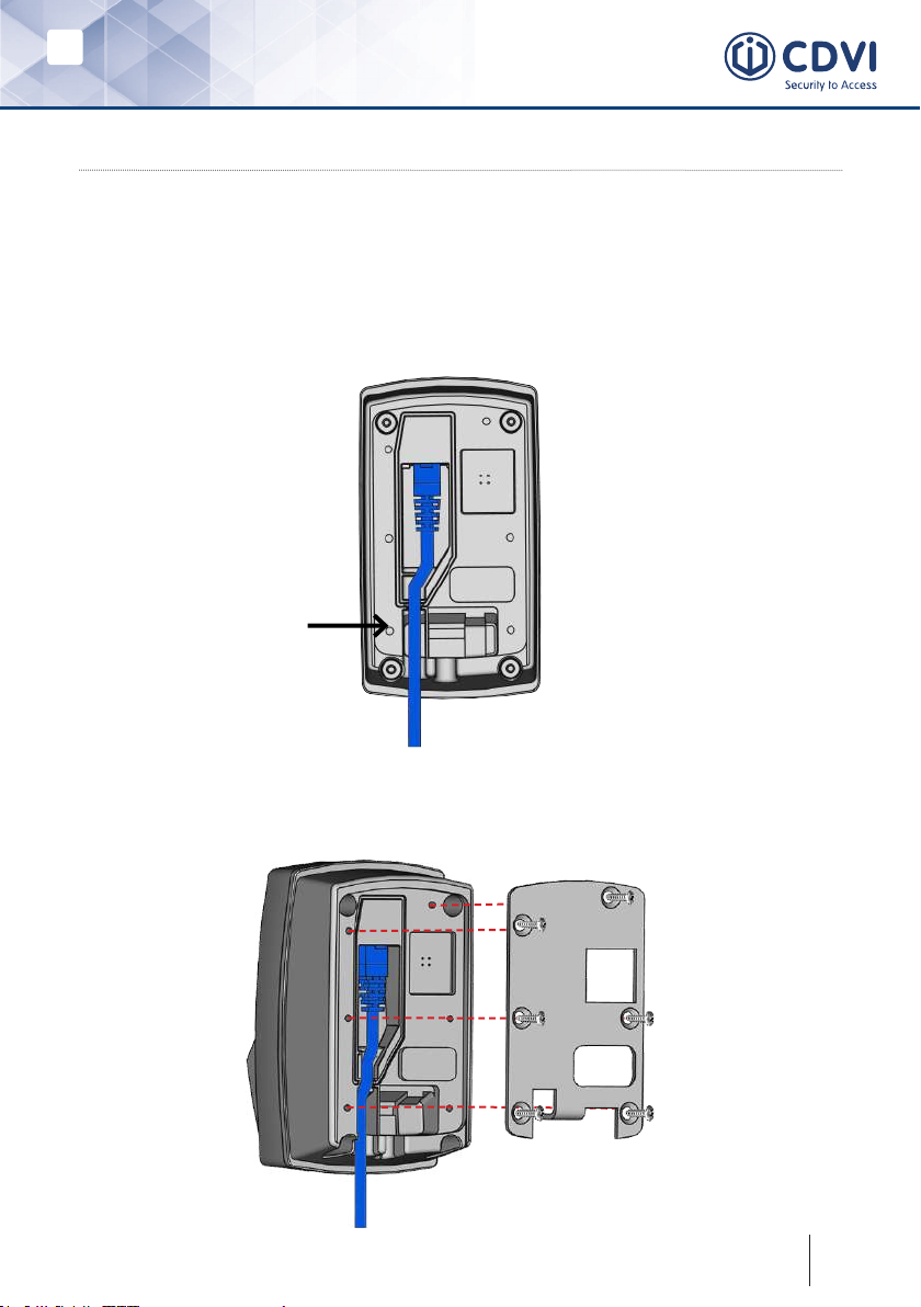
The ultimate reader can be either ush or surface mounted. Ensure you use the
correct xings and plugs for the type of wall for which you are xing the reader.
Incorrect usage can result in the Ultimate reader being unsecure.
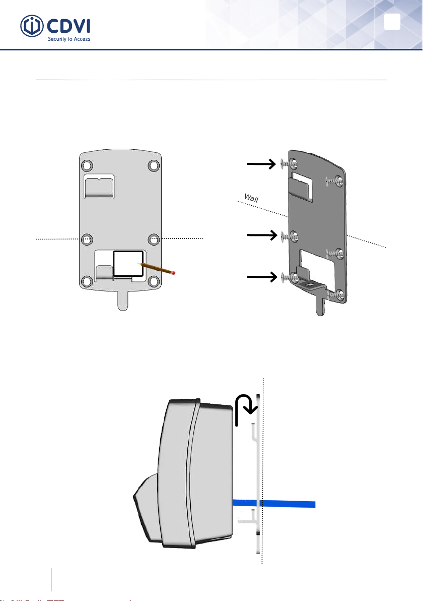
The ultimate reader should only be mounted vertically. It is not recommended to
mount any ievo reader horizontally as this can affect performance and usability.
We recommend that you install the Ultimate reader following DDA Guidelines,
installing the reader at a height of between 1m and 1.2m. This is the optimum
height for nger placement.
The ievo Control Board must be installed on the protected side of the door or
turnstile. The control board is not IP rated, but can be installed inside most IP
rated enclosures.
POWER
A single ievo Control Board with two Ultimate readers connected will pull 1.6Amps
when operating at full capacity. We recommend that you use a Surge Protected,
12 – 24V, AC (Alternating Current) or DC (Direct Current), 2Amp power supply
unit (PSU) to power each ievo Control Board.
We also recommend tting a backup battery.
It’s important you correctly calculate the amperage rating if using a shared PSU.
If using separate PSU’s for separate equipment, ensure they share a common
ground connection.
ievo equipment must be used with an EN 60950-1 or an equivalent IEC standard
complaint PSU. This is to establish adequate safety testing of the PSU to ensure
that there is enough isolation provided from the mains supply.
Please ensure that the cable used between the Power Input on the ievo Control
Board and your chosen Power Supply Unit is adequate for the current, amperage
and environment.
If you are using an ievo Control Board with a Power Over Ethernet (PoE) module,
you will require a POE+ (802.3at) rated injector or switch to supply power and
network connectivity.

6 7
EN EN
IEVO-U
ultimate™ Fingerprint Reader
Please follow ESD Safety Procedures to prevent any damage to electronic components.
READER HEAD CABLING
Each ultimate reader uses a bespoke PoE (Power over Ethernet) connection
to the ievo Control Board, carrying both power and data. Therefore, you must
use a high-quality shielded Ethernet cable to prevent power and data loss.
Each reader comes provided with a 5m CAT6 SFTP (braid-shielded cable,
foil-shielded pairs) Ethernet cable. If you need to place the reader further
than 5m away from the control board, please use a cable with the following
specication:
• Up to 50m – Cat5e/Cat6a SFTP Stranded-conductor, 26 AWG, with
shielded RJ45 connectors
• Up to 90m – Cat5e/Cat6a SFTP Solid-conductor, 24 AWG with shielded
RJ45 connectors
Note: Cat7 specication cable is too thick to use for connection to the head.
WIEGAND CABLING
We recommend that you use Belden 9534 (4 Core, shielded) cable for the
Wiegand connection between the ievo Control Board and Access Control Unit.
We recommend twisting 2 pairs for Clock and Data and using the shielding
for Ground. The distance between the ievo Control Board and Access Control
Unit must not exceed 25m.
NETWORK
Each ievo Control Board requires an Ethernet cable connected back to the
local network. We recommend using CAT5e shielded cable and the distance
must not exceed 90m.
If you are using the ievo Control Board with a Power Over Ethernet (PoE)
module, then the cable between the PoE switch or injector and ievo Control
Board must meet the below specication:
• Up to 50m – Cat5e/Cat6a SFTP Stranded-conductor, 26 AWG, with
shielded RJ45 connectors
• Up to 90m – Cat5e/Cat6a SFTP Solid-conductor, 24 AWG with shielded
RJ45 connectors

6 7
EN EN IEVO-U
ultimate™ Fingerprint Reader
6] CONTROL BOARD CONNECTIONS
Wiegand Output A
Wiegand Output B
Network OUT
Provides a network
bridge to a single ACU
Network IN
Provides Network
connection to PC or local
Network
Power input
PoE/Network IN input
when using POE module

8 9
EN EN
IEVO-U
ultimate™ Fingerprint Reader
7] DOOR WIRING EXAMPLE
ACU Power
Supply Unit
Access
Control Unit
Network
Switch
Lock
Power
Ethernet
Reader Cable
Wiegand Cable
Ground Connection

8 9
EN EN IEVO-U
ultimate™ Fingerprint Reader
8] BACK PLATE INSTALLATION
STEP 1:
Plug the ethernet cable into the back of the ultimate reader. Ensure the cable is
positioned into the duct as shown below.
The backplate is necessary to create a water tight seal and to enable the reader to
be ush or surface mounted.
STEP 2:
Attach the back plate to the back of the Ultimate reader using the 6 screws
provided.

10 11
EN EN
IEVO-U
ultimate™ Fingerprint Reader
9] SURFACE MOUNT INSTALLATION
STEP 1:
Use the wall plate to mark out the size
of the hole required for the reader
cable.
STEP 2:
Attach the wall plate to the wall using
6 counter-sunk screws, ensuring the
screw faces are ush to the wall plate.
STEP 3:
Attach the ultimate reader to the wall plate by slotting on to the plate and sliding
down until locked into position. Ensure the ethernet cable is shed through the
wall plate hole.
Wall
Wall
Wall

10 11
EN EN IEVO-U
ultimate™ Fingerprint Reader
STEP 4:
Use the security screw and tool provided to secure both plates together.
Wall
STEP 5:
Bend the security latch on the wall plate
inwards using pliers as shown below.
STEP 6:
Stretch the aesthetic seal provided
over the Ultimate reader. Push to the
back of the reader so that the seal
covers the edges of the wall plate.
Wall
Wall

12 13
EN EN
IEVO-U
ultimate™ Fingerprint Reader
10] FLUSH MOUNT INSTALLATION
Ensure you have followed the instructions for attaching the Ultimate reader to the
back plate before continuing (see: 8] Back Plate Installation).
STEP 1:
Attach the wall plate to the ush mounting place using the 4 screws provided,
ensuring the Ethernet cable is fed through the holes as shown below.
STEP 2:
Attach the Ultimate reader to the
combined wall and ush plate by
slotting on to the plate and sliding
down until locked into position.
STEP 3:
Use the security screw and tool
provided to secure the wall plate and
back plate together.

12 13
EN EN IEVO-U
ultimate™ Fingerprint Reader
Please move onto the applicable software manual for your system. You
can download all our manuals and installation guides from:
www.cdvi.co.uk/cat/ievo-biometric-solutions
STEP 4:
Bend the security latch on the wall plate
inwards using pliers as shown below.
STEP 5:
Mount the ultimate reader and ush-
kit into the wall, using the 4 security
screws and security tool provided.
Wall
STEP 6:
Afx the facia cover over the reader and click into place. Ensure the facia is the
correct way up as denoted by the arrows on the internal side.
!
INSTALLATION COMPLETE

14 15
EN EN
IEVO-U
ultimate™ Fingerprint Reader
11] PRODUCT DISPOSAL
When the product reaches the end of its useful life, it
must not be disposed of in normal waste. The product
must be disposed of at an authorised recycling plant.
The ievo Control Board contains a Lithium metal
primary coin cell battery (location highlighted below)
and should be removed by a competent engineer prior
to disposal.
The ievo equipment and the removed battery must be disposed of separately at
an authorised recycling point. Your local authority will have a centre which accepts
such waste for recycling.
WARNING: Batteries and products containing batteries must never be disposed
of in res.

14 15
EN EN IEVO-U
ultimate™ Fingerprint Reader
Notes
...............................................................................................................................
...............................................................................................................................
...............................................................................................................................
...............................................................................................................................
...............................................................................................................................
...............................................................................................................................
...............................................................................................................................
...............................................................................................................................
...............................................................................................................................
...............................................................................................................................
...............................................................................................................................
...............................................................................................................................
...............................................................................................................................
...............................................................................................................................
...............................................................................................................................
..............................................................................................................................
...............................................................................................................................
...............................................................................................................................
...............................................................................................................................
...............................................................................................................................
...............................................................................................................................
...............................................................................................................................
...............................................................................................................................
...............................................................................................................................

www.cdvigroup.com
CDVI Group
FRANCE (Headquarters)
Phone: +33 (0) 1 48 91 01 02
Extranet : CDVI_IEVO-U_IM_01_EN_A5_C
CDVI FRANCE + EXPORT
+33 (0) 1 48 91 01 02
www.cdvi.com
CDVI AMERICAS [CANADA - USA]
+1 (450) 682 7945
www.cdvi.ca
CDVI BENELUX [BELGIUM - NETHERLANDS - LUXEMBOURG]
+32 (0) 56 73 93 00
www.cdvibenelux.com
CDVI GERMANY
+49 (0) 175 2932 901
www.cdvi.de
CDVI TAIWAN
+886 (0) 42471 2188
www.cdvichina.cn
CDVI SUISSE
+41 (0) 21 882 18 41
www.cdvi.ch
CDVI CHINA
+86 (0) 10 84606132/82
www.cdvichina.cn
CDVI IBÉRICA [SPAIN - PORTUGAL]
+34 (0) 935 390 966
www.cdviberica.com
CDVI ITALIA
+39 (0) 321 90 573 - www.cdvi.it
CDVI MAROC
+212 (0) 5 22 48 09 40
www.cdvi.ma
CDVI NORDICS
[SWEDEN - DENMARK - NORWAY - FINLAND]
+46 (0) 31 760 19 30
www.cdvi.se
CDVI UK [UNITED KINGDOM - IRELAND]
+44 (0) 1628 531300
www.cdvi.co.uk
CDVI POLSKA
+48 (0) 12 659 23 44
www.cdvi.com.pl
All the information contained within this document (pictures, drawings, features, specications and dimensions)
could be perceptibly different and can be changed without prior notice.
Table of contents
Other CDVI Scanner manuals