Cooper Crouse-Hinds GmbH 99
99
9
6.26.2
6.26.2
6.2 Opening the device /Opening the device /
Opening the device /Opening the device /
Opening the device /
Electrical connectionElectrical connection
Electrical connectionElectrical connection
Electrical connection
The connection of explosion-protected
flameproof enclosures and distributions
may only be carried out by specialists.
Before opening the emergency pack,
ensure that it is not live or take the
appropriate protective measures.
Switch the „ON/OFF“ switch (light switch)
for the connected emergency lighting
luminaire to the „OFF“ position.
ii
ii
i The ON/OFF switch is not used for
switching the connected mains supply.
Even after disconnection, due to theEven after disconnection, due to the
Even after disconnection, due to theEven after disconnection, due to the
Even after disconnection, due to the
batterybattery
batterybattery
battery, the built-in components of the, the built-in components of the
, the built-in components of the, the built-in components of the
, the built-in components of the
emergency pack can still be live.emergency pack can still be live.
emergency pack can still be live.emergency pack can still be live.
emergency pack can still be live.
To maintain the explosion protection,
conductors shall be connected with special
care.
5 Use / Properties
In the event of a power failure, the explosion-
protected emergency pack can be used to
supply a connected, explosion-protected
apparatus with a power rating of max. 80 VA
(e.g. an explosion-protected floodlight) with
electric energy via the battery for 1.5 hours. If
the mains voltage is applied, the connected
apparatus is switched off.
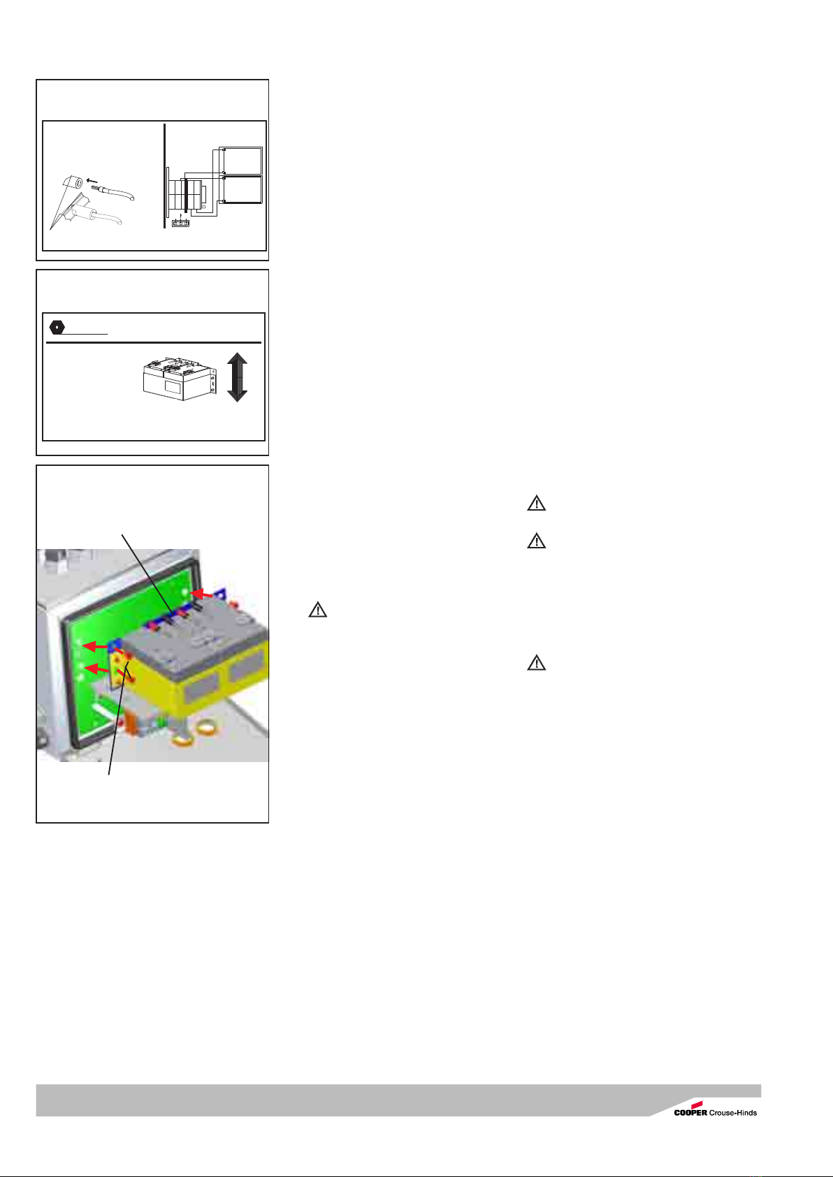
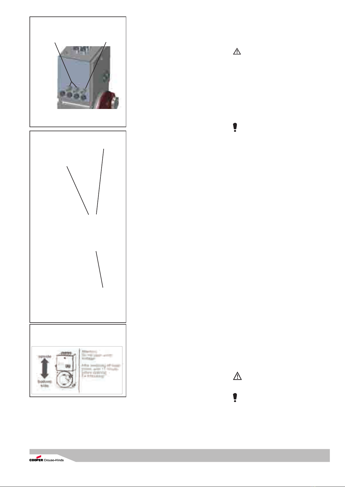
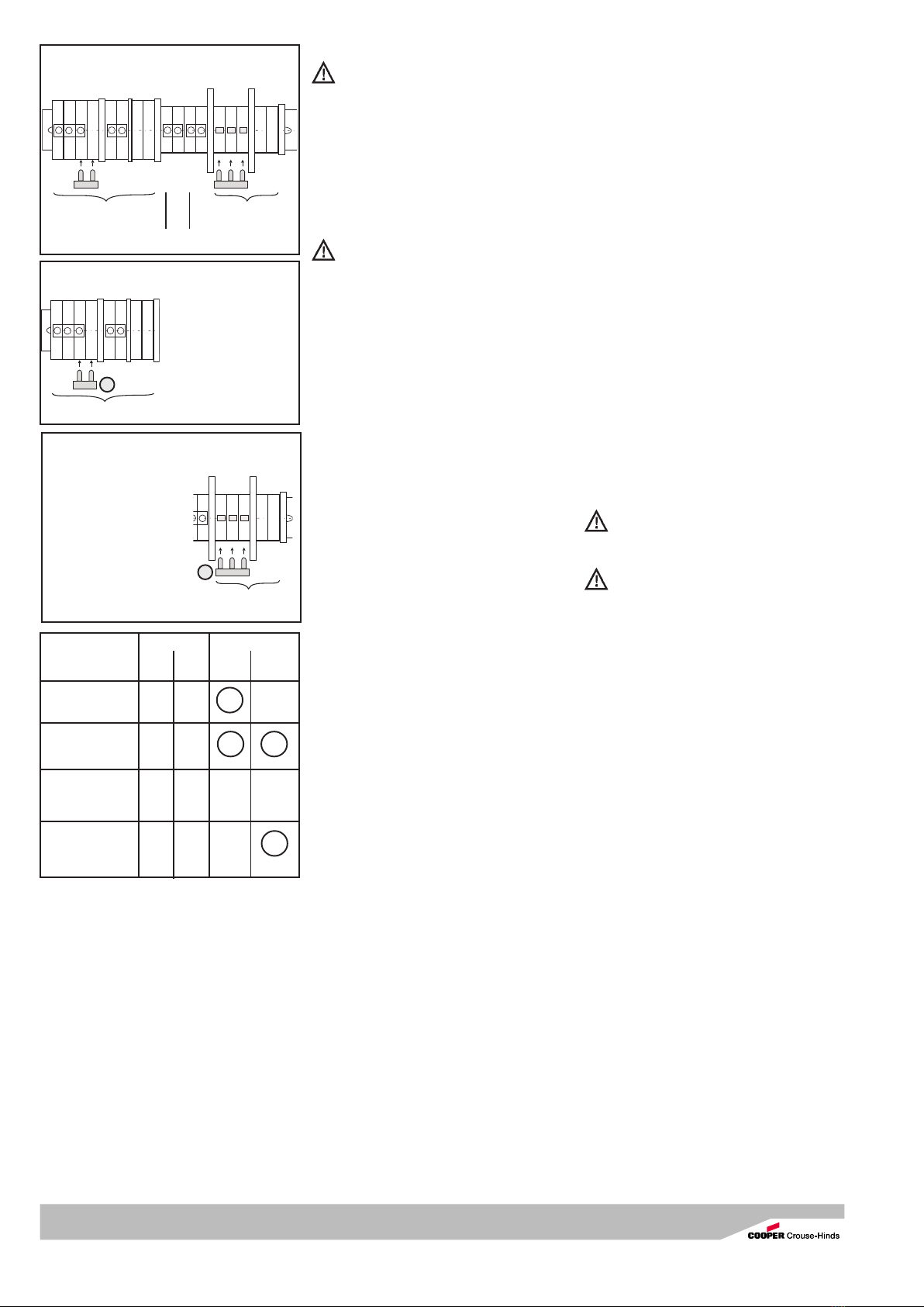
Mains voltage applies
To operate the connected floodlight with
mains voltage, the plug in jumper on the
terminal row X1 between L and L1 have to be
set. Use the round ON/OFF switch (light
switch), built in emergency pack, to switch
on/off the floodlight.
Charging battery
After connection (see Section 6) the
explosion-protected emergency pack is
charged via the built-in electronics. The
charging process is monitored by the
electronics.
For electro-chemical reasons, in the case of
temperatures below -5°C and above +40°C,
charging of the battery to the full rated
capacity cannot be guaranteed.
Emergency lighting operation
In the event of the failure of the mains voltage
supply, the built-in electronics switch over to
emergency lighting operation.
The connected apparatus is then supplied
from the battery via a built-in voltage
converter for a nominal period of 1.5 hours.
The apparatus can be switched off during
emergency lighting operation by means of the
built-in switch on the front of the enclosure
[Fig. 2].
The built-in deep-discharge protection
prevents the deep-discharging of the battery.
If the battery is run down, the connected
apparatus is switched off.
Applications other than those described
are not permissible without a written
declaration of consent from Messrs.
Cooper Crouse-Hinds / CEAG.
During operation the instructions stated
in section 7 of the operating instructions
shall be observed.
The sole responsibility with respect to the
suitability and proper use of these boxes
lies with the operator.
6 Installation
The relevant national regulations(e.g.
BetriSichV, the equipment safety law for
Germany) and the generally recognized rules
of engineering apply for the installation and
operation.
The improper installation and operation
of enclosures can result in the
invalidation of the guarantee.
6.16.1
6.16.1
6.1 MountingMounting
MountingMounting
Mounting
The explosion-protected emergency pack
can be mounted without opening the
enclosure.
When the flameproof enclosures and
distributions are mounted directly onto
the wall or onto wall or floor frames, they
shall rest evenly only on the fastening
points provided for this purpose.
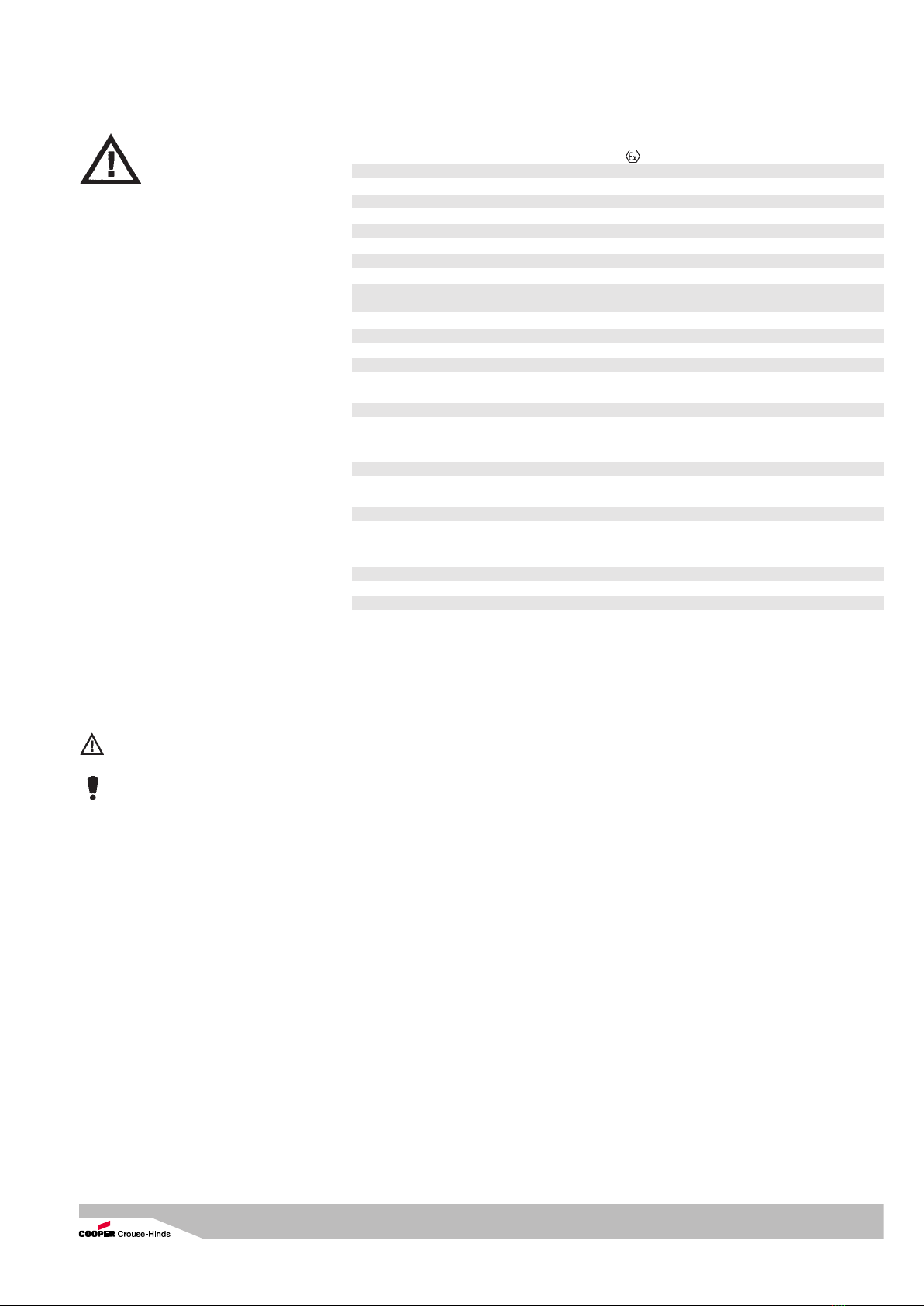
It shall be mounted in the upright
position with the connection box facing
upwards (see Fig. 2a and adhesive label(see Fig. 2a and adhesive label
(see Fig. 2a and adhesive label(see Fig. 2a and adhesive label
(see Fig. 2a and adhesive label
on the emergency pack).on the emergency pack).
on the emergency pack).on the emergency pack).
on the emergency pack).
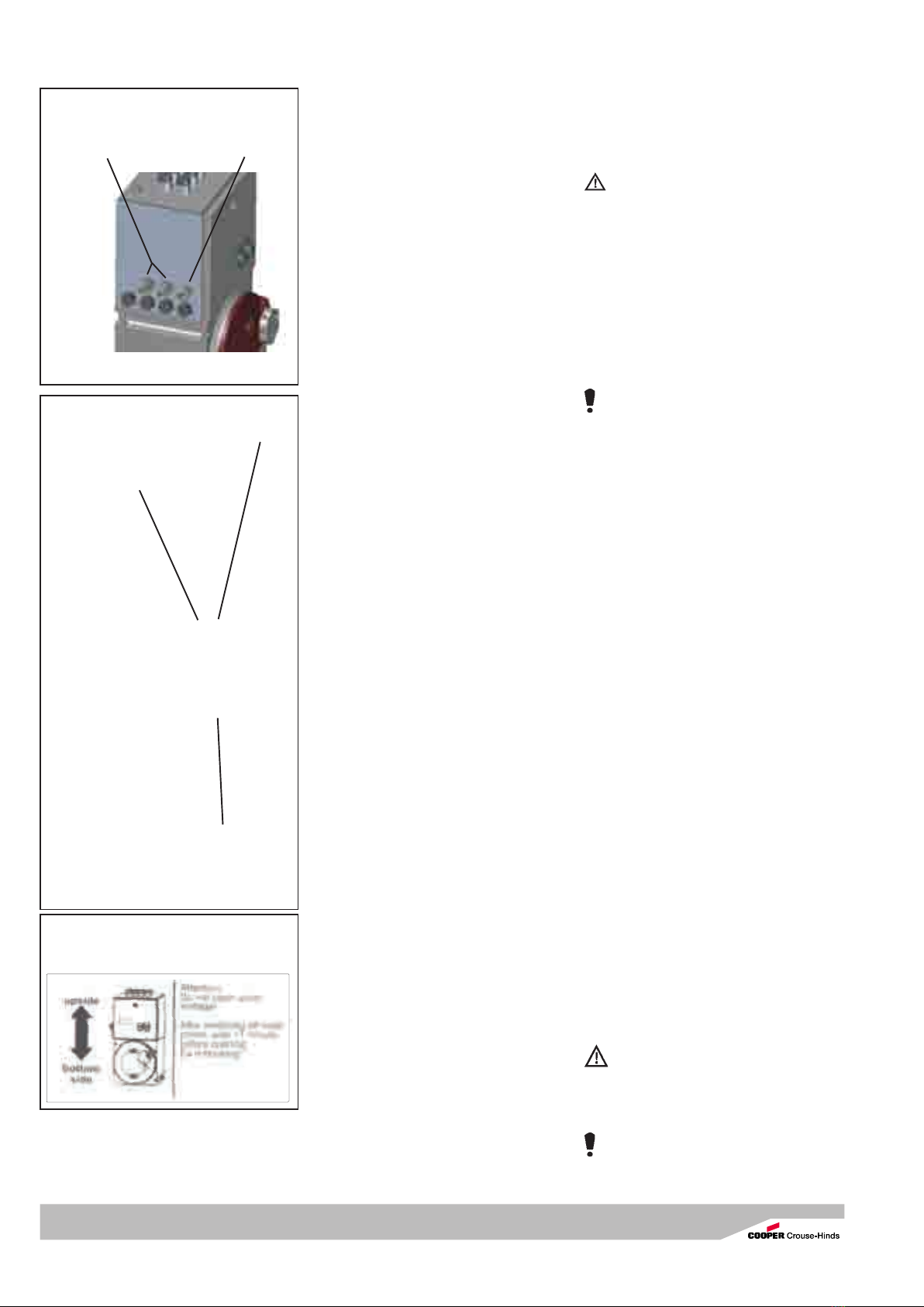
We recommend to use for mounting theWe recommend to use for mounting the
We recommend to use for mounting theWe recommend to use for mounting the
We recommend to use for mounting the
mounting brackets and spacers thosemounting brackets and spacers those
mounting brackets and spacers thosemounting brackets and spacers those
mounting brackets and spacers those
attached (see Dimension drawing).attached (see Dimension drawing).
attached (see Dimension drawing).attached (see Dimension drawing).
attached (see Dimension drawing).
The built-in breathers on the sides and the
top must not be covered over.
The screws and washers used shall match
the fixing holes. Use all the fixing lugs when
mounting the explosion-protected emergency
pack.
The fixing dimensions can be found in the
dimensional drawing on Page 1.
In the event of distributions with several
enclosures in the same size, the covers of
the flameproof enclosures shall not be
interchanged.
Which flameproof enclosure cover belongs to
which enclosure base can be determined by
identical production numbers on the inside of
the enclosure cover and the front of the
enclosure base.
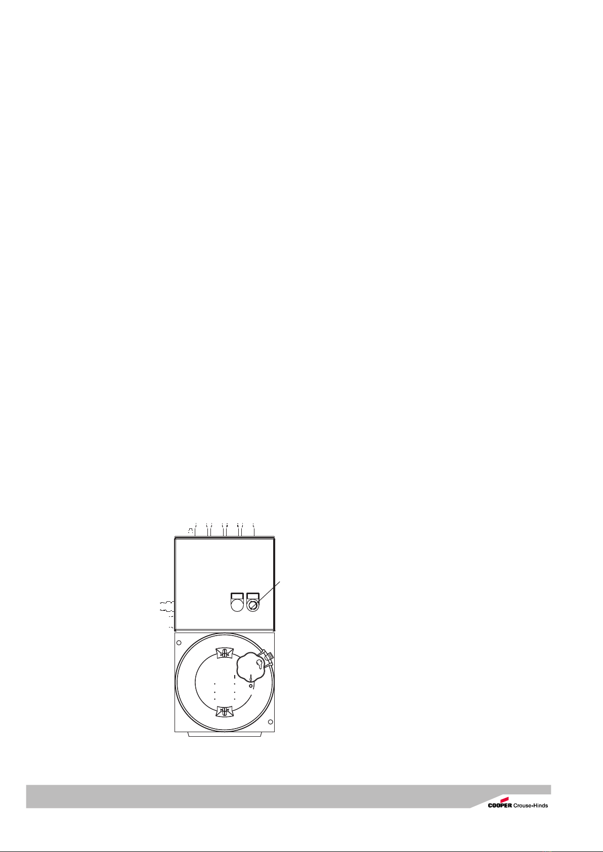
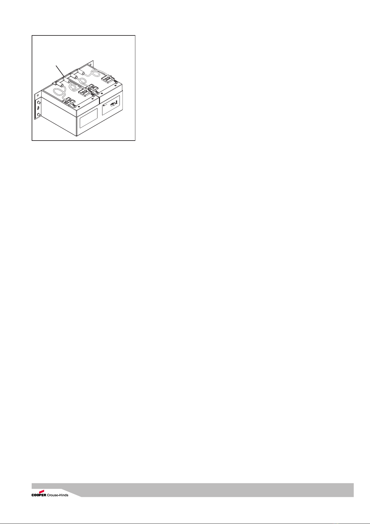
Entry
for
floodlight
Mains/supply
voltage available
Fig. 1
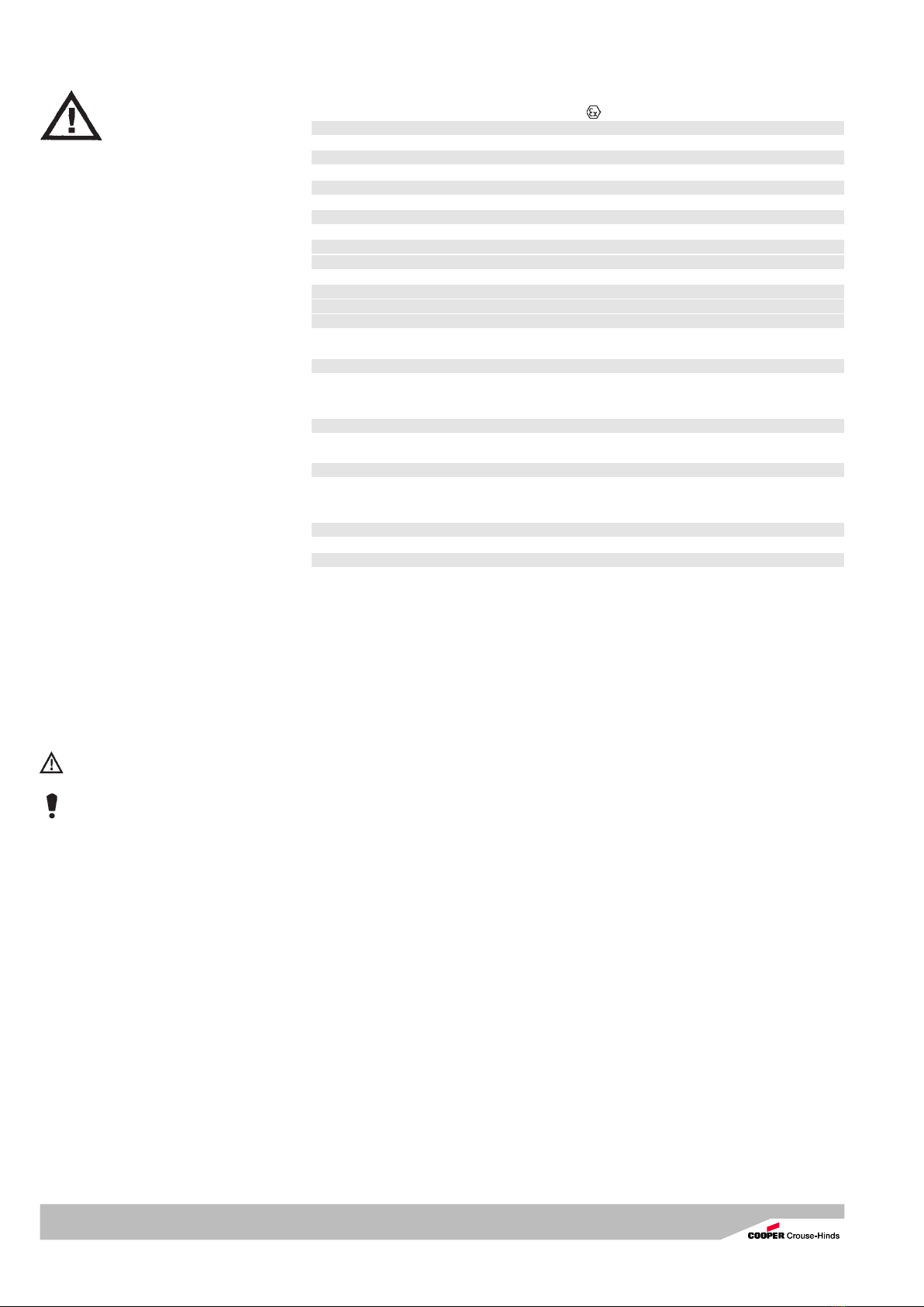
Fig. 2
Out ON
ON/OFF switch
(light switch)
for the
connected
lighting luminaire
Entry
for
mains supply
Fig. 2 a
Adhesive labels – mounting position
Vertical mounting only