Hioki U8550 User manual

LR8450(-01)メモリハイロガー用
直結ユニット
Plug-In Modules Dedicated to
LR8450 (-01) Memory HiLogger
取扱説明書 /Instruction Manual
Feb. 2020 Revised edition 1
U8550A960-01 20-02H
JA/EN
製品名
LR8450(-01)用の直結ユニットには次の 5種類があります。
U8550 電圧・温度ユニット
VOLTAGE/TEMP UNIT
U8551 ユニバーサルユニット
UNIVERSAL UNIT
U8552 電圧・温度ユニット
VOLTAGE/TEMP UNIT
U8553 高速電圧ユニット
HIGH SPEED VOLTAGE UNIT
U8554 ひずみユニット
STRAIN UNIT
はじめに
このたびは、HIOKI LR8450(-01)用直結ユニット U8550,
U8551, U8552, U8553, U8554 をご選定いただき、誠に
ありがとうございます。直結ユニットは、LR8450 または
LR8450-01 に接続できます。使用上の注意や安全について
などの詳細は、LR8450 のクイックスタートマニュアルをご
覧ください。
安全に関する表記
本書では、リスクの重大性および危険性のレベルを以下のよ
うに区分して表記します。
警告回避しなければ、作業者が死亡または重傷を負う
おそれがあることを示します。
重要操作および保守作業上、特に知っておかなければ
ならない情報や内容がある場合に記述します。
梱包内容
U8550 電圧・温度ユニット
U8551 ユニバーサルユニット
U8552 電圧・温度ユニット
U8553 高速電圧ユニット
U8554 ひずみユニット ……………………… いずれか 1
ねじ M3 ×35 mm(予備)………………………………… 2
結線確認ラベル(U8554 のみ)…………………………… 1
取扱説明書(本書)………………………………………… 1
本体に接続する
直結ユニットを本体(LR8450 またはLR8450-01)に接続し
ます。
1台の LR8450(-01)に 4ユニットまで接続できます。
警告
直結ユニットを取り付けたり取り外したりする前に、
LR8450(-01)の電源を切り、ケーブル類を外す
直結ユニットを増設しないときは、LR8450(-01)の
ユニット側のコネクターにコネクターカバーをねじ
で固定する
作業者が感電したり、直結ユニットおよびLR8450
(-01)が破損したりするおそれがあります。
用意するもの:プラスドライバー(No.2)
1
LR8450(-01)の電源を切り、ACアダプタを外す
2
LR8450(-01)のコネクターカバーの、ねじ2本を外す
3
コネクターカバーを取り外す
LR8450(-01)から外したコネクターカバーは、無く
さないように保管してください。
2
3
4
直結ユニットを LR8450(-01)のコネクターに接続する
5
手順
2
で外した、ねじ 2本を挿入し、締め付ける
4
5
複数台の直結ユニットをLR8450(-01)に取り付ける場合
は、次のように取り付けてください。
また、増設しない直結ユニットのコネクターカバーは取り外
さないでください。
OK
NO
OK
NO
直結ユニットを 1台接続する場合 直結ユニットを3台接続する場合
かに接続します。 , , または , , に接続します。
次のような接続をすると、画面にエラーが表示されます。
OK
NO
直結ユニットを片側だけ 2台以上
接続した場合
直結ユニットを 5台以上
接続した場合
OK
NO
重要
直結ユニットには予備のねじ(M3 ×35 mm)が 2本付属し
ています。
無くさないようにご注意ください。
Feb. 2020 Revised edition 1
U8550A960-01 20-02H
Plug-In Modules Dedicated to
LR8450 (-01) Memory HiLogger
Instruction Manual
EN
Model names
Five dierent types of built-in modules are available for the
LR8450 (-01).
U8550 Voltage/Temp Unit
U8551 Universal Unit
U8552 Voltage/Temp Unit
U8553 High Speed Voltage Unit
U8554 Strain Unit
Introduction
Thank you for choosing the U8550/U8551/U8552/U8553/
U8554, built-in modules dedicated to Hioki LR8450/LR8450-
01 Memory HiLogger, The built-in modules can be connected
to the LR8450/LR8450-01. For information, such as operating
precautions and safety, see LR8450 Quick Start Manual.
Safety notations
This manual classies seriousness of risks and hazard levels
as described below.
WARNING
Indicates a potentially hazardous situation
that, if not avoided, could result in death of
or serious injury to the operator.
IMPORTANT
Indicates information or content that is
particularly important from the standpoint of
operating or maintaining the device.
Package Contents
U8550 Voltage/Temp Unit
U8551 Universal Unit
U8552 Voltage/Temp Unit
U8553 High Speed Voltage Unit
U8554 Strain Unit ……………………… any one of them
Screw M3×35 mm (spare)………………………………… 2
Connection conrmation label (U8554 only) …………… 1
Instruction Manual (this manual) ………………………… 1
Connecting the Module to the
Instrument
Connect the built-in module to the instrument (LR8450/
LR8450-01).
You can connect up to four modules to one LR8450 (-01).
WARNING
Turn o the instrument and disconnect any
cables before connecting or removing any plug-
in modules.
When not using a plug-in module slot, secure the
connector cover over the instrument’s module
connector with the screws.
Failure to do so could cause electric shock or damage
the plug-in module and the LR8450 (-01).
You will need: A Phillip’s head screwdriver (No. 2)
1
Turn o the LR8450 (-01) and disconnect the AC
Adapter.
2
Remove the two screws from the connector cover
of the LR8450 (-01).
3
Remove the connector cover.
Store the connector cover removed from the LR8450
(-01) for future use.
2
3
4
Connect the plug-in module to the connector on the
LR8450 (-01).
5
Insert and tighten the two screws removed in step 2.
4
5
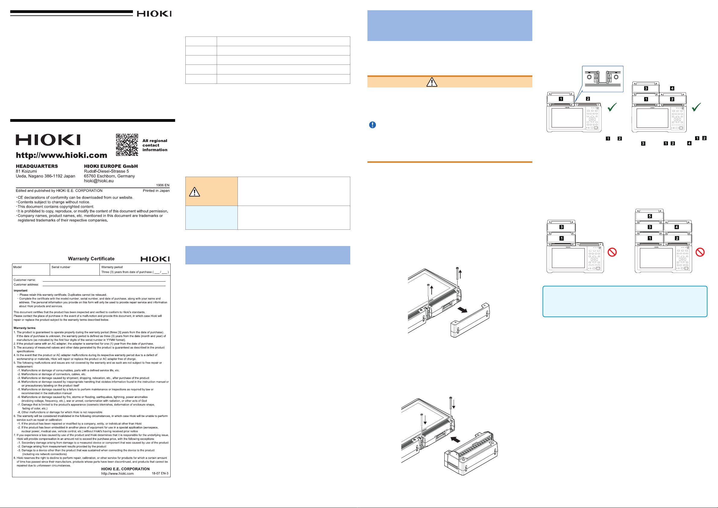
If installing multiple plug-in modules on the LR8450 (-01), do
so in the order indicated in the diagram below.
Do not remove the connector covers for any plug-in module
slots not in use.
OK
NO
OK
NO
When connecting 1 plug-in module When connecting 3 plug-in
modules
Connect the module to slot or . Connect the modules to slots , ,
and or slots , , and .
Connecting plug-in units as shown below will cause an error
to be displayed on the screen.
OK
NO
When connecting 2 or more
plug-in modules on one side
When connecting 5 or more
plug-in modules
OK
NO
IMPORTANT
Plug-in modules ship with two spare screws
(M3 × 35 mm).
Exercise care not to lose them.
This manual suits for next models
4
Other Hioki Control Unit manuals


Popular Control Unit manuals by other brands

Festo
Festo Compact Performance CP-FB6-E Brief description

Elo TouchSystems
Elo TouchSystems DMS-SA19P-EXTME Quick installation guide

JS Automation
JS Automation MPC3034A user manual

JAUDT
JAUDT SW GII 6406 Series Translation of the original operating instructions

Spektrum
Spektrum Air Module System manual

BOC Edwards
BOC Edwards Q Series instruction manual

KHADAS
KHADAS BT Magic quick start

Etherma
Etherma eNEXHO-IL Assembly and operating instructions

PMFoundations
PMFoundations Attenuverter Assembly guide

GEA
GEA VARIVENT Operating instruction

Walther Systemtechnik
Walther Systemtechnik VMS-05 Assembly instructions

Altronix
Altronix LINQ8PD Installation and programming manual


