During maintenance & inspection
◆Maintenance & inspection must be carried out by personnel who have the necessary electrical
training and experience.
◆Do not touch the terminals while the power is on. Failure to comply may result in electric shock or
malfunction.
◆Disconnect all external power supplies of the system before cleaning the module or re-tightening
screws on the terminal block or screws of the connector. Failure to comply may result in electric
shock.
◆Disconnect all external power supplies of the system before removing the module or connecting/
removing the communication wirings. Failure to comply may result in electric shock or malfunction.
◆Get acquainted with the guide and ensure safety before online modication, forcible output, and RUN/
STOP operation.
◆Disconnect the power supply before installing/removing the extension card.
At disposal
◆Treat scrapped module as industrial waste. Dispose the battery according to local laws and
regulations.
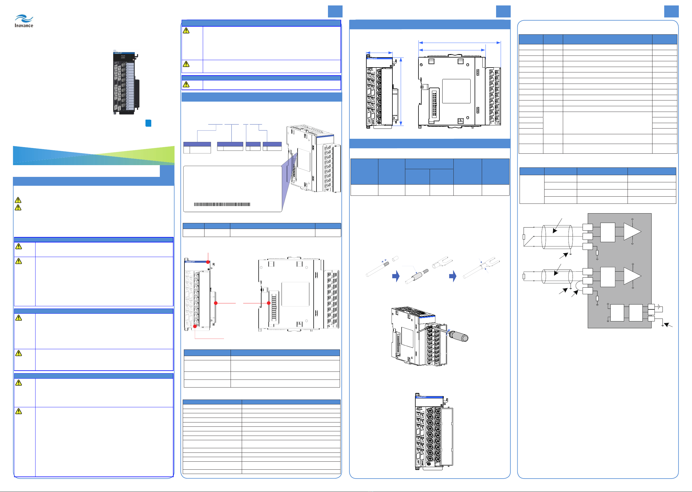
■Mounting Dimensions
Figure 3 Mounting dimensions (in mm)
■Cable Selection
Cable Name Model
Applicable Cable
Diameter
Manufacturer Crimping Tool
Chinese
standard/
MM2
American
standard/
AWG
Y-shaped
cable lug TNS 1.25-3 0.5–0.75 22–18 Suzhou
Yuanli
RYO-8
YYT-8
Those cable lugs are applicable to digital and analog temperature modules, and the cable
rated temperature needs to be higher than 75 °C.
■Cable Preparing Procedures
1) Strip the insulation layer of the cable by 6 mm.
2) Pass the cable through the tube of proper wire size.
3) Insert the exposed end into the hole of the cable lug, and then crimp it with the
recommended crimping tool.
4) Use a 20 mm heat-shrinkable tube (Φ3) to wrap the copper tube of the cable
lug and then perform thermal shrinkage.
6
Pass through the tube of
proper wire size
Crimp it with a
crimping tool
Figure 4 Diagram of cable preparation
5) Put the cable lug onto the terminal and tighten the screw with a screwdriver.
The tightening torque cannot be greater than 0.8 N.m.
Figure 5 Connecting cable to terminal block
■Terminal Arrangement
The gure below shows the ports of the AM600-4PT module.
Figure 5 Terminal denition of the AM600-4PT module
■Model and Nameplate
Product Information
AM
Inovance medium-sized PLC
Automation-Motion
Series
600
600 series controller
Number of Channels
4
4 channels
Input Type
Thermal resistor input
PT
Nameplate
MODEL˖AM600-4PT
POWER INPUT˖24VDC 100mA
OUTPUT˖NONE
VER ˖xxxxx
01022087YE400001
01022087YE400001
Figure 1 Description of model and nameplate
Model Classication Description Applicable to
AM600-4PT Temperature
module
4-Channel thermal resistor temperature collection module,
supporting multiple types of thermal resistors
AM600 series,
H3U
■External Interfaces
RUN
ERR
User input terminal
Local extension
back-end
interface
Local
extension
front-end
interface
Figure 2 Diagram of the AM600-4PT temperature module interfaces
Interface Name Function
User input terminals 4 channels of thermal resistor inputs
Signal indicators
RUN: operation state indicator, which is turned on during normal operation and
turned off when a fault occurs
ERR: error state indicator, which is turned on when a fault occurs
Local expansion module back-end
interface Connect back-end module, not supporting hot plugging
Local expansion module front-end
interface Connect front-end module, not supporting hot plugging
■General Specications
Item Specications
Input channel 4
Supply voltage 24 VDC (20.4 VDC to 28.8 VDC) (–15% to +20%)
Internal 5 V power consumption 85 mA (typical value)
Sensor type Thermal resistor: Pt100, Pt500, Pt1000 , and Cu100
Display mode: Celsius degree (°C), and Fahrenheit degree (°F)
Thermal resistor wiring method Two wires/Three wires
Resolution 24 bits
Sensitivity 0.1 °C or 0.1 °F
Sampling cycle 250 ms, 500 ms, or 1000 ms (The sampling cycles of the four channels can
be set separately using software.)
Filter time 0s to 100s (The lter time can be set using software. The default value is 5s.)
Accuracy (normal temperature: 25 °C) Full scale x (±0.3%)
Accuracy (ambient temperature: 0 to 55 °F) Full scale x (±1%)
Isolation method I/O terminals isolated from power supply;
Isolation between channels
System program updated via USB interface
Safety Information and Precautions
User Guide
AM600-4PT Temperature Module
Safety information and precautions are identied into two grades: Warning and Caution. Please make
sure to operate properly with adequate safety assurance.
: Indicates the improper operation which, if not avoided, may cause death or serious injury;
: Indicates the improper operation which, if not avoided, may cause moderate or minor
injury, as well as equipment damage.
In some cases, even failure to follow "Cautions" may also lead to serious consequences. Please make
sure to follow both warnings and cautions; otherwise, it may cause death or serious injury, as well as
product and relevant equipment and system damage.
Please keep this guide well so that it can be read when necessary and forward this guide to the end user.
During control system design
◆Provide a safety circuit outside the PLC so that the control system can still work safely once external
power failure or PLC fault occurs.
◆Add a fuse or circuit breaker because the module may smoke or catch re due to long-time
overcurrent caused by operation above rated current or load short-circuit.
◆An emergency stop circuit, a protection circuit, a forward/reverse operation interlocked circuit, and a
upper position limit and lower position limit interlocked circuit must be set in the external circuits of the
PLC to prevent damage to the machine.
◆To ensure safe operation, for output signals related to critical accidents, please design external
protection circuit and safety mechanism;
◆Once the PLC CPU detects abnormality in the system, all outputs may be closed; however, when a
fault occurs in the controller circuit, the output may not be under control. Therefore, it is necessary to
design an appropriate external control circuit to ensure normal operation;
◆If the PLC's output units such as relays or transistors are damaged, the output may fail to switch
between ON and OFF states according to the commands;
◆The PLC is designed to be used in indoor electrical environment (overvoltage category II). The
power supply must have a system-level lightning protection device, assuring that overvoltage due to
lightning shock can't be applied to the PLC's power supply input terminals, signal input terminals and
output terminals and so forth, so as to avoid damage to the equipment.
During installation
◆Installation must be carried out by the specialists who have received the necessary electrical training
and understood enough electrical knowledge.
◆Disconnect all external power supplies of the system before module assembly/disassembly and wiring.
Failure to do so may result in electric shock, module fault or malfunction.
◆Do not use the PLC where there are dust, oil smoke, conductive dust, corrosive or combustible gases,
or exposed to high temperature, condensation, wind & rain, or subject to vibration and impact. Electric
shock, re and malfunction may also result in damage or deterioration to the product.
◆The PLC is open-type equipment that must be installed in a control cabinet with lock (cabinet housing
protection > IP20). Only the personnel who have received the necessary electrical training and
understood enough electrical knowledge can open the cabinet.
◆Prevent metal lings and wire ends from dropping into ventilation holes of the PLC during installation.
Otherwise it may result in re, fault and malfunction.
◆Ensure there are no foreign matters on the ventilation surface. Failure to comply may result in poor
ventilation, which may cause re, fault and malfunction.
◆Ensure the module is connected to the respective connector securely and hook the module rmly.
Improper installation may result in malfunction, fault or fall-off.
During wiring
◆Wiring must be carried out by personnel who have received the necessary electrical training and
understood enough electrical knowledge.
◆Disconnect all external power supplies of the system before wiring. Failure to comply may result in
electric shock, module fault or malfunction.
◆Install the terminal cover attached to the product before power-on or operation after wiring is
completed. Failure to comply may result in electric shock.
◆Perform good insulation on terminals so that insulation distance between cables will not reduce after cables
are connected to terminals. Failure to comply may result in electric shock or damage to the equipment.
◆Prevent metal lings and wire ends from dropping into ventilation holes of the PLC at wiring. Failure
to comply may result in re, fault and malfunction.
◆The external wiring specication and installation method must comply with local regulations. For
details, see the wiring section in this guide.
◆To ensure safety of equipment and operator, use cables with sufcient diameter and connect the
cables to ground reliably.
◆Wire the module correctly after making clear of the connector type. Failure to comply may result in
module and external equipment fault.
◆Tighten bolts on the terminal block in the specied torque range. If the terminal is not tight, short-
circuit, re or malfunction may be caused. If the terminal is too tight, fall-off, short-circuit, re or
malfunction may be caused.
◆If the connector is used to connect with external equipment, perform correct crimping or welding with
the tool specied by manufacturer. If connection is in poor contact, short-circuit, re or malfunction
may be caused.
◆A label on the top of the module is to prevent foreign matters entering the module. Do not remove the
label during wiring. Remember to remove it before system operation, facilitating ventilation.
◆Do not bundle control wires, communication wires and power cables together. They must be run with
distance of more than 100 mm. Otherwise, noise may result in malfunction.
◆Select shielded cable for high-frequency signal input/output in applications with serious interference
so as to enhance immunity to interference of the system.
Product Information
Mechanical Design Reference
Electrical Design Reference
■Terminal Denition
Network
Name Type Function Terminal No.
IN0 A Input Temperature measurement resistor A of channel 0 1
IN0 B Input Temperature measurement resistor B of channel 0 3
IN0 b Input Temperature measurement resistor b of channel 0 5
IN1 A Input Temperature measurement resistor A of channel 1 2
IN1 B Input Temperature measurement resistor B of channel 1 4
IN1 b Input Temperature measurement resistor b of channel 1 6
IN2 A Input Temperature measurement resistor A of channel 2 9
IN2 B Input Temperature measurement resistor B of channel 2 11
IN2 b Input Temperature measurement resistor b of channel 2 13
IN3 A Input Temperature measurement resistor A of channel 3 10
IN3 B Input Temperature measurement resistor B of channel 3 12
IN3 b Input Temperature measurement resistor b of channel 3 14
NC
Reserved Reserved
7
NC 8
NC 15
NC 16
24 V Power
supply +24 V power supply 17
COM Power
supply 24 V power ground 18
■Detection Mode Specications
Item Sensor Temperature Range (°C) Temperature Range (°F)
Thermal
Resistor
Type
Pt100 –200.0 °C to 850.0 °C –328.0 °F to 1562.0 °F
Pt500 –200.0 °C to 850.0 °C –328.0 °F to 1562.0 °F
Pt1000 –200.0 °C to 850.0 °C –328.0 °F to 1562.0 °F
Cu00 –50.0 °C to 150.0 °C –58.0 °F to 302.0 °F
■External Wiring
PT
24
V
COM
FG
Filter
DC/DC
converter
Filter
Filter
INA
INB
INb
INA
INB
INb
AGND
AGND
AGND
AGND
AGND
5V
5V
5V
24 V
External
DC power
γ1
γ3
PT
γ1
γ2
γ3
bTwo-wire system
aThree-wire system
Figure 6 AM600-4PT module wiring diagram
*1. Shielded cables need to be used.
*2. When the two-wire system is used in wiring, the INB and INb channels need to be
shorted. In this case, resistors on the cable affect the measurement value.
*3. Cables with low wire resistance in which there is no resistance difference among the
three wires need to be used.
*4 The module should be mounted on a well-grounded metal bracket, and the metal
shrapnel at the bottom of the module must be in good contact with the bracket.
■Wiring Precautions
Do not bundle the cable together with AC cable, main lines, high voltage cable and so
forth; otherwise, it may result in an increased noise, surge and induction.
Apply single-point grounding for the shielding of shielded cable and solder sealed cable.
Tubed and solderless crimp terminal cannot be used with a terminal block. It is
recommended that a marking sleeve or insulation sleeve be used to cover the cable
connector part of the crimp terminals.
A00
Data Code: 19010673
Thank you for purchasing the AM600-4PT module
developed and manufactured independently by
Inovance.
AM600-4PT is a 4-channel thermal resistor temperature
collection module used together with the AM600 series
medium-sized PLC and the H3U series PLC main
modules. It supports temperature collection of multiple
types of thermal resistors, and provides a resolution of
up to 24 bits.
This guide describes the specications, characteristics
and using methods of the product. Please read this
guide carefully before using to ensure more safely
usage. Please refer to the AM600 Series PLC Hardware
Manual and the AM600 Series PLC Software Manual to
understand the use of the user program development
environment and design method of the user program of
the product. You can download the latest materials from
www.inovance.cn.
1
234
User Guide


