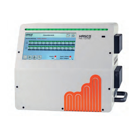
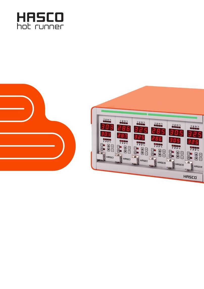
Hasco H1250 Series User manual

H1250/...
Basezone
Control unit
Operating instructions


Instruction manual H1250
HASCO hot runner 3
Foreword
Thank you for choosing a HASCO hot runner product.
These operating instructions are intended for everyone who works with HASCO hot runner technology and explain how to
safely handle HASCO hot runner products.
These operating instructions must be read carefully by personnel whenever a product is brought into operation for the first
time. They must always be readily available during operation.
The operating instructions form the basis for the safe handling of HASCO hot runner technology. The instructions and
information given here, and particularly the safety rules, must be followed under all circumstances.
The general safety regulations and accident prevention regulations at the location in question must always also be
observed by personnel.
The operating instructions contain illustrations which serve for a better understanding only. In addition, the scope of
delivery for special versions or the latest technical changes can lead to deviations from the actual version supplied.
With this edition, all previous versions lose their validity.
Read carefully prior to use
and keep for future reference.

4 HASCO hot runner
CONTENTS PAGE
1. Introduction 5
2. Special features 5
3. Technical data 5
4. Electrical connection 6
4.1 Pin diagram 6
5. Button and display functions 7
6. Displays 7
6.1 Alarm displays 8
6.2 Function displays 9
7. Function buttons 10
8. Controller start-up 10
8.1 Switching on / Soft Start 10
8.2. Manual mode 11
9. Programming 11
9.1 Factory settings 11
10. Menu items 12
11. Safety information 13

Instruction manual H1250
HASCO hot runner 5
1. Introduction
The HASCO H 1250 control unit offers precision control and practically orientated operation.
2. Special Features
- 1 to 2 control zones
- Optimum control performance
- Programmable soft start
- Power display in amps and % output
- Clear alarm diagnosis
- Manual or automatic switch to manual mode
- Boost function
- Temperature reduction
- Thermocouple monitoring
- Heating circuit monitoring
The H 1250…control unit satisfies the key protection requirements
as per the EU Directives.
3. Technical Data
H1250/1x16 H1250/2x16 H1250/4x16
Dimensions (B x H x T) 210 x 160 x 100 210 x 160 x 100 210 x 175 x 160
Mains voltage standard 230VAC ±10% / 50 –60 Hz 400V 3N ~ ±10% / 50–60 Hz 400V 3N ~±10% / 50–60 Hz
Unit protection external 16A 16A / Phase 32A / Phase
Power output Max. 3600W Max 3600W / zone Max 3600W / zone
Thermocouple Fe-CuNi Typ J Fe-CuNi Typ J Fe-CuNi Typ J
Control range 30 –500°C 30 –500°C 30 –500°C
Control accurancy >1°C under optimum conditions >1°C under optimum conditions >1°C under optimum conditions
Ambient temperature 10 –40°C 10 –40°C 10 –40°C
Power fuse FF 16A / 500V FF 16A / 500V FF 16A / 500V
Protection type IP 21 / EN 60529 IP 21 / EN 60529 IP 21 / EN 60529

6 HASCO hot runner
Switching off all the outputs or individual zones will not protect any of the outputs against hazardous
voltages!
Before working on the connected heating elements, the associated connections must be unplugged, or
the entire H 1250 control unit disconnected from the mains power!
Before the H 1250 is opened, it must be disconnected from the mains power!
4. Electrical connection
The H 1225/... power/signal cable is to be used for the power and thermocouple connections between the tool and the
control unit.
If all the control zones in the H 1250 /. . . are used, it is essential to observe the following:
Maximum power consumption
H1250/1x16 …. 3600 Watt
H1250/2x16 …. 7200 Watt
H1250/4x16 …. 14400 Watt
4.1 Pin diagram
H 1250/1/16 H 1250/2/16
H 1250/4x16

Instruction manual H1250
HASCO hot runner 7
5. Button and display functions
Error displays
Buttons
actual value
Setpoint value
Parameter
Setting
6. Displays
Actual value display
Actual temperature in °C
Parameter - menu items
Set point display
Set point temperature in °C
Power output in amps and heating output in % - see switch over buttons for automatic control and PRG.
Parameter values
Operating mode
Manual mode
Reduced temperature
Boost function

8 HASCO hot runner
6.1 Alarm displays
Thermocouple error
Lights continuously when a thermocouple is broken or reversed.
The actual value display shows "- - -".
If automatic actuator operation is activated, the current heating power of the controller
appears in the set point display after a short time.
Temperature deviation
Lights during the heating phase until the setpoint temperature is reached,
and if the temperature falls below the set limit temperatures.
Excess current
Lights up if the set maximum current is exceeded.
Heating circuit interrupted
Lights up in the event of a defective FF16A fuse on the module, or with a heating failure or
cable fracture.

Instruction manual H1250
HASCO hot runner 9
6.2 Function displays
Set point value
Temperature display °C
Second set point value temperature reduction
Display for "lowering the set point temperature", factory setting 150°C.
The temperature can be changed with the arrow buttons.
This function is activated via the PRG button.
This requires the control unit to have been deactivated via the I/O button.
Set point value display = OFF
If the control unit is switched off and on again with the main power switch,
Previous set point is reactivated.
Third set point value temperature increase
Display for "raising set point temperature", factory setting 250°C.
This can be changed with the arrow buttons.
This function is activated via the PRG button.
This requires the control unit to have been deactivated via the I/O button.
Set point value display = OFF
If the control unit is switched off and on again with the main power switch,
Previous set point is reactivated.
Heating output
The button can be used to display the current heating output in % in the set point value
display.

10 HASCO hot runner
7. Function buttons
On - off button
This activates and deactivates the control unit.
Up - down buttons
Select set point temperature.
Change parameter values.
Manual mode button
Activate manual mode.
Automatic mode / current value button
Activate automatic mode.
Current measurement.
8. Controller start-up
8.1 Switching on / soft start
After a careful check of the cables, connect the tool to the control unit.
Switch on the control unit at the main switch.
Use the arrow buttons to activate the set point display and enter the desired set point value.
The controller module is switched on with the I/O switch and the soft start is activated for 5 minutes
(factory setting) up to 120°C max. SOF appears in the set point value display.
The "Temperature deviation" alarm display will light up.
After the soft start has been completed, the pre-set set point value will be displayed.
The control unit now heats up the tool uniformly.

Instruction manual H1250
HASCO hot runner 11
The "Temperature deviation" alarm display will light up.
Once the set point temperature on the unit has been reached, production can be run with the calculated parameters.
The "Temperature deviation" alarm display will go out.
If malfunctions occur during start-up, the reason for the error will be shown by the appropriate displays on the control unit
(see Page 5).
The soft start can be bypassed by pressing the automatic control / PRG button combination.
The automatic mode button must be pressed first in this case.
After switching the unit off and on with the mains power switch, the soft start will be active again.
The soft start can be permanently deactivated via parameter 17 (page 8).
Note! The soft start provides protection for the electric components.
It is recommended to run a soft start!
8.2 Manual mode
Manual mode is called up by pressing the "Manual mode" button.
The desired heating output (%) is set with the aid of the arrow buttons.
9. Programming
The programming function is activated by pressing the PRG button (for about 3 sec.).
The first menu item "P00" appears in the actual value display.
The setpoint value display shows the value of the parameter.
This can be changed with the arrow buttons.
Pressing the PRG button twice again will call up the next parameter.
To exit program mode, the PRG button must be pressed for approx. 3 sec.
The control unit confirms that the changed parameters have been permanently saved by the decimal point in the top right-
hand display blinking for a short time.
The temperature control will continue to operate normally in parameter mode.
9.1. Reset all parameters / factory settings
To return all the parameters to the factory setting, the "PRG" button must be briefly pressed at the same time as the
operating voltage is switched on with the mains power switch. "RES" appears in the display.

12 HASCO hot runner
10. Menu items
Menu items Ex works Value range Comment
P00 Offset cold junction temperature 0 -9.9 –9.9 °C
P02 Re-determine control parameters 1 0 –1 1= activated
P03 Edit established dead time X 0 –100
P04 Manual entry of dead time 0 –100
P05 Display residual time soft start X sec.
P06 Soft start duration 300 120 –999 sec.
P07 Upper temperature alarm limit 10 0 –500 0 = deactivated
P08 Lower temperature limit 10 0 –500 0 = deactivated
P09 Temperature alarm mode 1 0 = Off / 1 = ON
P10 Min. load current 0.2 A 0 –16 A 0 = deactivated
P11 Max. heating output for soft start 35% 0 –100%
P12 Max. heating output after soft start 100% 0 –100%
P13 Max. heating output in manual mode 100% 0 –100%
P14 Conversion 50 / 60Hz 50Hz 50 –60Hz
P15 Language 0 0 –1 0 = German
1 = English
P16 Display brightness 0 0 –1
P17 Soft start ON = 1 / OFF = 0 1 0 -1
P18 No soft start as of actual temperature 100°C 50 –100°C
P19 Max. setpoint value 500°C 30 –500°C
P20 Automatic switch to manual mode 0 0 -1 0 = deactivated

Instruction manual H1250
HASCO hot runner 13
11. Safety information
Connecting cable H 1225/... and connection housing H 1227/. . . are to be used for the electrical connections (power and
thermocouple connections) between the control unit and the tool.
This guarantees optimum control accuracy.
The control units are coordinated with HASCO's range of standard elements.
No guarantee of trouble-free functioning can be given if components from other companies are used.
Connection, repair and maintenance work may only be carried out by trained electrical technicians.
During work on the control units and on the cables, devices, machines and tools connected to them, all parts must be
disconnected from the mains power.
The system must also be safeguarded against being unintentionally turned on again.
The H 1225/. . . power/signal cables must be regularly inspected for mechanical damage and replaced if necessary.
The units must be positioned so that they are free-standing, to ensure sufficient ventilation and cooling.
The control units must be protected against moisture and wet.
The units are to be used in a technically meaningful way.
Before changing the fuse, the unit must be disconnected from the mains power.
Only experienced users should operate this equipment.
02.21 / JS
© by HASCO Hasenclever GmbH + Co KG, Postfach 1720, D-58467 Lüdenscheid,
Subject to technical modifications
Please always check all the data against the product information we publish in the internet.

www.hasco.com
Built to Run.
This manual suits for next models
3
Table of contents
Other Hasco Control Unit manuals
Popular Control Unit manuals by other brands

Symmons
Symmons Evolution EVOFQ038KIT installation guide

Siemens
Siemens SIM-16RC installation instructions

GatesAir
GatesAir Intraplex DS-64NC Installation and operation manual

Siemens
Siemens SIMATIC ET 200SP manual

Coax
Coax SPB 08 operating instructions

aci
aci ACCESS series Installation & operation instructions