CEBEK TL-602 User manual

REMOTE CONTROL
RECEIVER RF 2 RELAY
OUTPUTS 230V AC
TL-602
Technical characteri tic
Power supply : 230V AC
Maximum consumption : 2.4VA
Relays of a switche circuit : 250V AC – 3 A maximum per relay
Reset input : by contact closure
Antenna : INCLUDED
Working frequency : 433.92Mhz
Relay activation in icator : 5 mm le .
Relay operating mo e : Configurable in monostable, bistable, time 0.1
to 132 sec.
Response time (Transmitter comman elay, relay response) 0.2 sec.
Compatibility : Group 3 RF Emitters, TL-300 / TL-301
Weight : 420 grams.
Measurements : 98.75 x 72 x 30 mm.
Working temperature : - 10ºC to + 45ºC
Regulations : Electromagnetic compatibility 89/336/CEE an its
mo ifications 23/31/CEE an 93/68/CEE, with the ETS 300-200 regulation
Insulation : IP55
INSTALLATION
The power supply must be ma e on the “Power” input irectly at 230VAC.
It uses a stabilize linear power supply or battery.
www.cebek.com - sat@fa isel.com
Power connection
NOTE : To comply with the CE stan ar , install a fuse an switch
24V input
Fuse
switch

PROGRAMMING.
The receiver cannot be controlled directly without prior programming.
Once finishe , it will be store even without power, an it will not be eliminate until it is replace by a new one.
IMPORTANT. Install receiver antenna before programming
Pairing with ending unit.
Each receiver a mits up to a maximum of 5 Cebek transmitters from group 3 R.F., which pair it exclusively with them, avoi ing
remote activation from any other external transmitter.
From the factory, the receiver is supplie blank, without associate co es, so it must be programme so that the specific
transmitter can interact.
When pairing the relay with a button on the transmitter, the combination establishe in the ips is also store , an the
correspon ing type of operation is assigne to the relay, which can be selecte from three ifferent types: bistable, monostable or
time .
Programming is achieve simply by performing the following steps:
1. Carry out the installation of the antenna an power supply of the receiver. Without connecting the loa .
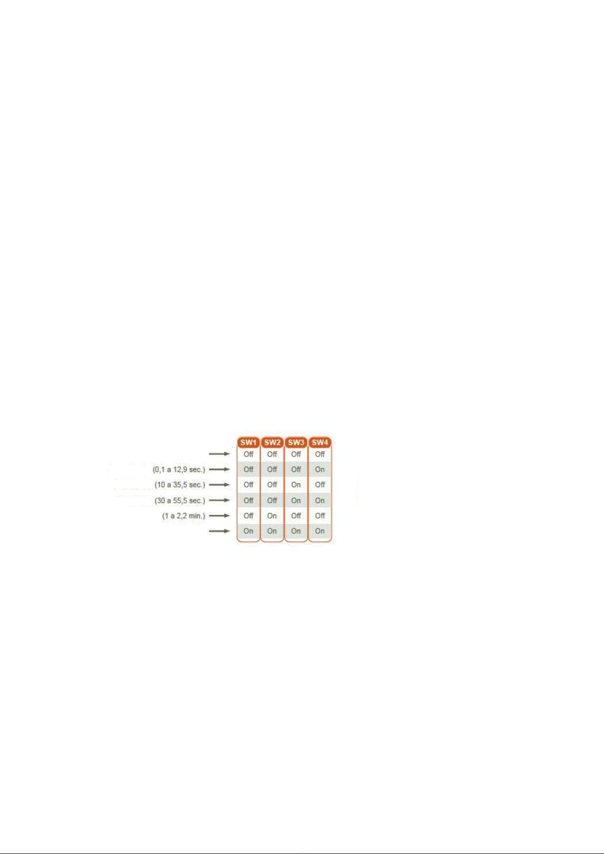
2. Set the Dip combination that etermines the type of operation that the relay will assume (fig. 3).
3. Receiver programming is starte by briefly pressing the “Enter” button. The re le will light up.
4. With the receiver on stan by, you only have to press the button of the transmitter to which you want to associate. The transmitter
button must be kept close until the LP0 le performs three cycles of flashing an fixe , (necessary process to correctly rea an
i entify the transmitter button). This operation coul take a few secon s.
5. Programming is confirme by briefly pressing the receiver's “Enter” button again or waiting 20 secon s. The re le will turn off.
Next relay. To program the next relay, the programming process must be restarte again from point 1. However, when the le of the
first relay lights up, briefly press Select, the new relay will be selecte an its correspon ing le will light up. From that moment on,
the rest of the process must simply be complete .
The memory is FIFO, so from the pairing with 5 transmitters, the next programme will occupy the memory that was allocate to
the first, another one woul replace the memory initially allocate to the secon an so on consecutively.
If a time operation is configure , the relay also stores the position of the “Time” potentiometer. The complete travel of the
potentiometer is establishe between the margins of the scale selecte in Dip. The specific potion of the potentiometer will be the
one that will establish the exact timing time.
FUNCTIONING.
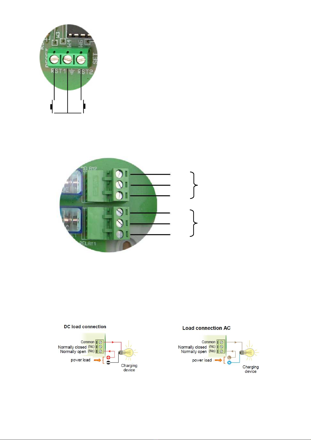
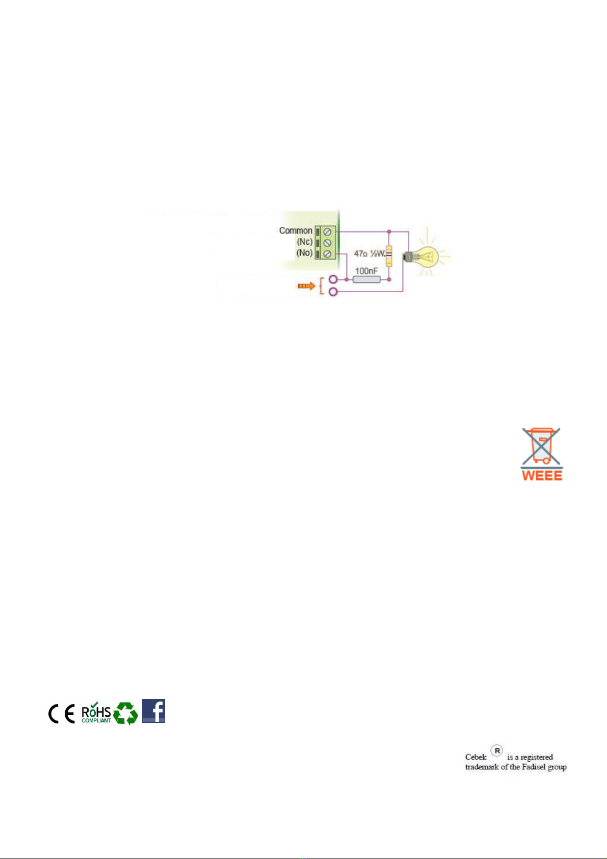
In the rest state, the receiver relay will be inactive, maintaining the connection between the “Common” an “Nc” contacts. When the
relay is activate , it will switch the connection of the contacts to internally link the “Common” with the “No” , allowing current to flow
to the loa .
Each relay will respon in epen ently to bistable, monostable or time operation, as programme .
Re et. When activating Reset, the relay will become inactive, aban oning any previous or er. As long as Reset is presse , the
relay will not respon to any or er from the transmitter.
Bie table. The transmitter button assumes the operation of a switch, activating or eactivating the relay alternately with each
press. As long as a new pulse oes not occur, the state in which the relay is foun will remain unchange .
Monoe table. As long as the transmitter button is kept close , the relay will be activate , eactivating when the button is
release .
Timer. The relay will be activate when the transmitter button is close . Timing, however, will start when the button is release , at
which point it will start an after which the relay will eactivate.
2
www.cebek.com - sat@fa isel.com
TL-602
Figure 3 Configuration Dip
* Response relay operation
monostable
timer
timer
timer
timer
biestable

RESET ACTIVATION
Reset relay 2
Reset relay 1
When activating “RST1” or “RST2”, the correspon ing relay will automatically
change to the off state, regar less of the or er it was previously executing.
The length of the cable use for each Reset input shoul be as short as
possible.
RELAY CONNECTION
The relay connection shoul not be consi ere as an output, it oes not provi e voltage.
Electrically isolate from the rest of the circuit, its function is to open or close its contacts to allow or interrupt the passage of an
electrical signal, as a common switch woul o on a light bulb.
common
NC
NC
NO
NO
Relay 2
Relay 1
Relay connection. Load control.
The relay connection shoul not be consi ere as an output, it oes not provi e voltage. Electrically isolate from the rest of the
circuit, its function is to open or close its contacts to allow or interrupt the passage of an electrical signal, as a common switch
woul o on a light bulb. The relay has three terminals: Common, Normally open at rest (NO), an Normally close at rest (NC).
One of the two loa power cables must be connecte irectly to the loa , the other must be inserte through the relay contacts,
typically between Common an NO, as specifie in the iagram in fig. 1, so that the relay internally cuts or allows the electrical
flow of the loa
3
www.cebek.com - sat@fa isel.com
TL-602
common

TL-602
Especially with in uctive loa s, a relay output may cause flickering, flickering, flickering, or malfunction. If this happens, it will be
necessary to install an anti-spark circuit between the two relay contacts use in the connection, which will ensure the absorption of
the peak current that causes the aforementione problem. Note fig. 2. If the loa connecte to the circuit relay is powere at 230 V.
apply a 100nF/400 V. capacitor an a 47 ohm ½ W resistor. If you have a 100nF type X2 capacitor (more effective), resistance will
not be necessary. In applications where the loa is powere at 230VAC, the installation will consi er only the con enser, without
the resistor. It shoul be teste with values between 10 nF an 47 nF until the fluctuation isappears.
4
INFORMATION REGARDING ENVIRONMENTAL PROTECTION
When this pro uct is no longer in use, it cannot be ispose of with normal househol waste, it must be taken to a
selective collection point for the recycling of electrical an electronic equipment. A symbol on the pro uct, the
instructions for use or the packaging in icates this. Materials are recyclable as marke . If you reuse, recycle or
otherwise use ol appliances you are making an important contribution towar s protecting the environment. Please
ask your local council which is the closest appropriate isposal point or lan fill to your home.
CONSIDERATIONS / WARRANTY
This kit is inten e for use by professionals, or users with a technical level or sufficient knowle ge, which allows them to evelop
the esire projects or applications by themselves. If it is use for e ucational use, its use an assembly un er the supervision
of teaching staff is recommen e . Cebek pro ucts have a 3-year guarantee from the ate of purchase. Incorrect assembly or
han ling is exclu e . We reserve the right to intro uce technical alterations. We o not take any responsibility for printing errors.
The technical ocumentation of this pro uct respon s to a transcription of that provi e by the manufacturer.
www.cebek.com - sat@fa isel.com
Fig 2 filter anti-relay fluctuations
230V AC load from 50W
power loa
Normally close
Normally open
Charging
evice
Table of contents
Other CEBEK Relay manuals
Popular Relay manuals by other brands

Pilz
Pilz PNOZ e1p operating manual

BERNSTEIN
BERNSTEIN SCR 2-W22-2.5-S Installation and operating instructions

Ice
Ice NPM800R user guide

Basler
Basler BE1-50/51B-229 instruction manual

Schweitzer Engineering Laboratories
Schweitzer Engineering Laboratories SEL-321-3 instruction manual

GE
GE IFC66A instructions