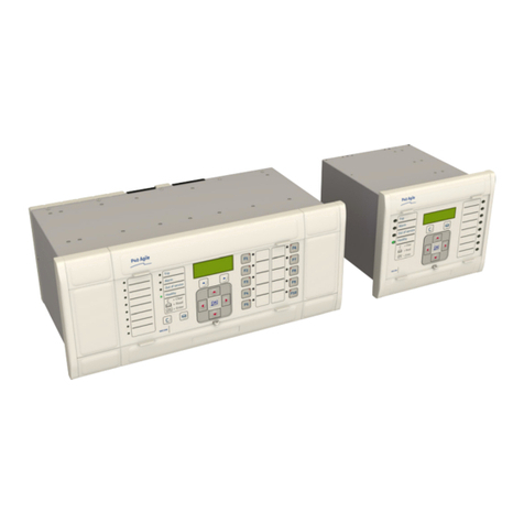
GE Masoneilan 469 Series User manual

GE Power Management 469 Motor Management Relay
i
TABLE OF CONTENTS
1. INTRODUCTION 1.1 OVERVIEW
1.1.1 DESCRIPTION .......................................................................................... 1-1
1.1.2 ORDER INFORMATION............................................................................ 1-4
1.1.3 OTHER ACCESSORIES ........................................................................... 1-4
1.2 SPECIFICATIONS
1.2.1 469 SPECIFICATIONS.............................................................................. 1-5
2. INSTALLATION 2.1 MECHANICAL
2.1.1 DESCRIPTION .......................................................................................... 2-1
2.1.2 PRODUCT IDENTIFICATION.................................................................... 2-2
2.1.3 INSTALLATION ......................................................................................... 2-3
2.1.4 UNIT WITHDRAWAL AND INSERTION.................................................... 2-4
2.1.5 TERMINAL LOCATIONS........................................................................... 2-6
2.2 ELECTRICAL
2.2.1 TYPICAL WIRING DIAGRAM.................................................................... 2-8
2.2.2 TYPICAL WIRING...................................................................................... 2-9
2.2.3 CONTROL POWER................................................................................... 2-9
2.2.4 PHASE CURRENT INPUTS.................................................................... 2-10
2.2.5 GROUND CURRENT INPUT................................................................... 2-10
2.2.6 DIFFERENTIAL CURRENT INPUTS....................................................... 2-12
2.2.7 VOLTAGE INPUTS.................................................................................. 2-13
2.2.8 DIGITAL INPUTS..................................................................................... 2-13
2.2.9 ANALOG INPUTS.................................................................................... 2-14
2.2.10 ANALOG OUTPUTS................................................................................ 2-14
2.2.11 RTD SENSOR CONNECTIONS.............................................................. 2-15
a DESCRIPTION ........................................................................................ 2-15
b REDUCED RTD LEAD NUMBER APPLICATION................................... 2-16
c TWO WIRE RTD LEAD COMPENSATION.............................................2-17
d GROUNDING OF RTDs .......................................................................... 2-17
2.2.12 OUTPUT RELAYS................................................................................... 2-18
2.2.13 DRAWOUT INDICATOR.......................................................................... 2-19
2.2.14 RS485 COMMUNICATIONS PORTS...................................................... 2-20
2.2.15 TYPICAL 2 SPEED MOTOR WIRING..................................................... 2-21
2.2.16 DIELECTRIC STRENGTH TESTING...................................................... 2-22
3. OPERATION 3.1 OVERVIEW
3.1.1 469 FACEPLATE....................................................................................... 3-1
3.1.2 DISPLAY.................................................................................................... 3-2
3.1.3 LED INDICATORS..................................................................................... 3-2
a 469 STATUS LED INDICATORS............................................................... 3-2
b MOTOR STATUS LED INDICATORS....................................................... 3-3
c OUTPUT RELAY LED INDICATORS........................................................ 3-3
3.1.4 RS232 PROGRAM PORT ......................................................................... 3-3
3.1.5 KEYPAD .................................................................................................... 3-4
3.1.6 ENTERING ALPHANUMERIC TEXT......................................................... 3-4
3.1.7 ENTERING +/– SIGNS.............................................................................. 3-4
3.2 SETPOINT ENTRY
3.2.1 PROCEDURE............................................................................................ 3-5

ii
469 Motor Management Relay GE Power Management
TABLE OF CONTENTS
4. SETPOINT
PROGRAMMING 4.1 OVERVIEW
4.1.1 TRIPS/ALARMS/BLOCKS DEFINED ........................................................ 4-1
a TRIPS ........................................................................................................4-1
b ALARMS .................................................................................................... 4-1
c BLOCK START.......................................................................................... 4-1
4.1.2 RELAY ASSIGNMENT PRACTICES......................................................... 4-2
4.1.3 SETPOINT MESSAGE MAP ..................................................................... 4-3
4.2 S1 469 SETUP
4.2.1 PASSCODE............................................................................................... 4-4
a FUNCTION ................................................................................................ 4-4
b ENABLING PASSCODE PROTECTION...................................................4-4
4.2.2 PREFERENCES........................................................................................ 4-5
4.2.3 SERIAL PORTS......................................................................................... 4-6
4.2.4 REAL TIME CLOCK...................................................................................4-6
4.2.5 DEFAULT MESSAGES ............................................................................. 4-7
a ADDING DEFAULT MESSAGES ..............................................................4-7
b REMOVING DEFAULT MESSAGES.........................................................4-7
4.2.6 MESSAGE SCRATCHPAD ....................................................................... 4-8
4.2.7 CLEAR DATA ............................................................................................ 4-9
4.2.8 INSTALLATION ....................................................................................... 4-10
4.3 S2 SYSTEM SETUP
4.3.1 CURRENT SENSING .............................................................................. 4-11
a FUNCTION .............................................................................................. 4-11
b EXAMPLES.............................................................................................. 4-12
4.3.2 VOLTAGE SENSING...............................................................................4-12
4.3.3 POWER SYSTEM.................................................................................... 4-13
4.3.4 SERIAL COMMUNICATION CONTROL ................................................. 4-13
4.3.5 REDUCED VOLTAGE ............................................................................. 4-14
4.4 S3 DIGITAL INPUTS
4.4.1 DESCRIPTION ........................................................................................ 4-16
4.4.2 ACCESS SWITCH...................................................................................4-16
4.4.3 TEST SWITCH......................................................................................... 4-16
4.4.4 EMERGENCY RESTART........................................................................ 4-16
4.4.5 REMOTE RESET..................................................................................... 4-16
4.4.6 STARTER STATUS.................................................................................4-17
4.4.7 ASSIGNABLE DIGITAL INPUTS............................................................. 4-17
4.4.8 DIGITAL INPUT FUNCTION: REMOTE ALARM.....................................4-18
4.4.9 DIGITAL INPUT FUNCTION: REMOTE TRIP.........................................4-18
4.4.10 DIGITAL INPUT FUNCTION: SPEED SWITCH TRIP.............................4-19
4.4.11 DIGITAL INPUT FUNCTION: LOAD SHED TRIP.................................... 4-19
4.4.12 DIGITAL INPUT FUNCTION: PRESSURE SWITCH ALARM .................4-19
4.4.13 DIGITAL INPUT FUNCTION: PRESSURE SWITCH TRIP ..................... 4-20
4.4.14 DIGITAL INPUT FUNCTION: VIBRATION SWITCH ALARM..................4-20
4.4.15 DIGITAL INPUT FUNCTION: VIBRATION SWITCH TRIP......................4-20
4.4.16 DIGITAL INPUT FUNCTION: DIGITAL COUNTER................................. 4-21
a FUNCTION .............................................................................................. 4-21
b EXAMPLE................................................................................................ 4-21
4.4.17 DIGITAL INPUT FUNCTION: TACHOMETER ........................................ 4-22
a FUNCTION .............................................................................................. 4-22
b EXAMPLE................................................................................................ 4-22
4.4.18 DIGITAL INPUT FUNCTION: GENERAL SWITCH A-D..........................4-23
4.4.19 DIGITAL INPUT FUNCTION: CAPTURE TRACE ................................... 4-23
4.4.20 DIGITAL INPUT FUNCTION: SIMULATE PRE-FAULT .......................... 4-23
4.4.21 DIGITAL INPUT FUNCTION: SIMULATE FAULT .................................. 4-23
4.4.22 DIGITAL INPUT FUNCTION: SIMULATE PRE-FAULT…FAULT ........... 4-23
4.5 S4 OUTPUT RELAYS
4.5.1 DESCRIPTION ........................................................................................ 4-24

GE Power Management 469 Motor Management Relay
iii
TABLE OF CONTENTS
4.5.2 RELAY RESET MODE ........................................................................... 4-24
a RESETTING THE 469............................................................................. 4-24
b EXAMPLE................................................................................................ 4-24
4.5.3 FORCE OUTPUT RELAY ....................................................................... 4-25
4.6 S5 THERMAL MODEL
4.6.1 MOTOR THERMAL LIMITS..................................................................... 4-26
4.6.2 469 THERMAL MODEL .......................................................................... 4-28
4.6.3 OVERLOAD CURVE SETUP ................................................................. 4-29
a FUNCTION .............................................................................................. 4-31
b CUSTOM OVERLOAD CURVE............................................................... 4-31
c VOLTAGE DEPENDENT OVERLOAD CURVE ...................................... 4-35
4.6.4 UNBALANCE BIAS.................................................................................. 4-42
4.6.5 MOTOR COOLING.................................................................................. 4-43
4.6.6 HOT/COLD CURVE RATIO..................................................................... 4-44
4.6.7 RTD BIAS ................................................................................................ 4-44
4.7 S6 CURRENT ELEMENTS
4.7.1 SHORT CIRCUIT..................................................................................... 4-46
4.7.2 OVERLOAD ALARM................................................................................ 4-47
4.7.3 MECHANICAL JAM................................................................................. 4-47
4.7.4 UNDERCURRENT................................................................................... 4-48
a FUNCTION .............................................................................................. 4-48
b EXAMPLE................................................................................................ 4-48
4.7.5 CURRENT UNBALANCE ........................................................................ 4-49
a FUNCTION .............................................................................................. 4-49
b EXAMPLE................................................................................................ 4-49
4.7.6 GROUND FAULT..................................................................................... 4-50
4.7.7 PHASE DIFFERENTIAL.......................................................................... 4-52
4.8 S7 MOTOR STARTING
4.8.1 ACCELERATION TIMER......................................................................... 4-53
4.8.2 START INHIBIT ....................................................................................... 4-54
a FUNCTION .............................................................................................. 4-54
b EXAMPLE................................................................................................ 4-54
4.8.3 JOGGING BLOCK ................................................................................... 4-55
a FUNCTION .............................................................................................. 4-55
b STARTS / HOUR ..................................................................................... 4-55
c TIME BETWEEN STARTS ...................................................................... 4-55
4.8.4 RESTART BLOCK................................................................................... 4-56
4.9 S8 RTD TEMPERATURE
4.9.1 RTD TYPES............................................................................................. 4-57
4.9.2 RTDS 1 TO 6 ........................................................................................... 4-58
4.9.3 RTDS 7 TO 10 ......................................................................................... 4-59
4.9.4 RTD 11..................................................................................................... 4-60
4.9.5 RTD 12..................................................................................................... 4-61
4.9.6 OPEN RTD SENSOR.............................................................................. 4-62
4.9.7 RTD SHORT/LOW TEMP........................................................................4-62
4.10 S9 VOLTAGE ELEMENTS
4.10.1 UNDERVOLTAGE................................................................................... 4-63
4.10.2 OVERVOLTAGE...................................................................................... 4-64
4.10.3 PHASE REVERSAL................................................................................. 4-64
4.10.4 FREQUENCY .......................................................................................... 4-65
4.11 S10 POWER ELEMENTS
4.11.1 POWER MEASUREMENT CONVENTIONS........................................... 4-66
4.11.2 POWER FACTOR.................................................................................... 4-67
4.11.3 REACTIVE POWER ................................................................................ 4-68
4.11.4 UNDERPOWER....................................................................................... 4-69
a FUNCTION .............................................................................................. 4-69
b EXAMPLE................................................................................................ 4-69

iv
469 Motor Management Relay GE Power Management
TABLE OF CONTENTS
4.11.5 REVERSE POWER .................................................................................4-70
4.11.6 TORQUE SETUP..................................................................................... 4-71
4.11.7 OVERTORQUE SETUP .......................................................................... 4-71
4.12 S11 MONITORING
4.12.1 TRIP COUNTER ...................................................................................... 4-72
4.12.2 STARTER FAILURE................................................................................ 4-72
4.12.3 CURRENT, KW, KVAR, KVA DEMAND..................................................4-74
4.12.4 PULSE OUTPUT ..................................................................................... 4-76
4.13 S12 ANALOG I/O
4.13.1 ANALOG OUTPUTS 1 TO 4.................................................................... 4-77
c ANALOG OUTPUT TABLE...................................................................... 4-78
4.13.2 ANALOG INPUTS 1-4.............................................................................. 4-79
a FUNCTION .............................................................................................. 4-80
b EXAMPLE 1............................................................................................. 4-80
c EXAMPLE 2............................................................................................. 4-80
4.13.3 ANALOG IN DIFF 1-2..............................................................................4-81
4.13.4 ANALOG IN DIFF 3-4..............................................................................4-82
4.14 S13 469 TESTING
4.14.1 SIMULATION MODE ............................................................................... 4-83
4.14.2 PRE-FAULT SETUP................................................................................ 4-84
4.14.3 FAULT SETUP......................................................................................... 4-85
4.14.4 TEST OUTPUT RELAYS......................................................................... 4-86
4.14.5 TEST ANALOG OUTPUT........................................................................ 4-86
4.14.6 COMM PORT MONITOR......................................................................... 4-87
4.14.7 MULTILIN USE ONLY ............................................................................. 4-87
4.15 S14 TWO-SPEED MOTOR
4.15.1 DESCRIPTION ........................................................................................ 4-88
4.15.2 SPEED2 O/L SETUP...............................................................................4-88
4.15.3 SPEED2 UNDERCURRENT ................................................................... 4-90
4.15.4 SPEED2 ACCELERATION...................................................................... 4-91
5. ACTUAL VALUES 5.1 OVERVIEW
5.1.1 ACTUAL VALUES MESSAGES ................................................................5-1
5.2 A1 STATUS
5.2.1 MOTOR STATUS ...................................................................................... 5-2
5.2.2 LAST TRIP DATA ...................................................................................... 5-3
5.2.3 ALARM STATUS ....................................................................................... 5-5
5.2.4 START BLOCKS........................................................................................ 5-7
5.2.5 DIGITAL INPUTS....................................................................................... 5-8
5.2.6 REAL TIME CLOCK...................................................................................5-8
5.3 A2 METERING DATA
5.3.1 CURRENT METERING ............................................................................. 5-9
5.3.2 TEMPERATURE...................................................................................... 5-10
5.3.3 VOLTAGE METERING............................................................................ 5-11
5.3.4 SPEED..................................................................................................... 5-11
5.3.5 POWER METERING ...............................................................................5-12
5.3.6 TORQUE ALARM MESSAGE ................................................................. 5-12
5.3.7 DEMAND METERING ............................................................................. 5-13
5.3.8 ANALOG INPUTS.................................................................................... 5-14
5.3.9 PHASORS ............................................................................................... 5-15
5.4 A3 LEARNED DATA
5.4.1 MOTOR STARTING ................................................................................ 5-17
5.4.2 AVERAGE MOTOR LOAD ...................................................................... 5-17

GE Power Management 469 Motor Management Relay
v
TABLE OF CONTENTS
5.4.3 RTD MAXIMUMS..................................................................................... 5-18
5.4.4 ANALOG IN MIN/MAX.............................................................................5-19
5.5 A4 MAINTENANCE
5.5.1 TRIP COUNTERS.................................................................................... 5-20
5.5.2 GENERAL COUNTERS........................................................................... 5-22
5.5.3 TIMERS ................................................................................................... 5-22
5.6 A5 EVENT RECORDER
5.6.1 EVENT01 TO EVENT40.......................................................................... 5-23
5.7 A6 PRODUCT INFO
5.7.1 469 MODEL INFO.................................................................................... 5-26
5.7.2 CALIBRATION INFO ............................................................................... 5-26
5.8 DIAGNOSTICS
5.8.1 DIAGNOSTIC MESSAGES FOR OPERATORS..................................... 5-27
a EXAMPLE................................................................................................ 5-27
5.8.2 FLASH MESSAGES................................................................................ 5-28
6. COMMUNICATIONS 6.1 MODBUS COMMUNICATIONS
6.1.1 ELECTRICAL INTERFACE ....................................................................... 6-1
6.1.2 MODBUS RTU PROTOCOL...................................................................... 6-1
6.1.3 DATA FRAME FORMAT AND DATA RATE.............................................. 6-1
6.1.4 DATA PACKET FORMAT.......................................................................... 6-2
6.1.5 CRC-16 ALGORITHM................................................................................ 6-3
6.1.6 TIMING ...................................................................................................... 6-3
6.2 SUPPORTED MODBUS FUNCTIONS
6.2.1 OVERVIEW................................................................................................ 6-4
6.2.2 FUNCTION CODES 01/02: READ RELAY COIL / DIGITAL INPUT STATUS
6-4
a FUNCTION 01 ........................................................................................... 6-4
b FUNCTION 02 ........................................................................................... 6-4
c MESSAGE FORMAT AND EXAMPLE, FUNCTION 01.............................6-5
d MESSAGE FORMAT AND EXAMPLE, FUNCTION 02............................. 6-6
6.2.3 FUNCTION CODES 03/04: READ SETPOINTS/ACTUAL VALUES......... 6-8
6.2.4 FUNCTION CODE 05: EXECUTE OPERATION....................................... 6-9
6.2.5 FUNCTION CODE 06: STORE SINGLE SETPOINT ..............................6-10
6.2.6 FUNCTION CODE 07: READ DEVICE STATUS ....................................6-11
6.2.7 FUNCTION CODE 08: LOOPBACK TEST.............................................. 6-12
6.2.8 FUNCTION CODE 16: STORE MULTIPLE SETPOINTS........................6-13
6.2.9 FUNCTION CODE 16: PERFORMING COMMANDS ............................. 6-14
6.3 ERROR RESPONSES
6.3.1 DESCRIPTION ........................................................................................ 6-15
6.4 MEMORY MAP
6.4.1 MEMORY MAP INFORMATION.............................................................. 6-16
6.4.2 USER DEFINABLE MEMORY MAP AREA.............................................6-16
6.4.3 EVENT RECORDER ............................................................................... 6-17
6.4.4 WAVEFORM CAPTURE.......................................................................... 6-17
6.4.5 469 MEMORY MAP................................................................................. 6-18
6.4.6 469 MEMORY MAP FORMAT CODES................................................... 6-61
7. TESTING 7.1 OVERVIEW
7.1.1 TEST SETUP............................................................................................. 7-1

vi
469 Motor Management Relay GE Power Management
TABLE OF CONTENTS
7.2 HARDWARE FUNCTIONAL TESTING
7.2.1 PHASE CURRENT ACCURACY TEST.....................................................7-2
7.2.2 VOLTAGE INPUT ACCURACY TEST....................................................... 7-2
7.2.3 GROUND (1A/5A) AND DIFFERENTIAL ACCURACY TEST ................... 7-3
a 5 A INPUT.................................................................................................. 7-3
b 1 A INPUT.................................................................................................. 7-3
7.2.4 GE POWER MANAGEMENT 50:0.025 GROUND ACCURACY TEST.....7-4
7.2.5 RTD ACCURACY TEST ............................................................................ 7-4
7.2.6 DIGITAL INPUTS AND TRIP COIL SUPERVISION.................................. 7-6
7.2.7 ANALOG INPUTS AND OUTPUTS...........................................................7-6
a 4-20 mA ..................................................................................................... 7-6
b 0-1 mA ....................................................................................................... 7-7
7.2.8 OUTPUT RELAYS.....................................................................................7-8
7.3 ADDITIONAL FUNCTIONAL TESTING
7.3.1 OVERLOAD CURVE TEST ....................................................................... 7-9
7.3.2 POWER MEASUREMENT TEST ............................................................7-10
7.3.3 UNBALANCE TEST.................................................................................7-11
7.3.4 VOLTAGE PHASE REVERSAL TEST .................................................... 7-12
7.3.5 SHORT CIRCUIT TEST........................................................................... 7-13
8. 469 PC SOFTWARE 8.1 INSTALLATION/UPGRADE
8.1.1 DESCRIPTION .......................................................................................... 8-1
8.1.2 HARDWARE & SOFTWARE REQUIREMENTS.......................................8-1
8.1.3 CHECKING IF INSTALLATION/UPGRADE IS REQUIRED......................8-2
8.1.4 INSTALLING/UPGRADING 469PC ........................................................... 8-3
8.2 CONFIGURATION
8.2.1 STARTUP & COMMUNICATIONS CONFIGURATION.............................8-4
8.3 USING 469PC
8.3.1 SAVING SETPOINTS TO A FILE..............................................................8-5
8.3.2 469 FIRMWARE UPGRADES ................................................................... 8-6
8.3.3 LOADING SETPOINTS FROM A FILE......................................................8-7
8.3.4 ENTERING SETPOINTS........................................................................... 8-8
8.3.5 UPGRADING SETPOINT FILES TO NEW REVISION.............................. 8-9
8.3.6 PRINTING SETPOINTS & ACTUAL VALUES.........................................8-10
a SETPOINTS............................................................................................. 8-10
b ACTUAL VALUES.................................................................................... 8-10
8.3.7 TRENDING .............................................................................................. 8-11
8.3.8 WAVEFORM CAPTURE.......................................................................... 8-13
8.3.9 PHASORS ............................................................................................... 8-15
8.3.10 EVENT RECORDING.............................................................................. 8-16
8.3.11 TROUBLESHOOTING............................................................................. 8-17
A. APPENDIX A A.1 COMMISSIONING
A.1.1 COMMISSIONING SUMMARY..................................................................A-1
B. APPENDIX B B.1 TWO-PHASE CT CONFIGURATION
B.1.1 DESCRIPTION ..........................................................................................B-1

GE Power Management 469 Motor Management Relay
vii
TABLE OF CONTENTS
C. APPENDIX C C.1 SELECTION OF COOL TIME CONSTANTS
C.1.1 DESCRIPTION ..........................................................................................C-1
C.1.2 EXAMPLE..................................................................................................C-1
D. APPENDIX D D.1 CURRENT TRANSFORMERS
D.1.1 GROUND FAULT CTS FOR 50:0.025 A ...................................................D-1
D.1.2 GROUND FAULT CTS FOR 5 A SECONDARY CT..................................D-2
D.1.3 PHASE CTS...............................................................................................D-3
E. APPENDIX E E.1 FIGURES AND TABLES
E.1.1 LIST OF FIGURES ....................................................................................E-1
E.1.2 LIST OF TABLES.......................................................................................E-3
F. APPENDIX F F.1 EU DECLARATION OF CONFORMITY
G. WARRANTY G.1 WARRANTY INFORMATION
G.1.1 WARRANTY ..............................................................................................G-1


GE Power Management 469 Motor Management Relay 1-1
1 INTRODUCTION 1.1 OVERVIEW
1
1 INTRODUCTION 1.1 OVERVIEW 1.1.1 DESCRIPTION
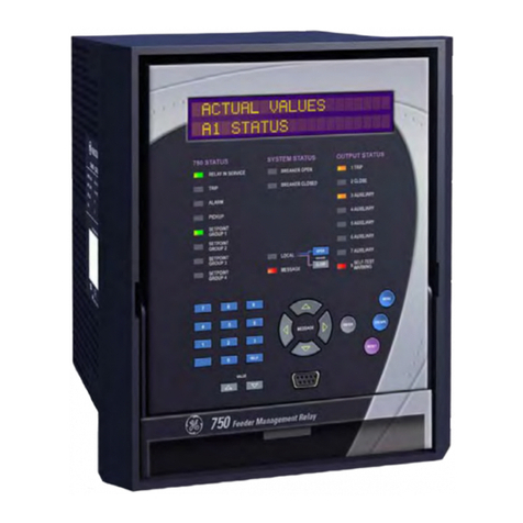
The 469 Motor Management Relay is a microprocessor based relay designed for the protection and manage-
ment of medium and large horsepower motors and driven equipment. The 469 is equipped with six output
relays for trips, alarms, and start blocks. Motor protection, fault diagnostics, power metering, and RTU func-
tions are integrated into one economical drawout package. The single-line diagram below illustrates the 469
functionality using ANSI (American National Standards Institute) device numbers.
Figure 1–1: SINGLE LINE DIAGRAM
Typical applications include:
• Pumps • Fans • Compressors
•Mills •Shredders •Extruders
• Debarkers • Refiners • Cranes
• Conveyors • Chillers • Crushers
•Blowers

1-2 469 Motor Management Relay GE Power Management
1.1 OVERVIEW 1 INTRODUCTION
1Some of the protection highlights are detailed here; a complete list is shown below. Four assignable digital
inputs may be configured for a number of different features including tachometer or generic trip and alarm with
a programmable name. The thermal model incorporates unbalance biasing, RTD feedback, and exponential
cooling. In addition to the 15 standard overload curves, there is a custom curve feature and a curve specifically
designed for the starting of high inertia loads, when the acceleration time exceeds the safe stall time. A second
overload curve is provided for two-speed motors. Ground faults or earth leakage as low as 0.25 A may be
detected using the GE Power Management 50:0.025 Ground CT. CT inputs for phase differential protection are
also provided. The 12 RTD inputs provided may be individually field programmed for different RTD types. Volt-
age transformer inputs allow for numerous protection features based on voltage and power quantities. Four
4 to 20 mA analog inputs may be used for tripping and alarming on any transducer input such as vibration,
pressure, flow, etc.
Figure 1–2: PROTECTION FEATURES
51 Overload
86 Overload Lockout
66 Starts/Hour & Time Between Starts
Restart Block (Anti-Backspin Timer)
50 Short Circuit & Short Circuit Backup
Mechanical Jam
37
32
Undercurrent/Underpower
Reverse Power
46 Current Unbalance
50G/51G Ground Fault & Ground Fault Backup
87 Differential
Acceleration
49 Stator RTD
38 Bearing RTD
Other RTD & Ambient RTD
Open RTD Alarm
Short/Low RTD
27/59 Undervoltage/Overvoltage
47 Phase Reversal
81 Frequency
Reactive Power
55/78 Power Factor
Analog Input
Demand Alarm: A kW kvar kVA
SR469 Self-Test, Service
Trip Coil Supervision
Welded Contactor
Breaker Failure
Remote Switch
14 Speed Switch & Tachometer Trip
Load Shed Switch
Pressure Switch
Vibration Switch
19 Reduced Voltage Start
48
Over Torque
Remote Start/Stop
PROCTLA5.CDR
Incomplete Sequence (Reduced Voltage Start)
Forced Relay Operation

GE Power Management 469 Motor Management Relay 1-3
1 INTRODUCTION 1.1 OVERVIEW
1
Fault diagnostics are provided through pretrip data, event record, trace memory, and statistics. Prior to issuing
a trip, the 469 takes a snapshot of the measured parameters and stores them with the cause of the trip. This
pre-trip data may be viewed using the key before the trip is reset, or by accessing the A1 STATUS /
LAST TRIP DATA actual values. The 469 event recorder stores up to 40 time and date stamped events including
the pre-trip data. Each time a trip occurs, the 469 stores a trace of 8 cycles pre-trip and 8 cycles post-trip for all
measured AC quantities. Trip counters record the number of occurrences of each type of trip. Minimum and
maximum values for RTDs and analog inputs are also recorded. These features enable the operator to pinpoint
a problem quickly and with certainty.
Power metering is built into the 469 as a standard feature. The table below outlines the metered parameters
available either through the front panel or communications ports.
The 469 is equipped with 3 fully functional and independent communications ports. The front panel RS232 port
may be used for 469 setpoint programming, local interrogation or control, and upgrading of 469 firmware. The
Computer RS485 port may be connected to a PLC, DCS, or PC based user interface program. The Auxiliary
RS485 port may be used for redundancy or simultaneous interrogation and/or control from a second PLC,
DCS, or PC software.
There are also four 4 to 20 mA or 0 to 1 mA (as specified with order) transducer outputs that may be assigned
to any measured parameter. The range of these outputs is scalable.
Additional features are outlined in the table below.
Table 1–1: METERING AND ADDITIONAL FEATURES
METERING ADDITIONAL FEATURES
Voltage Drawout case (for ease of maintenance/testing)
Current and amps demand Reduced voltage starting control for single transition
Real power, kW demand, kW power consumption Trip coil supervision
Apparent power and kVA demand Flash memory for easy firmware updates
Reactive power, kvar demand, kvar consumption/
generation
Frequency
Power Factor
RTD
Speed in RPM with a key phasor input
User-programmable analog inputs
NEXT

1-4 469 Motor Management Relay GE Power Management
1.1 OVERVIEW 1 INTRODUCTION
11.1.2 ORDER INFORMATION
All 469 features are standard; there are no options. The phase CT secondaries, control power, and analog out-
put range must be specified at the time of order. The 469 differential CT inputs are field programmable for CTs
with 1 A or 5 A secondaries. There are two ground CT inputs, one for the GE Power Management 50:0.025
core balance CT and one for a ground CT with a 1 A or 5 A secondary, also field programmable. The VT inputs
will accommodate VTs in either a delta or wye configuration. The output relays are always non-failsafe with the
exception of the service relay. The 469PC software is provided with each unit. A metal demo case may be
ordered for demonstration or testing purposes.
Figure 1–3: 469 ORDER CODES
Additional accessories are listed in the following section.
1.1.3 OTHER ACCESSORIES
• 469PC Software: Provided free with each relay
•DEMO: Metal Carry Case in which 469 unit may be mounted
•SR 19-1 PANEL: Single cutout 19" panel
•SR 19-2 PANEL: Dual cutout 19" panel
•SCI MODULE: RS232 to RS485 converter box designed for harsh industrial environments
•Phase CT: 50, 75, 100, 150, 200, 250, 300, 350, 400, 500, 600, 750, 1000
•HGF3, HGF5, HGF8: For sensitive ground detection on high resistance grounded systems.
• 469 1" Collar: For shallow switchgear, reduces the depth of the relay by 1 #3/8"
• 469 3" Collar: For shallow switchgear, reduces the depth of the relay by 3"
•Optional Mounting Kit: Additional mounting support 1819-0030
469
469 Basic unit
P1
P5
1A phase CT secondaries
5A phase CT secondaries
LO
HI
DC: 25-60 V; AC: 20-48 V @ 48-62 Hz
DC: 90-300 V; AC: 70-265 V @ 48-62 Hz
A1
A20
0-1 mA analog outputs
4-20 mA analog outputs
***

GE Power Management 469 Motor Management Relay 1-5
1 INTRODUCTION 1.2 SPECIFICATIONS
1
1.2 SPECIFICATIONS 1.2.1 469 SPECIFICATIONS
POWER SUPPLY
Options: LO / HI (must be specified with order)
Range: LO: DC: 20 to 60 V DC
AC: 20 to 48 VAC at 48 to 62 Hz
HI: DC: 90 to 300 V DC
AC: 70 to 265 V AC at 48 to 62 Hz
Power: 45 VA (max), 25 VA typical
Proper operation time without supply voltage: 30 ms
PHASE CURRENT INPUTS
CT Primary: 1 to 5000 A
CT Secondary: 1 A or 5 A (must be specified with order)
Burden: Less than 0.2 VA at rated load
Conversion Range: 0.05 to 20 ×CT
Accuracy: at < 2 x CT: ± 0.5% of 2 ×CT
at ≥2 x CT: ± 1% of 20 ×CT
CT Withstand: 1 second @ 80 ×rated current
2 seconds @ 40 ×rated current
continuous @ 3 ×rated current
GROUND CURRENT INPUTS
CT Primary: 1 to 5000 A
CT Secondary: 1 A or 5 A (setpoint)
Burden: < 0.2 VA at rated load for 1 A or 5 A
< 0.25 VA for 50:0.025 @ 25 A
Conversion Range: 0.02 to 1 ×CT primary Amps
Accuracy: ± 0.5% of 1 ×CT for 5 A
± 0.5% of 5 ×CT for 1 A
± 0.125 A for 50:0.025
CT Withstand: 1 second @ 80 ×rated current
2 seconds @ 40 ×rated current
continuous @ 3 ×rated current
DIFFERENTIAL PHASE CURRENT INPUTS
CT Primary: 1 to 5000A
CT Secondary: 1 A or 5 A (setpoint)
Burden: Less than 0.2 VA at rated load
Conversion Range: 0.02 to 1 ×CT
Accuracy: ±0.5% of 1 ×CT for 5 A
±0.5% of 5 ×CT for 1 A
CT Withstand: 1 second @ 80 ×rated current
2 seconds @ 40 ×rated current
continuous @ 3 ×rated current
VOLTAGE INPUTS
VT Ratio: 1.00 to 150.00:1 in steps of 0.01
VT Secondary: 273 V AC (full scale)
Conversion Range: 0.05 to 1.00 ×full scale
Accuracy: ±0.5% of full scale
Max. Continuous: 280 V AC
Burden: > 500 kΩ
DIGITAL INPUTS
Inputs: 9 opto-isolated inputs
External Switch: dry contact < 800 Ω, or
open collector NPN transistor from sen-
sor; 6 mA sinking from internal 4 KΩpull-
up at 24 V DC with Vce < 4 V DC
469 Sensor Supply: +24 V DC at 20 mA max.
RTD INPUTS
RTDs: 3 wire type:100 ΩPlatinum (DIN.43760)
100 ΩNickel
120 ΩNickel
10 ΩCopper
RTD Sensing Current: 5mA
Isolation: 36 Vpk
(isolated with analog inputs and outputs)
Range: –50 to +250°C
Accuracy: ±2°C
Lead Resistance: 25 ΩMax per lead for Pt and Ni type
3ΩMax per lead for Cu type
No Sensor: >1000 Ω
Short/Low Alarm: < –50°C
TRIP COIL SUPERVISION
Applicable Voltage: 20 to 300 V DC / V AC
Trickle Current: 2 to 5 mA
ANALOG CURRENT INPUTS
Current Inputs: 0 to 1 mA, 0 to 20mA or 4 to 20 mA
(setpoint)
Input Impedance: 226 Ω±10%
Conversion Range: 0 to 21 mA
Accuracy: ±1% of full scale
Type: passive
Analog Input Supply: +24 V DC at 100 mA max.
Response Time: ≤ 100 ms
COMMUNICATIONS PORTS
RS232 Port: 1, Front Panel, non-isolated
RS485 Ports: 2, Isolated together @ 36 Vpk
Baud Rates: RS485: 300, 1200, 2400, 4800, 9600,
19200
RS232: 9600
Parity: None, Odd, Even
Protocol: Modbus®RTU / half duplex

1-6 469 Motor Management Relay GE Power Management
1.2 SPECIFICATIONS 1 INTRODUCTION
1ANALOG CURRENT OUTPUT
Type: Active
Range: 4 to 20 mA, 0 to 1 mA
(must be specified with order)
Accuracy: ±1% of full scale
4 to 20 mA maximum load: 1200 Ω
0 to 1 mA maximum load: 10 kΩ
Isolation: 36 Vpk
(Isolated with RTDs and Analog Inputs)
4 Assignable Outputs:
phase A current
phase B current
phase C current
3 phase average current
ground current
phase AN (AB) voltage
phase BN (BC) voltage
phase CN (CA) voltage
3 phase average voltage
hottest stator RTD
hottest bearing RTD
hottest other RTD
RTD # 1 to 12
Power factor
3 phase Real power (kW)
3 phase Apparent power (kVA)
3 phase Reactive power (kvar)
Thermal Capacity Used
Relay Lockout Time
Current Demand
kvar Demand
kW Demand
kVA Demand
Motor Load
Torque
OVERLOAD / STALL PROTECTION /
THERMAL MODEL
Overload Curves:15 Standard Overload Curves, Custom
Curve, Voltage Dependent Custom
Curve for high inertia starting (all curves
time out against average phase current)
Curve Biasing: Phase Unbalance
Hot/Cold Curve Ratio
Stator RTD
Running Cool rate
Stopped Cool Rate
Line Voltage
Overload Pickup: 1.01 to 1.25 (for service factor)
Pickup Accuracy: as per Phase Current Inputs
Timing Accuracy: ±100 ms or ±2% of total time
Elements: Trip and Alarm
OUTPUT RELAYS
Configuration: 6 Electromechanical Form C
Contact Material: silver alloy
Operate Time: 10 ms
Max ratings for 100000 operations:
TERMINALS
Low Voltage (A, B, C, D terminals): 12 AWG max.
High Voltage (E, F, G, H terminals): #8 ring lug, 10 AWG
wire standard
PHASE SHORT CIRCUIT
Pickup Level: 4.0 to 20.0 ×CT primary in steps of 0.1
of any one phase
Time Delay: 0 to 1000 ms in steps of 10
Pickup Accuracy: as per Phase Current Inputs
Timing Accuracy: +50 ms
Elements: Trip
MECHANICAL JAM
Pickup Level: 1.01 to 3.00 ×FLA in steps of 0.01 of any
one phase, blocked on start
Time Delay: 1 to 30 s in steps of 1
Pickup Accuracy: as per Phase Current Inputs
Timing Accuracy: ±0.5 s or ±0.5% of total time
Elements: Trip
UNDERCURRENT
Pickup Level: 0.10 to 0.95 ×CT primary in steps of
0.01 of any one phase
Time Delay: 1 to 60 s in steps of 1
Block From Start: 0 to 15000 s in steps of 1
Pickup Accuracy: as per Phase Current Inputs
Timing Accuracy: ±0.5 s or ±0.5% of total time
Elements: Trip and Alarm
VOLTAGE MAKE/CARRY BREAK MAX.
LOAD
CONTINUOUS 0.2s
DC
RESISTIVE 30 V 10 A 30 A 10 A 300 W
125 V 10 A 30 A 0.5 A 62.5 W
250 V 10 A 30 A 0.3 A 75 W
DC
INDUCTIVE
L/R=40ms
30 V 10 A 30 A 5 A 150 W
125 V 10 A 30 A 0.25 A 31.3 W
250 V 10 A 30 A 0.15 A 37.5 W
AC
RESISTIVE 120 V 10 A 30 A 10 A 2770 VA
250 V 10 A 30 A 10 A 2770 VA
AC
INDUCTIVE
P.F.=0.4
120 V 10 A 30 A 4 A 480 VA
250 V 10 A 30 A 3 A 750 VA

GE Power Management 469 Motor Management Relay 1-7
1 INTRODUCTION 1.2 SPECIFICATIONS
1
CURRENT UNBALANCE
Unbalance: I2/I
1if Iavg > FLA
I2/I
1×Iavg /FLAifI
avg < FLA
Range: 0 to 100% UB in steps of 1
Pickup Level: 4 to 40% UB in steps of 1
Time Delay: 1 to 60 s in steps of 1
Pickup Accuracy: ±2%
Timing Accuracy: ±0.5 s or ± 0.5% of total time
Elements: Trip and Alarm
GROUND INSTANTANEOUS
Pickup Level: 0.1 to 1.0 ×CT primary in steps of 0.01
Time Delay: 0 to 1000 ms in steps of 10
Pickup Accuracy: as per Ground Current Input
Timing Accuracy: +50 ms
Elements: Trip and Alarm
PHASE DIFFERENTIAL INSTANTANEOUS
Pickup Level: 0.05 to 1.0 ×CT primary in steps of 0.01
of any one phase
Time Delay: 0 to 1000 ms in steps of 10
Pickup Accuracy: as per Phase Differential Current Inputs
Timing Accuracy: +50 ms
Elements: Trip
ACCELERATION TIMER
Pickup: transition of no phase current to > over-
load pickup
Dropout: when current falls below overload pickup
Time Delay: 1.0 to 250.0 s in steps of 0.1
Timing Accuracy: ±100 ms or ± 0.5% of total time
Elements: Trip
JOGGING BLOCK
Starts/Hour: 1 to 5 in steps of 1
Time Between Starts: 1 to 500 min.
Timing Accuracy: ±0.5 s or ± 0.5% of total time
Elements: Block
RESTART BLOCK
Time Delay: 1 to 50000 s in steps of 1
Timing Accuracy: ±0.5 s or ± 0.5% of total time
Elements: Block
RTD
Pickup: 1 to 250°C in steps of 1
Pickup Hysteresis:2°C
Time Delay: 3 s
Elements: Trip and Alarm
UNDERVOLTAGE
Pickup Level:
Motor Starting: 0.60 to 0.99 × Rated in steps of 0.01
Motor Running: 0.60 to 0.99 × Rated in steps of 0.01
of any one phase
Time Delay: 0.1 to 60.0 s in steps of 0.1
Pickup Accuracy: as per Voltage Inputs
Timing Accuracy: <100 ms or ±0.5% of total time
Elements: Trip and Alarm
OVERVOLTAGE
Pickup Level: 1.01 to 1.10 × Rated in steps of 0.01 of
any one phase
Time Delay: 0.1 to 60.0 s in steps of 0.1
Pickup Accuracy: as per Voltage Inputs
Timing Accuracy: ±100 ms or ±0.5% of total time
Elements: Trip and Alarm
VOLTAGE PHASE REVERSAL
Configuration: ABC or ACB phase rotation
Timing Accuracy: 500 to 700 ms
Elements: Trip
FREQUENCY
Required Voltage:> 30% of full scale in Phase A
Overfrequency Pickup: 25.01 to 70.00 in steps of 0.01
Underfrequency Pickup: 20.00 to 60.00 in steps of 0.01
Accuracy: ±0.02 Hz
Time Delay: 0.1 to 60.0 s in steps of 0.1
Timing Accuracy: <100 ms or ±0.5% of total time
Elements: Trip and Alarm
REDUCED VOLTAGE START
Transition Level: 25 to 300% FLA in steps of 1
Transition Time: 1 to 250 s in steps of 1
Transition Control: Current, Timer, Current and Timer
REMOTE SWITCH
Configurable: Assignable to Digital Inputs1 to 4
Timing Accuracy: 100 ms max.
Elements: Trip and Alarm
SPEED SWITCH
Configurable: Assignable to Digital Inputs1 to 4
Time Delay: 1.0 to 250.0 s in steps of 0.1
Timing Accuracy: 100 ms max.
Elements: Trip
LOAD SHED
Configurable: Assignable to Digital Inputs1 to 4
Timing Accuracy: 100 ms max.
Elements: Trip

1-8 469 Motor Management Relay GE Power Management
1.2 SPECIFICATIONS 1 INTRODUCTION
1PRESSURE SWITCH
Configurable: Assignable to Digital Inputs1 to 4
Time Delay: 0.1 to 100.0 s in steps of 0.1
Block From Start: 0 to 5000 s in steps of 1
Timing Accuracy: ±100 ms or ±0.5% of total time
Elements: Trip and Alarm
VIBRATION SWITCH
Configurable: Assignable to Digital Inputs1 to 4
Time Delay: 0.1 to 100.0 s in steps of 0.1
Timing Accuracy: ±100 ms or ±0.5% of total time
Elements: Trip and Alarm
DIGITAL COUNTER
Configurable: Assignable to Digital Inputs1 to 4
Counting Frequency: ≤50 times a second
Range: 0 to 1 000 000 000
Elements: Alarm
TACHOMETER
Configurable: Assignable to Digital Inputs1 to 4
RPM Measurement: 100 to 7200 RPM
Duty Cycle of Pulse: > 10%
Elements: Trip and Alarm
GENERAL PURPOSE SWITCH
Configurable: Assignable Digital Inputs1 to 4
Time Delay: 0.1 to 5000.0 s in steps of 0.1
Block From Start: 0 to 5000 s in steps of 1
Timing Accuracy: ±100 ms or ±0.5% of total time
Elements: Trip and Alarm
POWER FACTOR
Range: 0.01 lead or lag to 1.00
Pickup Level: 0.99 to 0.05 in steps of 0.01, Lead & Lag
Time Delay: 0.2 to 30.0 s in steps of 0.1
Block From Start: 0 to 5000 s in steps of 1
Pickup Accuracy: ±0.02
Timing Accuracy: ±100 ms or ±0.5% of total time
Elements: Trip and Alarm
3 PHASE REAL POWER
Range: 0 to ±99999 kW
Underpower Pickup: 1 to 25000 kW in steps of 1
Time Delay: 1 to 30 s in steps of 1
Block From Start: 0 to 15000 s in steps of 1
Pickup Accuracy:
±1% of × 2 × CT × VT × VTfull scale at Iavg < 2 × CT
±1.5% of × 20 × CT × VT × VTfull scale at Iavg > 2 × CT
Timing Accuracy: ±0.5 s or ±0.5% of total time
Elements: Trip and Alarm
3 PHASE APPARENT POWER
Range: 0 to 65535 kVA
Accuracy:
±1% of × 2 × CT × VT × VTfull scale @ Iavg < 2 × CT
±1.5% of × 20 × CT × VT × VTfull scale @ Iavg > 2 × CT
3 PHASE REACTIVE POWER
Range: 0 to ±99999 kvar
Pickup Level: ±1 to 25000 kvar in steps of 1
Time Delay: 0.2 to 30.0 s in steps of 0.1
Block From Start: 0 to 5000 s in steps of 1
Pickup Accuracy:
±1% of × 2 × CT × VT × VTfull scale @ Iavg < 2 × CT
±1.5% of × 20 × CT × VT × VTfull scale @ Iavg > 2 × CT
Timing Accuracy: ±100ms or ± 0.5% of total time
Elements: Trip and Alarm
OVER TORQUE
Pickup Level: 1.0 to 999999.9 Nm/ft·lb in steps of 0.1;
torque unit is selectable under torque
setup
Time Delay: 0.2 to 30.0 s in steps of 0.1
Pickup Accuracy: ±2.0%
Time Accuracy: ±100 ms or 0.5% of total time
Elements: Alarm (INDUCTION MOTORS ONLY)
METERED REAL POWER CONSUMPTION
Description: Continuous total of real power
consumption.
Range: 0 to 2000000.000 MW·hours.
Timing Accuracy: ±0.5%
Update Rate: 5 seconds
METERED REACTIVE POWER CONSUMPTION
Description: Continuous total of reactive power
consumption.
Range: 0 to 2000000.000 Mvar·hours
Timing Accuracy: ±0.5%
3
3
33
33

GE Power Management 469 Motor Management Relay 1-9
1 INTRODUCTION 1.2 SPECIFICATIONS
1
FUSE
Hi-Volt:
Current Rating: 2 A
Type: 5 × 20mm Slo-Blo Littelfuse
High Breaking Capacity
Model#: 215002
Lo-Volt:
Current Rating: 3.15 A
Type: 5 × 20mm Slo-Blo Littelfuse
High Breaking Capacity
Model#: 2153.15
External fuse must be used if the supply volt-
age exceeds 250 V.
DEMAND
Metered Values: Maximum Phase Current
3 Phase Real Power
3 Phase Apparent Power
3 Phase Reactive Power
Measurement Type: Rolling Demand
Demand Interval: 5 to 90 minutes in steps of 1
Update Rate: 1 minute
Elements: Alarm
OTHER FEATURES
Pre-Trip Data
Event Recorder
Trace Memory
Starter Failure
Fault Simulation
VT Failure
ENVIRONMENT
Ambient Operating Temperature: –40°C to +60°C
Ambient Storage Temperature: –40°C to +80°C
Humidity: Up to 90%, noncondensing.
Altitude: Up to 2000 m
Pollution Degree: 2
It is recommended that the 469 be powered up
at least once per year to prevent deterioration
of electrolytic capacitors in the power supply.
BATTERY BACKUP
Used only when no control power to relay.
Life expectancy is ≥ 10 years with no control power to relay
CASE
Fully drawout (automatic CT shorts)
Seal provision
Dust tight door
Panel or 19" rack mount
IP Class: IP20-X
PRODUCTION TESTS
Thermal Cycling: Operational test at ambient, reducing to
–40°C and then increasing to 60°C
Dielectric Strength: 2.0 kV for 1 minute from relays, CTs,
VTs, power supply to Safety Ground
DO NOT CONNECT FILTER GROUND TO
SAFETY GROUND DURING TEST!
TYPE TESTS
Dielectric Strength: Per IEC 255-5 and ANSI/IEEE C37.90
2.0 kV for 1 minute from relays, CTs,
VTs, power supply to Safety Ground
DO NOT CONNECT FILTER GROUND TO
SAFETY GROUND DURING TEST
Insulation Resistance: IEC255-5 500 V DC, from relays,
CTs, VTs, power supply to Safety
Ground
DO NOT CONNECT FILTER GROUND TO
SAFETY GROUND DURING TEST
Transients: ANSI C37.90.1 Oscillatory (2.5kV/1MHz)
ANSI C37.90.1 Fast Rise (5kV/10ns)
Ontario Hydro A-28M-82
IEC255-4 Impulse/High Frequency Dis-
turbance, Class III Level
Impulse Test: IEC 255-5 0.5 Joule 5 kV
RFI: 50 MHz/15 W Transmitter
EMI: C37.90.2 Electromagnetic Interference
@150 MHz and 450 MHz, 10 V/m
Static: IEC 801-2 Static Discharge
Humidity: 95% non-condensing
Temperature: –40°C to +60°C ambient
Environment: IEC 68-2-38 Temperature/Humidity
Cycle
Vibration: Sinusoidal Vibration 8.0 g for 72 hrs.
PACKAGING
Shipping Box: 12” × 11” × 10” (W × H × D)
30.5cm ×27.9cm ×25.4cm
Shipping Weight: 17 lbs Max / 7.7 kg
CERTIFICATION
ISO: Manufactured under an ISO9001 registered system.
UL: UL approved
CSA: CSA approved
CE: Conforms to EN 55011/CISPR 11, EN 50082-2
Conforms to IEC 947-1,1010-1
NOTE
NOTE
WARNING
WARNING
WARNING


GE Power Management 469 Motor Management Relay 2-1
2 INSTALLATION 2.1 MECHANICAL
2
2 INSTALLATION 2.1 MECHANICAL 2.1.1 DESCRIPTION
The 469 is packaged in the standard GE Power Management SR series arrangement, which consists of a dra-
wout unit and a companion fixed case. The case provides mechanical protection to the unit and is used to
make permanent connections to all external equipment. The only electrical components mounted in the case
are those required to connect the unit to the external wiring. Connections in the case are fitted with mecha-
nisms required to allow the safe removal of the relay unit from an energized panel (for example, automatic CT
shorting). The unit is mechanically held in the case by pins on the locking handle that cannot be fully lowered to
the locked position until the electrical connections are completely mated. Any 469 can be installed in any 469
case, except for custom manufactured units that are clearly identified as such on both case and unit, and are
equipped with an index pin keying mechanism to prevent incorrect pairings.
No special ventilation requirements need to be observed during the installation of the unit. The 469 can be
cleaned with a damp cloth.
Figure 2–1: DIMENSIONS
To prevent unauthorized removal of the drawout unit, a wire lead seal can be installed in the slot provided on
the handle. With this seal in place, the drawout unit cannot be removed. A passcode or setpoint access jumper
can be used to prevent entry of setpoints but allow monitoring of actual values. If access to the front panel con-
trols must be restricted, a separate seal can be installed on the cover to prevent it from being opened.
Hazard may result if the product is not used for its intended purpose.
Figure 2–2: SEAL ON DRAWOUT UNIT
469
WARNING

2-2 469 Motor Management Relay GE Power Management
2.1 MECHANICAL 2 INSTALLATION
2
2.1.2 PRODUCT IDENTIFICATION
Each 469 unit and case are equipped with a permanent label. This label is installed on the left side (when fac-
ing the front of the relay) of both unit and case. The case label details which units can be installed.
Figure 2–3: CASE AND UNIT IDENTIFICATION LABELS
The case label details the following information:
• MODEL NUMBER
• MANUFACTURE DATE
• SPECIAL NOTES
The unit label details the following information:
• MODEL NUMBER
•TYPE
• SERIAL NUMBER
• MANUFACTURE DATE
• PHASE CURRENT INPUTS
• SPECIAL NOTES
• OVERVOLTAGE CATEGORY
• INSULATION VOLTAGE
• POLLUTION DEGREE
• CONTROL POWER
• OUTPUT CONTACT RATING
Other manuals for Masoneilan 469 Series
6
Table of contents
Other GE Relay manuals