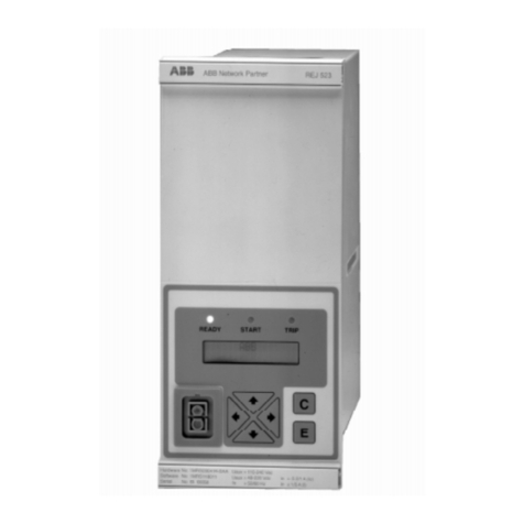
ABB REL 301 User manual


i
I.L. 40-386.3
It is recommended that the user of REL 301/302 equipment become acquainted with the information in this in-
struction leaflet before energizing the system. Failure to do so may result in injury to personnel or damage to
theequipment,andmayaffecttheequipmentwarranty.IftheREL301/302relaysystemismountedinacabinet,
the cabinet must be bolted to the floor, or otherwise secured before REL 301/302 installation, to prevent the
system from tipping over.
All integrated circuits used on the modules are sensitive to and can be damaged by the discharge of static elec-
tricity. Electrostatic discharge precautions should be observed when handling modules or individual
components.
ABB does not assume liability arising out of the application or use of any product or circuit described herein.
ABB reserves the right to make changes to any products herein to improve reliability, function or design. Spec-
ifications and information herein are subject to change without notice. All possible contingencies which may
arise during installation, operation, or maintenance, and all details and variations of this equipment do not pur-
port to be covered by these instructions. If further information is desired by purchaser regarding a particular in-
stallation, operation or maintenance of equipment, the local ABB representative should be contacted.
Copyright ©ASEA BROWN BOVERI, ABB Power T&D Company Inc. 1994
This document contains information that is protected by copyright. All rights are reserved. Reproduction, adap-
tation, or translation without prior written permission is prohibited, except as allowed under the copyright laws.
ABB does not convey any license under its patent rights nor the rights of others.
Trademarks
All terms mentioned in this book that are known to be trademarks or service marks are listed below.
In addition, terms suspected of being trademarks or service marks have been appropriately capitalized.
ABB Power T&D Company Inc. cannot attest to the accuracy of this information. Use of a term in this
book should not be regarded as affecting the validity of any trademark or service mark.
IBM and PC are registered trademarks of the International Business Machines Corporation
WRELCOM is the registered trademark of the ABB Power T&D Company Inc.
INCOM is the registered trademark of the Westinghouse Electric Corporation
!CAUTION

ii
I.L. 40-386.3
PREFACE
Scope
This manual describes the functions and features of the REL 301(Non-pilot Relay System) and REL
302 (Pilot Relay System). It is intended primarily for use by engineers and technicians involved in the
installation, testing, operation and maintenance of the REL 301/302 system.
Equipment Identification
The REL 301/302 equipment is identified by the Catalog Number on the REL 301/302 chassis name-
plate. The Catalog Number can be decoded by using Catalog Number Table in Section 1.6.6.Both REL
301 and REL 302 can be either vertically or horizontally mounted.
Production Changes
When engineering and production changes are made to the REL 301/302 equipment, a revision no-
tation (SUB #) is reflected on the appropriate schematic diagram, and associated parts information.
Equipment Repair
Repair work is done most satisfactorily at the factory. When returning equipment, contact your field
sales representative for RMR authorization. All equipment should be returned in the original packing
containers if possible. Any damage due to improperly packed items will be charged to the customer.
Document Overview
SECTION 1 provides the Product Description. SECTION 2 presents the Functional Specification.
SECTION 3 presents the Setting Calculations. Installation and Operation are described in SECTION
4. Finally, SECTION 5 covers Acceptance Test, Maintenance Test and Calibration procedures.
Contents of Relay System
The REL 301/302 Relay System includes the style numbers, listed below, for each module.
Module Style Number
FT-10 Surge Protection 1502B35
Backplane Surge Protection 1612C53
Option (Reclosing/synch-check) 1614C19
Filter (Input Module) 1612C34
Microprocessor 1613C55
Display (Optional) 1613C69
Power Supply/Relay Outputs 1612C68
VT 1612C80
CT 1612C79
RS232C Communications (Optional) 1614C94

iii
I.L. 40-386.3
TABLE OF CONTENTS
PAGE
SECTION 1PRODUCT DESCRIPTION
1.1 INTRODUCTION..............................................1-1
1.2 REL 301/302 FEATURES......................................1-2
1.3 REL 301/302 CONSTRUCTION...................................1-3
1.4 UNIQUE FEATURES...........................................1-4
1.5 UNIQUE REMOTE COMMUNICATION (WRELCOM®) PROGRAM .............1-6
1.6 SPECIFICATIONS .............................................1-7
SECTION 2FUNCTIONAL DESCRIPTION
2.1 INTRODUCTION..............................................2-1
2.2 LINE MEASUREMENT TECHNIQUES ................................2-1
2.3 MEASUREMENTS ZONES .......................................2-3
2.4 NON-PILOT OPERATION ........................................2-6
2.5 REL 302 PILOT SYSTEM ......................................2-13
2.6 PROGRAMMABLE CONTACT OUTPUTS..............................2-22
2.7 FAULT DATA ..............................................2-22
SECTION 3SETTINGS CALCULATIONS
3.1 MEASUREMENT UNITS AND SETTING RANGES .........................3-1
DISTANCE MEASUREMENTS
OVERCURRENT MEASUREMENTS
UNDERVOLTAGE MEASUREMENTS
3.2 CALCULATION OF REL 301/302 SETTINGS ..........................3-2
3.3 REQUIRED SETTINGS APPLICATIONS ...............................3-7
3.4 RECLOSE INITIATION MODE PROGRAMMING .........................3-12
SECTION 4INSTALLATION AND OPERATION
4.1 SEPARATING THE INNER AND OUTER CHASSIS ........................4-1
4.2 TEST PLUGS AND FTSWITCHES ..................................4-1
4.3 EXTERNAL WIRING ...........................................4-1
4.4 FRONT PANEL MAN-MACHINE INTERFACE ............................4-3
4.5 JUMPER CONTROLS ..........................................4-7
4.6 COMMUNICATION PORT(S)USE ...................................4-8
4.7 FRONT RS-232C COMMUNICATIONS PORT ...........................4-9
4.8 SIXTEEN FAULTS/TARGET DATA .................................4-10
4.9 OSCILLOGRAPHIC DATA .......................................4-10
4.10 PROGRAMMABLE CONTACT OUTPUTS..............................4-11
SECTION 5 REL 301/302 ACCEPTANCE TEST AND MAINTENANCE PROCEDURES
5.1 NON-PILOT ACCEPTANCE TESTS FOR REL 301/302....................5-3
5.2 PILOT ACCEPTANCE TESTS (FOR REL 302 ONLY).....................5-12
5.3 MAINTENANCE PROCEDURES ...................................5-14
5.4 CALIBRATION ..............................................5-15

iv
I.L. 40-386.3
LIST OF FIGURES
PAGE
SECTION 1REL 301/302 RELAY ASSEMBLY IN FT-42 CASE (PHOTO)....................1-1
REL 301/302 LAYOUT (VERTICAL)(SHEET 1OF 2) .......................1-10
REL 301/302 LAYOUT (HORIZONTAL)(SHEET 2OF 2......................1-11
REL 301/302 OUTER CHASSIS (PHOTO)...............................1-12
REL 301/302 INNER CHASSIS (PHOTO)...............................1-13
REL 301/302 RELAY PROGRAM FUNCTIONS ............................1-14
SECTION 2REL 301/302 CHARACTERISTICS /R-X DIAGRAM ........................2-23
MHO CHARACTERISTIC FOR PHASE-GROUND FAULTS.......................2-24
MHO CHARACTERISTICS FOR THREE-PHASE FAULTS
(NOLOAD FLOW)..............................................2-25
MHO CHARACTERISTICS FOR PHASE-TO-PHASE AND
TWO PHASE-TO-GROUND FAULTS (NOLOAD FLOW)........................2-25
LOGIC DRAWING SYMBOLS ........................................2-26
REL 301/302 ZONE-1TRIP LOGIC..................................2-27
REL 301/302 ZONE-2TRIP LOGIC..................................2-27
REL 301/302 ZONE-3TRIP LOGIC..................................2-28
REL 301/302 ZONE-1EXTENSION SCHEME ...........................2-28
INVERSE TIME OVERCURRENT GROUND BACKUP LOGIC .....................2-29
LOSS-OF-POTENTIAL LOGIC ........................................2-29
LOSS-OF-POTENTIAL LOGIC (SYSTEM DIAGRAM)..........................2-30
LOSS OF CURRENT MONITORING LOGIC ................................2-30
OVERCURRENT SUPERVISION .......................................2-31
INSTANTANEOUS OVERCURRENT HIGHSET TRIP LOGIC ......................2-31
REL 301/302 CLOSE-INTO-FAULT TRIP (CIFT) LOGIC ....................2-32
REL 301/302 UNEQUAL-POLE-CLOSING LOAD PICKUP TRIP LOGIC ............2-32
LOAD LOSS ACCELERATED TRIP LOGIC ................................2-33
OUT-OF-STEP BLOCK LOGIC .......................................2-33
OUT-OF-STEP BLOCK LOGIC (BLINDER CHARACTERISTICS)...................2-33
RECLOSING INITIATION LOGIC.......................................2-34
POTT/UNBLOCKING PILOT RELAY ...................................2-34
POTT/UNBLOCKING PILOT TRIP LOGIC ................................2-35
CARRIER KEYING/RECEIVING LOGIC IN POTT/UNBLOCKING SCHEMES ..........2-35
PUTT SCHEME ................................................2-36
BLOCKING SYSTEM LOGIC .........................................2-36
PLTG SUPPLEMENTED BY FDOG ....................................2-37
REVERSED POWER ON POTT/UNBLOCKING SCHEMES......................2-37
UNEQUAL POLE CLOSING ON FAULT ..................................2-38
ADDITIONAL LOGIC FOR POTT/UNBLOCKING SCHEMES
ON 3-TERMINAL LINE APPLICATION ..................................2-38
ADDITIONAL LOGIC FOR PUTT SCHEME ON 3-TERMINAL
LINE APPLICATION .............................................2-39
WEAKFEED APPLICATION ..........................................2-39
REVERSIBLE ZONE-3PHASE AND GROUND (REVERSE BLOCK LOGIC)...........2-40
CO-2 CURVE CHARACTERISTICS.....................................2-41
CO-5 CURVE CHARACTERISTICS.....................................2-42
CO-6 CURVE CHARACTERISTICS.....................................2-43
Other manuals for REL 301
2
This manual suits for next models
1
Table of contents
Other ABB Relay manuals