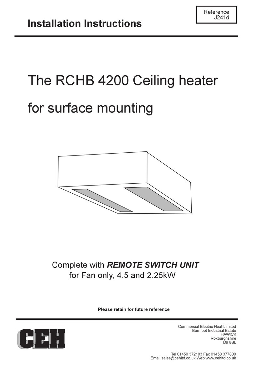
CEH RDH 3000 User manual

Installation Instructions
Reference
J287c
Complete with REMOTE SWITCH UNIT
for Fan only, 3, 2 and 1kW
RDH 3000
Recessed Over Door
Heater
Please retain for future reference
Commercial Electric Heat Limited
Burnfoot Industrial Estate
HAWICK
Roxburghshire
TD9 8SL
Tel 01450 372103 Fax 01450 377800

LOCATION
The heater must be installed at least 2.0m above floor
level. All round minimum clearance dimensions must be
observed.
For optimum effect the heater should be mounted as close
as possible to the top of the doorway. The maximum
recommended mounting height is 2.3m for 3kW and 2.8m
for 4.5, 6.0 and 9.0kW units.
The heater is designed to take input air from the
ceiling void it is therefore imperative that a suitably
sized inlet grille is provided within the ceiling or
enclosure.
The heater must not be covered or the airflow impeded
in any way.
If one inlet grille is at its minimum dimension the other
must have an unrestricted airflow
CONTROL
Remote Switch
Thermostat (CRST16 )
The Remote Switch Unit allows ON/OFF, Fan only with 1,2 or 3 kW.
If a thermostat is required a unit of sufficient current carrying capacity (16A) can be connected in the power
supply to the Remote switch thus switching the heater off when set temperature is reached.
Alternatively it can be connected to
Remove the ìfan switchî to ìheat switchî links and link the supply side of the heat
switches together then connect the thermostat between the fan switch and the heat switches.
control the heating elements only, the fan will run continuously
maintaining air circulation.
CONTENTS
- grille frame and 2 no roundhead woodscrews
Remove from carton and check contents ;
- heater unit
- 2 no support brackets, 4 no. machine screws and 4 no woodscrews
- ODH-RSW three switch control unit
- 25mm cord grip bush and locknut
ELECTRICAL CONNECTION
The heater should be installed in accordance with the latest edition of the IEE Requirements for Electrical
Installation (BS 7671:2001)
The unit should be permanently connected to a suitable 230Vac power supply incorporating a means of
isolation having a contact separation of at least 3mm in all poles.
remote switch unit in suitable location.
Select cabling with 4 cores and earth and of appropriate size for current and volt drop.
Pass cable/s through cord grip in back of unit. Leave sufficient length for connection but ensuring cables do
not foul blower unit. Make off connections to connector block and earth stud in accordance with circuit
diagram RDH-W-001 (copy on back page )
If remote switching is not required connect power supply to L and N and link L,LI and LII with 2.5sqmm
cable.
Tighten up cord grip. Replace cover.
Remove heater cover, position heater in ceiling (See Fixing). Fix
A means of disconnection having a contact separation of 3mm in all poles should be incorporated.
IMPORTANT : always check to ensure the heating elements cannot be energised without the fan
running.
WARNING THE HEATER MUST BE EARTHED
OVER TEMPERATURE CUT OUT
To RESET -
Should the heater exceed normal operating temperature the over temperature cut out on the heating
elements will operate.
switch off power to the unit and allow to cool before switching on again. If the problem persists
consult a suitably qualified person.
min
20
min
100
min
30
SAFETY
The correct procedures for working at height must be adopted when installing this heater.
The heater must be installed by a suitably qualified person in accordance with current regulations.

FIXING
a standard 600mm x 600mm modular ceiling
system.
(see Fig 1). Ensure sufficient space is left to allow the insertion of the grille frame
between heater and bracket. This option may require electrical connection prior to positioning. T
frame
Fitting in plasterboard type ceiling or bulkhead
The unit can be fixed in two ways depending on access available.(Note future access will be required for
servicing)
1) Locate
2) Locate the brackets to sit on top of the support frame (see Fig 2).Position the grille frame in the opening
and loosely fix with the 2 round headed screws provided. Place unit in ceiling from above and position within
grille frame. Secure brackets with woodscrews provided, tighten grille frame fixing screws.
The unit weighs 6kgs and as such can be mounted directly in a correctly installed modular ceiling. As an
added precaution additional ceiling supports can be added adjacent to the heater.
Locate the brackets to sit on top of the T bar frame. The ceiling tile is cut back as appropriate and finished
either with the grille frame or an additional T bar section.
Additional fixings may be required if the ceiling construction is not strong enough to take the heater weight.
Two 8mm holes are provided in the top of the heater to allow the fixing of drop rods (by others).
Fitting in modular ceiling.
Drop rod fixing
This unit is designed for installation in a plasterboard or similar ceiling where a free height above the surface
of the ceiling is at least 230mm. It is also sized to fit within
A 580mm x 130mm hole should be made in the ceiling and suitably framed.
Fix support brackets, with machine screws provided, to screwed inserts in side of unit
the brackets flush with the front of the heater. Place unit in ceiling from below and secure brackets
with woodscrews provided.
he grille
is then positioned and fixed with the 2 round headed screws provided.
The manufacturers reserve the right to change the specification at any time without prior notice EO&E
MAINTENANCE
Isolate the heater and remove any build up of dust etc. every 6 months. Check that the heater has not been
covered or the airflow restricted in any way.
Fig 1 Fig 2
WARRANTY
This product is guaranteed, in accordance with our Conditions of Sale, for a period of 12 months from date of
purchase. We will repair or replace, at our discretion, any part found to be defective. We cannot accept
responsibility for any consequential liability.
The warranty will be invalid if the heater has not been installed in accordance with these instructions.
This does not affect your statutory rights.

Commercial Electric Heat Limited
HAWICK TD9 8SL
No Part No Description
No DateRevision
Title
RevDrawing No.
Date
Drawn by
Scale
L011
RDH-W-001 1nts
NEB 06.09.00
RDH 3000
Recessed Over Door
Heater
3Connector
Block
1Heating
Element
4Blower
Unit
6Over temp
cut out
2Fan
Motor
5
Schematic diagram
1
2
3
B081-01
D002-01
F003
Heating element
Fan motor
Connector block
4 C002 Blower unit
2kW
1kW
L
LI
L
LII
2kW1kW
N
N
5ODH-RSW Remote Switch Unit
Add external cut outs 11/04
6O T cut out
IMPORTANT:
Any modification to the switching in
this circuit must ensure that the
heating elements cannot be energised
without the fan running.
Remote Switch ODH-RSW
1
Heating element incorporates over temperature cut out.
To reset:
Switch off and allow to cool (5 minutes) then restore supply
Heater does not function again until power has been removed
from cut out.
L LI LII
3kW
1
L
N
2
P01
Table of contents
Other CEH Heater manuals
Popular Heater manuals by other brands

Harvia
Harvia K10G-U1 owner's manual

FRENGER systems
FRENGER systems EIR3000 Mounting and installation

Vents
Vents AOE Series user manual

SAMUEL JACKSON
SAMUEL JACKSON Vulcain Service manual

OC IMP Klima
OC IMP Klima TKV Series Installation and start-up manual

Zehnder Rittling
Zehnder Rittling Zenia operating instructions