- 7 -
1. Location
•Place the unit in a properly ventilated location. If it is not, heat exhausted
by the condensing unit will build up and the cooling system will not operate
properly.
•Cooling unit shall be elevated to avoid possible flooding and shaded from
direct sun. It shall not be exposed to temperatures higher than 110 °F or
lower than 50 °F (optional low ambient kit available).
•Leave minimum 5 feet clearance for hot air exhaust and leave minimum 1
foot clearance for the fresh air intake.
•There is a gravity drain line and the unit shall be installed level or with a
slight angle toward the drain connection.
•Supply air flow shall be unobstructed for at least 12” for free installation or
2” for deflector installation and return air shall be unobstructed for 6”.
•Overall combined supply + return or exhaust + intake duct length can be
up to 50 ft long.
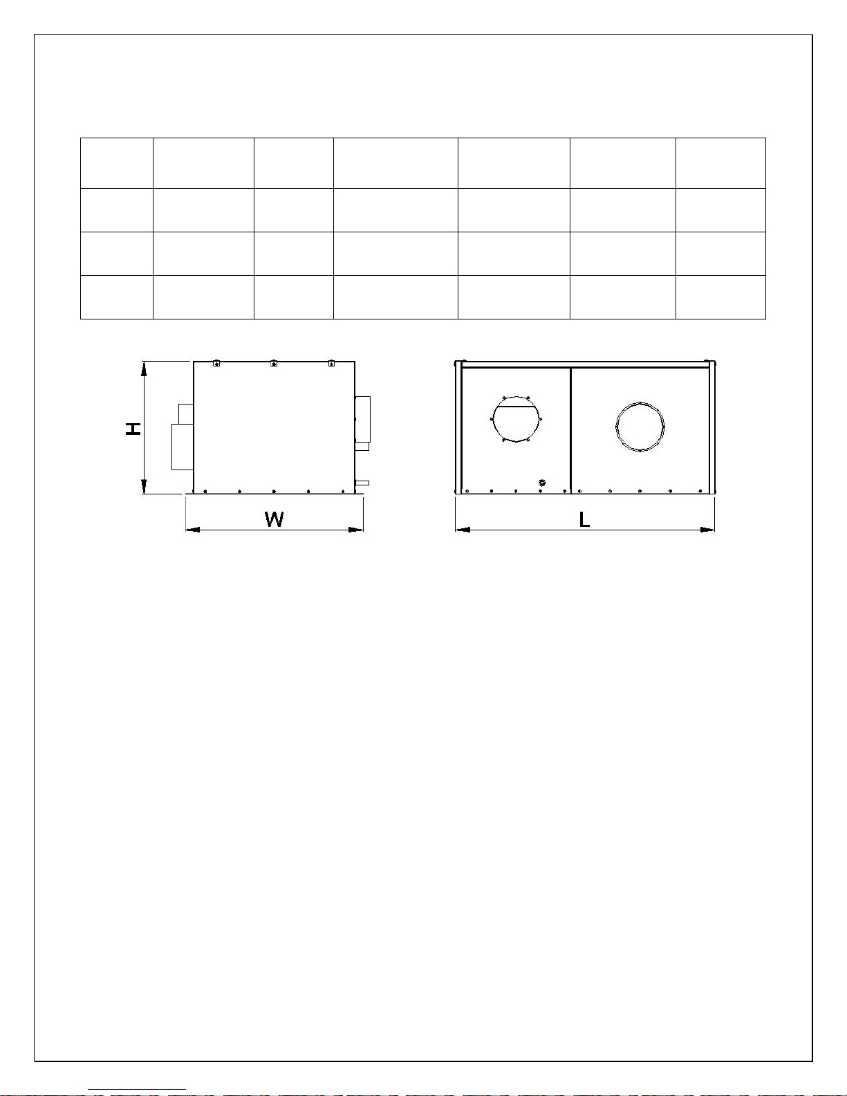
2. Mounting
•The unit must be mounted on a floor or slab that is level and strong
enough to support up to 300lb.
•There are six ½” bolts required to secure the unit base.
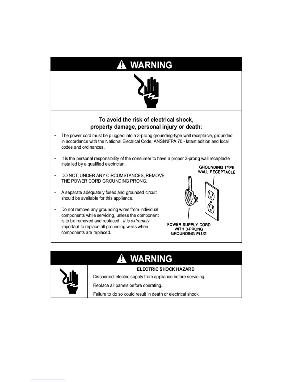
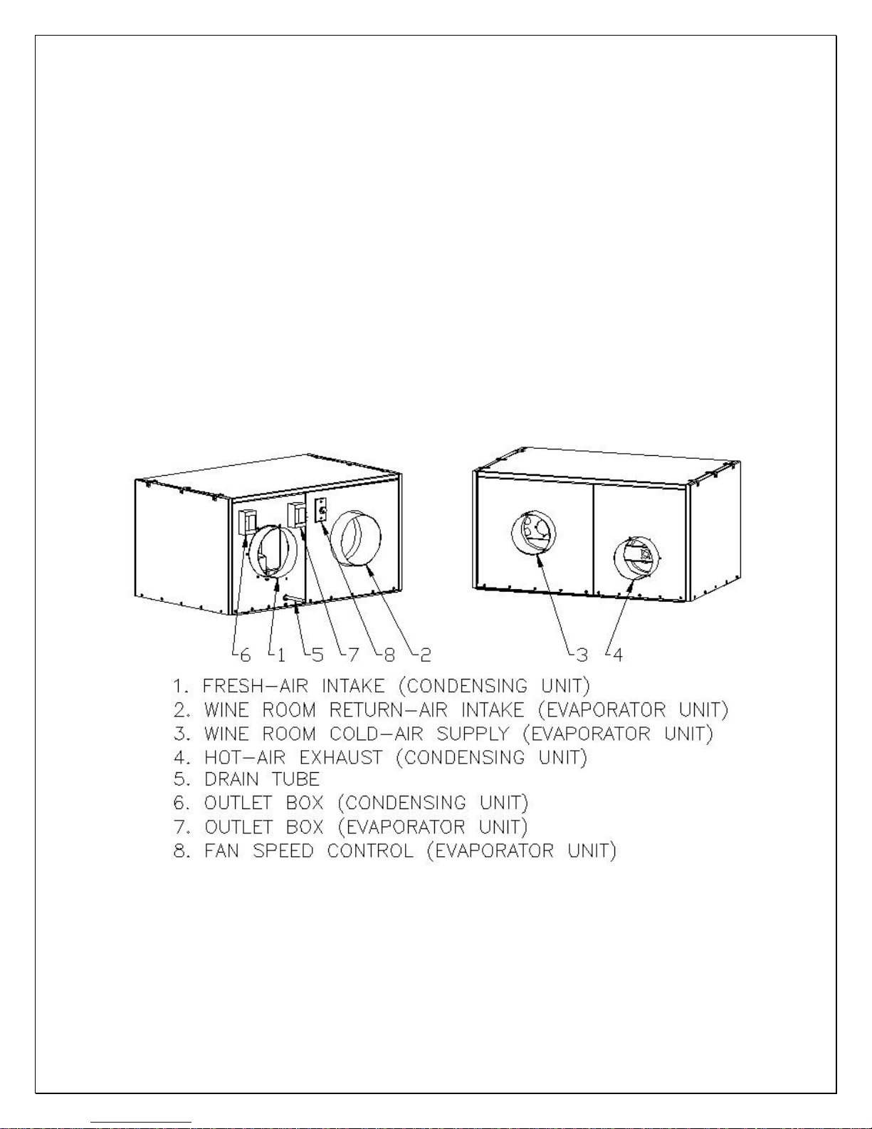
3. Customer Wiring
•Use 14 AWG wires.
•If it is CellarTec 1/3 Ton-DS without low ambient kit, go to the next step.
Connect wires in the outlet box of the condensing unit to the power lines
•Connect wires in the outlet box of the evaporator unit to the temperature
controller and then connect the controller to the power lines.
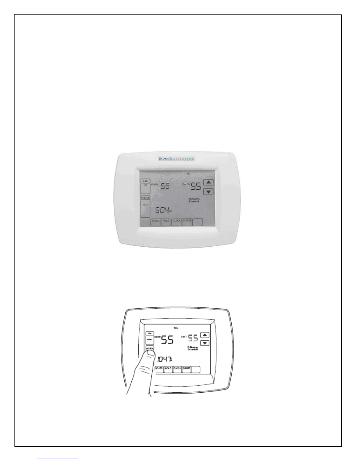
4. Thermostat and Air Sensor(USE 18 GAUGE THERMOSTAT WIRE)
•The thermostat with a built-in air sensor can be installed in the wine room
5 ft above the floor in an area with good air circulation at average temp.
•If the thermostat is mounted outside the wine room, a remote air sensor is
required inside the wine room. The air sensor can be located in a well
circulated or in the return air area, but not the supply air or air dead area.
•If air sensor is in a return duct, the evaporator fans shall be running all the
time. Due to the temperature differential the temperature setting needs to
be adjusted in order to maintain the proper wine room temperature.
5. Air Flow (Evaporator unit)
•If the overall duct length is less than 50ft, it is necessary to check the air
flow to meet the specified CFM. It may use fan speed control to adjust the
system refrigeration performance to achieve 8-10°F differential between
return air and supply air while wine room temperature is maintained 55°F.
Turn the control knob clockwise to decrease the air flow or counter-
clockwise to increase the air flow.