Cemline Corporation CEM-TROL User manual

$5.00
P. O. Box 55, Cheswick, PA, 15024
Phone: (724) 274-5430 •FAX (724) 274-5448
www.cemline.com
Installation, Operation, and Maintenance Manual
CEMLINE CORPORATION®
CEM-TROL Solid State Control Module
and Electronic Control Valves

i
Table of Contents
Section Page
Disclaimers ..................................................................................................................... 1
Contact Information........................................................................................................ 1
General Notes and Warnings .......................................................................................... 2
Notes ................................................................................................................... 2
Warnings............................................................................................................. 2
Connection Electrical Power Source .................................................................. 3
The Controller Overview ................................................................................................ 4
Contractor Wiring ........................................................................................................... 7
Ratings ............................................................................................................................ 7
Control Screens............................................................................................................... 8
Setting the Controller...................................................................................................... 9
Home Screen....................................................................................................... 10
Alternative Home Screen.................................................................................... 11
Set Point Degree F .............................................................................................. 11
Primary High Limit Temperature ....................................................................... 12
Primary High Limit Temperature Reset Differential.......................................... 13
Secondary High Limit Temperature ................................................................... 14
Secondary High Limit Temperature Reset Differential...................................... 14
Control Valves .................................................................................................... 15
PID Gain Kp (Proportional)................................................................................ 16
PID Gain Ki (Integral) ........................................................................................ 16
PID Gain Kd (Derivative)................................................................................... 17
Remote Control .................................................................................................. 17
Control Output ................................................................................................... 18
Maximum Output ............................................................................................... 20
Initial Settings ..................................................................................................... 20
Diagnostics.......................................................................................................... 20

LL
About................................................................................................................... 21
Quit...................................................................................................................... 21
Terminal Board Layout ................................................................................................... 22
Building Automation Control Interface .......................................................................... 23
Remote On-Off ................................................................................................... 23
Remote Temperature Read Out........................................................................... 24
Remote Temperature Set Point ........................................................................... 24
Testing the Temperature Sensor ..................................................................................... 25
Wiring Diagram for Self-Contained Temperature Pilot Operated Control Valves ........ 26
Wiring Diagram for Pneumatically Operated Control Valves........................................ 27
Wiring Diagram for Warren Controls with AmurAct Actuator...................................... 28
Wiring Diagram for MXG and MFX Valves.................................................................. 29
Wiring Diagram for M2H and M3P Valves ................................................................... 30
Wiring Diagram for MVF Valves................................................................................... 31
MXG and MXF Valve Information ............................................................................... 32
M3P and M2H Valve Information.................................................................................. 34
MVF Valve Information................................................................................................. 35
General Valve Information............................................................................................. 37
Magnetic Coil Resistance Information........................................................................... 38
Warren ControlsAmurAct Actuator Valve Information................................................ 39
2011 Cemline Corporation. All Rights Reserved.
All trademarks in this manual are property of Cemline Corporation, unless otherwise noted or in
any other way set forth as a third party rights. Unauthorized use of these trademarks, as well as the
materials presented in this manual, is expressly prohibited and constitutes a violation of the
intellectual property rights of Cemline Corporation.

1
Disclaimers
This Installation, Operation, and Maintenance Manual is intended to be as complete and up to date
as possible. It covers the installation, operation, and maintenance procedures for CEMLINE
CORPORATION’s CEM-TROL control module and electronic control valves. CEMLINE®
reserves the right to update this manual and other product information concerning installation,
operation, and/or maintenance, at any time and without obligation to notify product owners of such
changes.
CEMLINE is not responsible for inaccuracies in specifications, procedures and/or the content of
other product literature, supplied by the manufacturers of components used in CEMLINE CEM-
TROL control module. CEMLINE strives to use only the highest quality components; however,
CEMLINE has no direct control over their manufacture, or their consistent quality.
CEMLINE is not responsible for injury to personnel or product damage due to the improper
installation, operation, and/or maintenance of CEMLINE Electronic Controls. All installation,
operation, and maintenance procedures should only be performed by trained/certified personnel. All
personnel performing these procedures should completely and carefully read and understand all
supplied materials before attempting the procedures. All personnel should pay strict attention to all
Notes, Cautions, and Warnings that appear within the procedures detailed in this manual.
CEMLINE welcomes user input as to suggestions for product or manual improvement.
Contact Information
For information concerning warranties, or for questions pertaining to the installation,
operation or maintenance of CEMLINE products, contact:
CEMLINE CORPORATION
P.O. Box 55
Cheswick, PA 15024
USA Phone: (724) 274-5430
USA Fax: (724) 274-5448
www.cemline.com
To order replacement parts, contact CEMLINE CORPORATION at the address listed above, or call
toll free:
USA/Canada/Caribbean Phone: (800) 245-6268
Note: Please include the model and serial number of the unit for which the parts are being
ordered. If ordering by phone, please have this information readily available.

2
General Notes and Warnings
Notes
This manual is intended to cover installation, operation, and maintenance procedures for
CEMLINE CORPORATION CEM-TROL control module and electronic control valves.
If questions are not answered by this manual, or if specific installation, operation, and/or -
maintenance procedures are not clearly understood, contact CEMLINE CORPORATION for
clarification before proceeding.
All installation, operation, and maintenance procedures should be performed only by
experienced, trained and certified personnel. Personnel should be trained in and familiar with
correct piping and electrical procedures and methods, and should be experienced in working
with hot/boiler water systems and steam systems.
CEMLINE CORPORATION CEM-TROL control module and other electronic controls are
designed for indoor use only, unless otherwise required by design specifications.
If the unit is damaged during installation, operation, or maintenance, complete the following
steps:
1. Turn off and lock out the electric power supply to the unit in an approved manner.
2. Turn off all incoming steam/hot water valves.
3. Contact in-house maintenance personnel or CEMLINE CORPORATION for
instructions.
Warnings !
As with any piece of equipment that utilizes hot/boiler water or steam and electricity, the potential
exists for severe personal injury if proper installation, operation, and maintenance procedures are
not followed. Listed on the following pages are specific warnings pertaining to CEMLINE
Electronic Controls. All warnings should be carefully read and understood. All precautions
contained in the warnings should be carefully followed to reduce the chance of injury.
Note: Throughout this manual, warnings will be denoted by the symbol .
All documentation for each major component has been included with the unit. It is strongly
recommended that each document be reviewed before attempting any installation, operation, or
maintenance procedures.
The documentation for each major component may also contain warnings and cautions identified by
the manufacturer of each component. These warnings and cautions may be specific for the
particular component, and therefore not covered in this general Installation, Operation, and
Maintenance Manual. They should also be carefully reviewed before attempting installation,
operation, or maintenance procedures.

3
The combination of electricity and water can pose a very dangerous situation. Assure that all
power has been shut off/disconnected and locked out in an appropriate manner, before
attempting any installation or maintenance procedures.
Areas of potential danger:
1. all electric power leads and connections;
2. all hot/boiler water lines, steam lines, joints, valves, and relief valves; and
3. all joints at valve, gauges, etc.
Before attempting any installation, operation, or maintenance procedures pertaining to the unit.
1. Assure that the electric power supply has been turned off and locked out in an approved
manner;
Hot/boiler water and steam present a situation that can be very dangerous due to the fact it
is under pressure and at very high temperatures. To avoid possible injury or death, use
common sense and follow all accepted and recommended procedures when performing
installation, operation, and maintenance procedures.
Connecting the Electric Power Source
All installation procedures involving electric power connection should only be performed by
trained, certified electricians.
Hot/boiler water and steam present a situation that can be very dangerous because of the high
temperatures and pressures. Use common sense and follow all accepted and recommended
procedures when performing installation, operation, and maintenance procedures to avoid
possible injury or death.
The combination of electricity and water can pose a very dangerous situation. Assure that all
power has been shut off/disconnected and locked out in an approved manner, before
attempting any installation or maintenance procedures.
The CEMLINE Packaged Water Heaters have been wired during assembly. Connecting the electric
power supply to the unit consists of connecting the correct voltage, phase, and amperage power
leads to the terminal strip or circuit breaker. The exact voltage, phase, and amperage requirements
for the unit can be determined from the rating plate affixed to the jacket of the unit, or from the
Submittal Sheet and Wiring Diagrams supplied with the unit.

4
The Controller - Overview
Cemline CEM-TROL control module is a solid state controller designed to control temperatures and
limit(s) on Cemline Packaged Water Heaters.
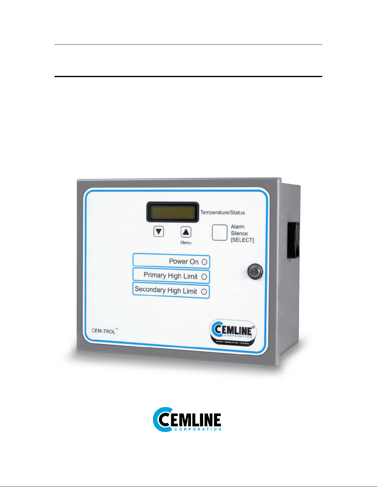
The CEM-TROL is supplied with a LED backlit LCD display. LED pilot lights are supplied to
indicate On-Off, primary high limit temperature, and secondary high limit temperature. The CEM-
TROL control module allows the owner to set the operating temperature, primary high temperature
limit and the secondary temperature high limit on the display screen. The CEM-TROL control
module has over temperature alarm lights and an alarm horn with built in alarm silence relay. The
CEM-TROL control module is supplied with dry contact closure outputs to indicate to building
automation system (BAS): power on, primary high temperature, secondary high temperature, and
any alarm. The CEM-TROL control module allows the BAS to turn the Cemline Packaged Water
Heater on or off through a remote relay suitable for 24 VAc, 1 amp. The control module allows the
BAS to remotely monitor the operating temperature and remotely set the operating temperature.
The control module is supplied with an on-off switch and is mounted in a NEMA 4 enclosure.
Built in remote start stop: This feature allows the Packaged Water Heater to be started or stopped
from a remote location. Typically this would be accomplished from the Building Automation
System (BAS) . Requires a dry contact suitable for 24 VAc and 1 amp. Terminal block P1
terminals 1 – 2 on the panel is where the BAS on-off is wired.
Built in On-Off Switch: Allows for local on-off and is convenient for service in the unlikely event
service is required. This switch is mounted in the side of the panel.
Built in Alarm Horn: The alarm horn will sound and LED will light red on primary high
temperature limit and/or secondary high temperature limit. If either high temperature limits are
exceeded the alarm horn will also sound and the alarm light(s) will light red. The CEM-TROL also
features an alarm silence relay which will silence the alarm but not the fault light when the
generator is being serviced. When the fault is cleared both the alarm and fault light(s) will
automatically reset.
Built in PID controller: The PID control in the CEM-TROL allows the user to easily select the
operating temperature set point of the water heater. The controller reads the temperature of the
heated water from a temperature sensor in the water heater. Based upon the water temperature, the
controller then sends a 0 –10 VDC output signal to the control valve to open or close the valve
accordingly. In order to use this functionality of the CEM-TROL must be wired to either a
pneumatic control valve with an I-P transducer or an electronic control valve. This feature is not
functional when using a pilot operated valve with a self-contained temperature pilot.
The CEM-TROL is designed with the P-I-D control logic.
P is proportional. The proportional is used to handle the present. Proportional is a constant used to
send a signal to the output. Proportional control with a set point of 140 oF and a proportional band
of 10 would have a 100% (10 VDC) output at 130 deg F, 50% (5 VDC) output at 135 oF and 10%
(1 VDC) output at 139 deg F oF.

5
I is integral. The integral measures error over a short period of time to develop a constant used to
send a signal to the output. The integral is then added to the proportional to eliminate error.
D is derivative. The derivative is often referred to as rate. Derivative is used to respond to a
change in the system. The larger the derivative the more rapidly the controller can respond to
changes within the system.
Built in operating temperature readouts: The CEM-TROL features an easy to read LED digital
readout of the water temperature in the water heater.
Built in primary high temperature cut off and alarm: In the event of high temperature, the CEM-
TROL will close the source steam, boiler water, or HTHW supply valve and sound an alarm.
Built in secondary high temperature limit and alarm: In the event of secondary high temperature set
point is exceeded the CEM-TROL will open an optionally supplied domestic water solenoid valve
to relieve the vessel of overheated water and sound an alarm.
Built in remote temperature set point: The BAS can remotely set the operating temperature of the
water heater. This requires the use of a pneumatic control valve with an I-P transducer or an
electronic control valve. This feature is not functional when using a pilot operated valve with a
self-contained temperature pilot.
Built in LED/LCD display of functions and alarms: The CEM-TROL is designed for the user to tell
at a glance how the system is operating. The built in LED displays make troubleshooting simple.
Function LED Indicator 1 LED Indicator 2
Power ON Green = Power On Blank = No power
Primary High Limit Blank = Temperature below
primary high limit set point.
Red = Primary high limit set
point has been exceeded.
Secondary High Limit Blank = Temperature below
secondary high limit set point.
Red = Secondary high limit set
point has been exceeded.
CEM-TROL units version 2.0 and higher will display the below alarm status on the LCD screen if
the temperature sensor(s) are not attached or are defective. In order to determine the version of the
CEM-TROL please refer to the ‘About’ section on page 21 of this manual
LCD Display Description
Sensor Loss 1 The primary sensor wired to terminal block P2 - terminals 1 & 2 is not
connected and needs to be connected or the sensor is faulty or defective
and needs to be replaced.
Sensor Loss 2 The secondary sensor wired to terminal block P2 - terminals 3 & 4 is not
connected and needs to be connected or the sensor is faulty or defective
and needs to be replaced.
Sensor Loss 3 Both the primary sensor wired to terminal block P2 - terminals 1 & 2 and
the secondary sensor wired to terminal block P2 - terminals 3 & 4 are not
connected and need to be connected or the sensors are faulty or defective
and need to be replaced.

6
Built in contacts to notify BAS (Building Automation System) of functions and alarms: This
control allows for simple and reliable interface from a remote location. The BAS can also start and
stop the packaged water heater. BAS can remotely read the temperature in the packaged water
heater via a 4 – 20 mA signal whereby 4 mA= 32 oF and 20 mA = 212oF. BAS can remotely set
the temperature of the packaged water heater between 50 and 160 oF using a 4 – 20 mA signal
whereby 4 mA= 32 oF and 20 mA = 212 oF.
Power ON
Primary High Limit
Secondary High Limit
Alarm
Operating temperature (via a 4-20 mA signal)
(4 mA = 32 oF: 20 mA = 212 oF)

7
Contractor Wiring
All Power Connections should be performed by a trained , certified electrician. Be sure the
factory supplied on-off switch is in the OFF position before connecting to building power.
Field wiring: Installer must run feed wires to terminals on panel mounted on-off disconnect switch
and green ground wire to ground lug. Units are normally wired for 120 volt single phase input.
Warning: Before drilling hole in panel for conduit connection of power carefully open door
and verify that nothing in panel will be interfered with. BE CAREFUL not to get any drill
shavings or metal slug on board or transformer or disconnect switch.
Panel is normally factory shipped for 120
Volt/ 1 phase/60/50 Hz. If so desired
220/1/50 or 60 Hz power can be used. To
convert to 220 volt input it is necessary to
reconfigure the 24 volt output transformer.
Below is the wiring diagram for 120 volt
and 220 volt input.
CAUTION: Before attempting to rewire the transformer be sure power coming to the
unit is turned off and locked out in an approved manor.
Ratings
Input: selectable 120/220 VAC –50/60 Hz @120 Vac min 90 volt max 130 volt
Output Contacts: 1 amp at 24 Vac
Building Automation outputs: Dry contacts, NO .5 amp maximum, non inductive
Display: LED display with resolution of
.3 % of scale
Available temperature set range:
50 – 160 oF
Operating ambient temperature:
Min 32 Deg F max 140 deg F
Operating Humidity:
5% to 95% relative humidity (RH)
non condensing
Alarm approximately 103 db.
NEMA 4 enclosure
The Cemline CEM-TROL is a self contained board and can not be field repaired. For a replacement
board contact Cemline Corporation at the address shown on page one of this manual.

8
Controller Screens
Controller screens:
There are three tactile keys on the front of the panel. The center key, labeled Menu (f), is pushed
to select the desired function. The right key, labeled Alarm Silence [SELECT], is pushed to access
the desired screen. Both the function and setting are read on the LED backlit LCD display.
Pushing the center (Menu f) key will display, in sequence, the following screens :
Screen 1 (Home) Screen 2
Screen 3 Screen 4
Screen 5 Screen 6
Screen7 Screen8
Screen 9 Screen 10
Screen 11 Screen 12
f
Menu
g
Alarm
Silence
[SELECT]
SET: XXX [MODE]
TEMP: XXX Setpoint Deg F.
High Limit 1 Differential 1
High Limit 2 Differential 2
Control Valves PID Gain Kp
PID Gain KdPID Gain Ki
Control OutputRemote Control

9
Screen 13 Screen 14
Screen 15 Screen 16
Screen 17
After 60 seconds in any screen ”Home” screen will be displayed.
Setting the Controller
There are three tactile keys on the front of the panel. The center key, labeled Menuf, is pushed to
select the desired function. The right key, labeled Alarm Silence [SELECT], is pushed to access
the desired screen. Both the function and setting are read on the LED backlit LCD display. The
sequence to access and change any screen is as follows:
1. Press “[Menu f]” (center key) key until desired function appears on the screen.
2. Press “Alarm Silence / [SELECT]” (right key) and a setting will appear on the second
line of the screen.
3. Press “f” key to change setting in an increasing or forward direction or press “g” key
to change the setting in a decreasing or reverse direction. Continue pressing either the “f”
or “g” keys, which will scroll though available settings until desired setting is on the
screen.
4. Press “[SELECT]” key which will store last screen setting into memory and return to
controller screen to “HOME”
Maximum Output Initial Settings
AboutDiagnostics
Quit

10
Instructions for setting each screen:
Home Screen
Below is the screen displayed during normal operation for Cem-trol version 1.0 to 2.9:
Screen 1
Home
MODE will display either show a voltage output or ALARM. The mode will read a voltage output
in normal operation and alarm if any alarm condition occurs. If an alarm condition is cleared the
mode will switch back to normal reading. The voltage output displayed shows the number of volts
the controller is sending to the control valve. The volts displayed will be between 0 – 10, where at
0 volts the control valve will be closed and at 10 volts the control valve will be full open.
SET: This is the operating temperature set point of the water heater.
TEMP: This is the temperature reading of the water in the heater.
CEM-TROL Version 3.2 and higher the display screen will be slightly different than above and is
shown below:
Screen 1 Screen 1
Home - Normal Operation Home – ALARM Mode
Screen 1
Home – Two Control Valves
SET: This is the operating temperature set point of the water heater.
TEMP: This is the temperature reading of the water in the heater.
V1: This is the control voltage output to Control Valve 1.
V2: This is the control voltage output to Control Valve 2. If two valve configuration is selected, see
the “Control Valves” section on page 15 of this manual for more information.
NOTE: The display of V1 and V2 is only available on CEM-TROL’s version 3.2 and
higher. See page 21 and the “About” section to determine the version of the CEM-
TROL.
SET: XXX [MODE]
TEMP: XXX
SET: XXX V1:XX
TEMP: XXX
SET: XXX [ALARM]
TEMP: XXX
SET: XXX V1:XX
TEMP: XXX V2: XX

11
Alternative Home Screen
This screen can be displayed during operation displaying the temperature of both temperature
sensors being used to operate the controller.
The primary temperature sensor, displayed as PRM, temperatures may fluctuate
faster and/or at wider range than the TEMP temperature due to the location of the
sensor within the tank. Cemline allows for the screen to be viewed as the primary
sensor is controlling the number of volts being displayed on the screen and being sent
to the control valve.
When using the self-contained temperature pilot the PRM temperature sensor is not
required because the operating temperature of the water heater will be set by the self-
contained temperature pilot and not the CEM-TROL. Therefore, the PRM will
display a temperature of 212 oF, which will not affect the operation of the unit.
This screen can be displayed by :
To view the alternative home screen:
1. Press and hold the [g] key for 5 seconds and the following screen will appear.
2. This screen will return to the Home Screen after 60 seconds
Alternative Home Screen 1
MODE will display either show a voltage output or ALARM. The mode will read a voltage output
in normal operation and alarm if any alarm condition occurs. If an alarm condition is cleared the
mode will switch back to normal reading. The voltage output displayed shows the number of volts
the controller is sending to the control valve. The volts displayed will be between 0 – 10, where at
0 volts the control valve will be closed and at 10 volts the control valve will be full open.
SET: This is the operating temperature set point of the water heater.
TEMP: This is the secondary temperature sensor temperature reading.
PRM: This is the primary temperature sensor temperature reading.
Set Point Degree F.
This is the operating temperature set point of the water heater. If the water heater was supplied with
either a pneumatic control valve with an I-P transducer or an electronic control valve the
temperature set point of the water heater will be selected using the CEM-TROL. This feature is not
functional when using a pilot operated valve with self-contained temperature pilot.
To set the operating temperature set point:
SET: XXX [XXX]
TEMP: XXX PRM: XXX

12
1. Press the [Menu f] key one (1) time and the following screen will appear:
Screen 2
2. Press the [SELECT] key and the screen will read.
Screen 2
3. Press “f” key to change temperature setting in an increasing direction or press “g” key
to change the temperature setting in a decreasing direction until the desired operating
temperature appears on the screen. The set point temperature is adjustable between
50-160 oF in 1 oF increments. The default value of the operating temperature set point
is 140 oF. If the temperature output desired is above 160 oF, please contact the factory
for special instructions.
4. Press [SELECT] key to place setting in memory and to return to home screen.
Primary High Limit Temperature or Cut Out
This is the primary high limit temperature which is typically set 10 to 20 oF higher than the desired
operating temperature. When the primary high limit temperature or cut out temperature is reached
the controller will cause the main control valve to close.
CAUTION: When using a pilot operated control valve with a self-contained
temperature pilot the operating temperature of the water heater will be set by the self-
contained temperature pilot and not the CEM-TROL. See the Cemline Water Heater
I O & M manual and the self-contained temperature pilot I O & M manual for setting
the operating temperature.
CAUTION: When using the self-contained temperature pilot DO NOT set the
operating temperature greater than the primary or secondary high limit settings. This
will cause improper operation of the unit, with the potential for DANGER by causing
alarms and dump valves to go off.
1. Press the [Menu] key two (2) times and the following screen will appear:
Screen 4
2. Press the [SELECT] key and the screen will read:
Setpoint Deg F.
Setpoint Deg F.
Degrees F [xxx]
High Limit 1

13
Screen 4
3. Press “f” key to change temperature setting in an increasing direction or press “g” key
to change the temperature setting in a decreasing direction until the desired high limit
temperature appears on the screen. The range of the primary high limit temperature set
point is between 5 oF greater than the operating temperature set point and 220 oF in 1 oF
increments. The default value of the primary high limit temperature is 150 oF.
4. Press [SELECT] key to place the setting in memory and return to the home screen.
Primary High Limit Temperature Reset Differential
This is the temperature differential from the primary high limit set point at which the primary high
temperature limit will reset. Normally it is set at 5 oF but can be set between 1 to 20 oF in 1 oF
increments.
To set the primary high limit temperature differential:
1. Press the [Menu] key three (3) times and the following screen will appear:
Screen 4
2. Press the [SELECT] key and the screen will read:
Screen 4
3. Press “f” key to change temperature setting in an increasing direction or press “g” key
to change the temperature setting in a decreasing direction until the desired primary high
limit temperature differential appears on the screen. The range is 1-20 oF in 1 oF
increments.
4. Press [SELECT] key to place the setting in memory and return to the home screen.
High Limit 1
Degrees F [xxx]
Differential 1
Differential 1
Reset Deg F [xxx]

14
Secondary High Temperature Limit
This is the secondary high limit temperature is typically set 20-30 oF higher than the desired
operating temperature. When the secondary high limit temperature is reached a solenoid opens to
dump overheated water to drain. Be sure to pipe the outlet from this solenoid to drain.
CAUTION: When using the self-contained temperature pilot DO NOT set the
operating temperature greater than the primary or secondary high limit settings. This
will cause improper operation of the unit, with the potential for DANGER by causing
alarms and dump valves to go off.
4. Press the [Menu] key four (4) times and the following screen will appear:
Screen 5
5. Press the [SELECT] key and the screen will read:
Screen 5
6. Press “f” key to change temperature setting in an increasing direction or press “g” key
to change the temperature setting in a decreasing direction until the desired high limit
temperature appears on the screen. The range of the secondary limit temperature set
point is between 2 oF greater than the primary high limit temperature set point and 230
oF in 1 oF increments. The default value of the primary high limit temperature is 160 oF.
4. Press [SELECT] key to place the setting in memory and return to the home screen.
Secondary High Limit Temperature Reset Differential
This is the temperature differential from the secondary high limit set point at which the secondary
high limit temperature will reset. Normally it is set at 5 oF but can be set from 1 to 20 oF in 1 oF
increments.
To set the secondary high limit temperature differential:
5. Press the [Menu] key five (5) times and the following screen will appear:
Screen 6
High Limit 2
High Limit 2
Degrees F [xxx]
Differential 2

15
6. Press the [SELECT] key and the screen will read:
Screen 6
7. Press “f” key to change temperature setting in an increasing direction or press “g” key
to change the temperature setting in a decreasing direction until the desired secondary
high limit temperature differential appears on the screen. The range is 1-20 oF in 1 oF
increments.
8. Press [SELECT] key to place the setting in memory and return to the home screen.
Control Valves
If desired the control module can be used to control two control valves set up in a 1/3 – 2/3 piping
configuration.
To set the control valve option:
1. Press the [Menu] key six (6) times and the following screen will appear:
Screen 7
2. Press the [SELECT] key and the screen will read:
Screen 7
3. Press “f” key to change control valve setting in an increasing direction or press “g”
key to change the control setting in a decreasing direction until the desired control valve
setting appears on the screen. The control valve choices are “Single Control” when one
control valve is being utilized or “Dual Control” when two control valves are being
utilized.
4. Press [SELECT] key to place setting in memory and return to home screen.
Differential 2
Reset Deg F [xxx]
Control Valves
Control Valves
Single Control

16
Setting PID Gain Kp (Proportional)
The operating controls are factory preset for optimal control of the water heater. The Kp
(Proportional) is used to handle the present. Kp (proportional) is a constant used to send a signal to
the output. The proportional control with a set point of 140 oF and a proportional band of 10 would
have a 100% output at 130 oF, 50% output at 135 oF and 10% output at 139 oF. The default value of
the Kp (proportional) is 8 (oF). The Kp (Proportional) setting of the controller can be determined
and if necessary changed as follows:
1. Press the [Menu] key seven (7) times and the following screen will appear:
Screen 8
2. Press the [SELECT] key and the screen will read:
Screen 8
3. Press “f” key to change the Gain Kp setting in an increasing direction or press “g”
key to change the Gain Kp setting in a decreasing direction until the desired secondary
high limit temperature differential appears on the screen. The range is 5-30 (oF).
4. Press [Menu] key to place the setting in memory and return to the home screen.
Setting PID Gain Ki (Integral)
The operating controls are factory preset for optimal control of the water heater. The Ki (Integral)
measures error over a short period of time to a constant used to send a signal to the output. The
default value of the Ki (integral) is 2. The Ki (integral) setting of the controller can be determined
and if necessary changed as follows:
1. Press the [Menu] key eight (8) times and the following screen will appear:
Screen 9
2. Press the [SELECT] key and the screen will read:
Screen 9
PID Gain Kp
PID Gain Kp
Kp[8]
PID Gain Ki
PID Gain Ki
Ki[2]

17
3. Press “f” key to change Gain Ki setting in an increasing direction or press “g” key to
change the Gain Ki setting in a decreasing direction until the desired secondary high
limit temperature differential appears on the screen. The range is 0-30.
4. Press [SELECT] key to place the setting in memory and return to the home screen.
Setting PID Gain Kd (Derivative)
The operating controls are factory preset for optimal control of the water heater. The Kd
(derivative) measures error over a short period of time to a constant used to send a signal to the
output. The default value of the Kd (derivative) is 10. The Kd (derivative) setting of the controller
can be determined and if necessary changed as follows:
1. Press the [Menu] key nine (9) times and the following screen will appear:
Screen 10
2. Press the [SELECT] key and the screen will read:
Screen 10
3. Press “f” key to change Gain Kd setting in an increasing direction or press “g” key to
change the Gain Kd setting in a decreasing direction until the desired secondary high
limit temperature differential appears on the screen. The range is 0-30.
4. Press [SELECT] key to place the setting in memory and return to the home screen.
Remote Control
The CEM-TROL can operate with a remote temperature set point. The remote temperature set
point allows the Building Automation System (BAS) to supply a constant 4 – 20 mA signal to the
controller.
CAUTION: When using the remote set point DO NOT set the operating
temperature greater than the primary or secondary high limit settings. This will
cause improper operation of the unit, with the potential for DANGER by causing
alarms and dump valves to go off.
CAUTION: Once the Remote Control is Enabled the local setting is no longer used
unless the Remote Control has been Disabled.
PID Gain Kd
PID Gain Kd
Kd[10]
Table of contents
Popular Control Unit manuals by other brands

Singer Valve
Singer Valve 106-2SC-PCO Installation, operating and maintenance instructions

Honeywell
Honeywell NOTIFIER XP6-MA Installation and maintenance instructions

Xylem
Xylem Aquavar SPD SPD20050 instruction manual

Eaton
Eaton Crouse-hinds series Installation & maintenance information

Egcon
Egcon GCU DG4 user manual

YOKOGAWA
YOKOGAWA YFGW410 user manual

Huawei
Huawei RTN 380H Quick installation guide

ECG
ECG AD8232 Assembly manual

Parker
Parker PSSTACM12A Installation & service instructions

RDZ
RDZ WI-SA Technical manual

Viessmann
Viessmann VITOTRONIC 100 Installation and service instructions

Siemens
Siemens ASIsafe SIRIUS 3RK1205-0B.00-0AA2 Original operating instructions