Koganei FVN01-01 Series User manual

Operating vacuum pressure
Recommended tube
-100 kPa [-29.5 inHg]
Nylon tube, urethane tube
Operating temperature range
0〜0.9MPa [0〜131 psi]
Operating pressure range
0〜60℃[32〜140℉]
1 pc.Sales unit
AirMedia
SpecificationsSymbol
Inner Construction, Major Parts and Materials
●Valves for switching the flow path in the pipes.
●Can be installed in various locations, including horizontal
connections.
●
Both 3-way valves (standard type, with exhaust function)
and 2-way valves are available.
2 (A)
2-way valve
1 (P)
-
KCF2611Z
2 (A)
3-way valve
1 (P)
3 (R)
-
Note: The R port of the 3-way valves cannot be connected to pipes.
Elastic sleeve (NBR)
Tube
Release ring (polyacetal)
Lock claw (stainless steel)
Plastic body (polybutylene terephthalate)
Metal body (brass, electroless nickel plated)
Guide ring (brass, electroless nickel plated)
Selector knob (polyacetal)
Spool (brass, electroless nickel plated)
O-ring (NBR)
Vent
aOUT
INa
Functions
The 3-way valve can exhaust residual pressure (residual pressure remained in
mounted equipment) left behind in the outlet port side when air has been shut off.
Ensures safe operations during equipment maintenance and repairs, etc.
The 2-way valve is suitable for air supply to tanks and other equipment where
exhausting residual pressure is not desired.
The 2-way valve is also suitable for use in vacuum piping.
Residual pressure
exhaust
Inlet port
(IN side)
Outlet port
(OUT side)
Close
●3-way valve
②is a bidirectional valve. ③is a tri-directional valve.
Top of cap lever
HAND VALVES
032016

Nipple
●FVN
Thread size R
1/8-1/8
1/4-1/8
1/4-1/4
3/8-1/4
3/8-3/8
2(A)
1(P)
Order codes
FVN
Number of ports
Blank ───3-way valve
2─────2-way valve
Thread size of the outlet port
Thread size of the inlet port
Dimensions mm
Nipple
FVN
2(A)
1(P)
E2
E1 L2
B1 B2
L1
A1
R1
H1
R2
A2
H2
F2
10.5
OUT
IN
2-φ4.2
φPF1
FVN01-01
FVN02-01
Model R1 R2 A1 A2 E1 E2 L1 Note
L2 Note
φP B1 B2
Width
across
flats
H1
Width
across
flats
H2
F1 F2 T
Effective
area
mm2
Mass
g
FVN01-01-□
1/8 1/8 8 8 17 40.5 29.5 29.5 16.5 33.5 33.5 14 14 18 8 ─8.8 43
FVN02-01-□
1/4 1/8 11 8 17 40.5 30.5 29.5 16.5 36.5 33.5 14 14 18 8 ─9 49
FVN02-02-□
1/4 11 21 41 36.5 36.5 19.5 42.5 42.5 17 17 24 11 21.7 15.8 80
FVN03-02-□
3/8 1/4 12 11 21 41 37.2 36.5 19.5 43.5 42.5 17 17 24 11 21.7 15.6 88
FVN03-03-□
3/8 12 37.2 43.5 15.7 96
Note: The L1 and L2 dimensions are the reference dimensions after the fittings are assembled.
MODEL:FVN02-02
E2
E1
T
L2
B1 B2
L1
A1
R1
H1
R2
A2
H2
F2
10.5
OUT
IN
2-φ4.2
φPF1
FVN02-02
FVN03-02
FVN03-03
032016

●FVN
Thread size R
1/8-1/8
1/4-1/8
1/4-1/4
3/8-1/4
3/8-3/8
2(A)
1(P)
Order codes
FVN
Number of ports
Blank ───3-way valve
2─────2-way valve
Thread size of the outlet port
Thread size of the inlet port
Dimensions in
Nipple
FVN
2(A)
1(P)
E2
E1 L2
B1 B2
L1
A1
R1
H1
R2
A2
H2
F2
0.413
OUT
IN
2-φ0.165
φPF1
FVN01-01
FVN02-01
Model R1 R2 A1 A2 E1 E2 L1 Note
L2 Note
φP B1 B2
Width
across
flats
H1
Width
across
flats
H2
F1 F2 T
Effective
area
Cv
Mass
oz
FVN01-01-□
1/8 1/8
0.315 0.315 0.669 1.594 1.161 1.161 0.650 1.319 1.319 0.551 0.551 0.709 0.315
-
162.360
1.517
FVN02-01-□
1/4 1/8
0.433 0.315 0.669 1.594 1.201 1.161 0.650 1.437 1.319 0.551 0.551 0.709 0.315
-
166.050
1.728
FVN02-02-□
1/4
0.433 0.827 1.614 1.437 1.437 0.768 1.673 1.673 0.669 0.669 0.945 0.433 0.854
291.510
2.822
FVN03-02-□
3/8 1/4
0.472 0.433 0.827 1.614 1.465 1.437 0.768 1.713 1.673 0.669 0.669 0.945 0.433 0.854
287.820
3.104
FVN03-03-□
3/8
0.472 1.465 1.713
289.665
3.386
Note: The L1 and L2 dimensions are the reference dimensions after the fittings are assembled.
MODEL:FVN02-02
E2
E1
T
L2
B1 B2
L1
A1
R1H1 R2
A2
H2
F2
0.413
OUT
IN
2-φ0.165
φPF1
FVN02-02
FVN03-02
FVN03-03
Nipple
032016

Handling Instructions and Precautions
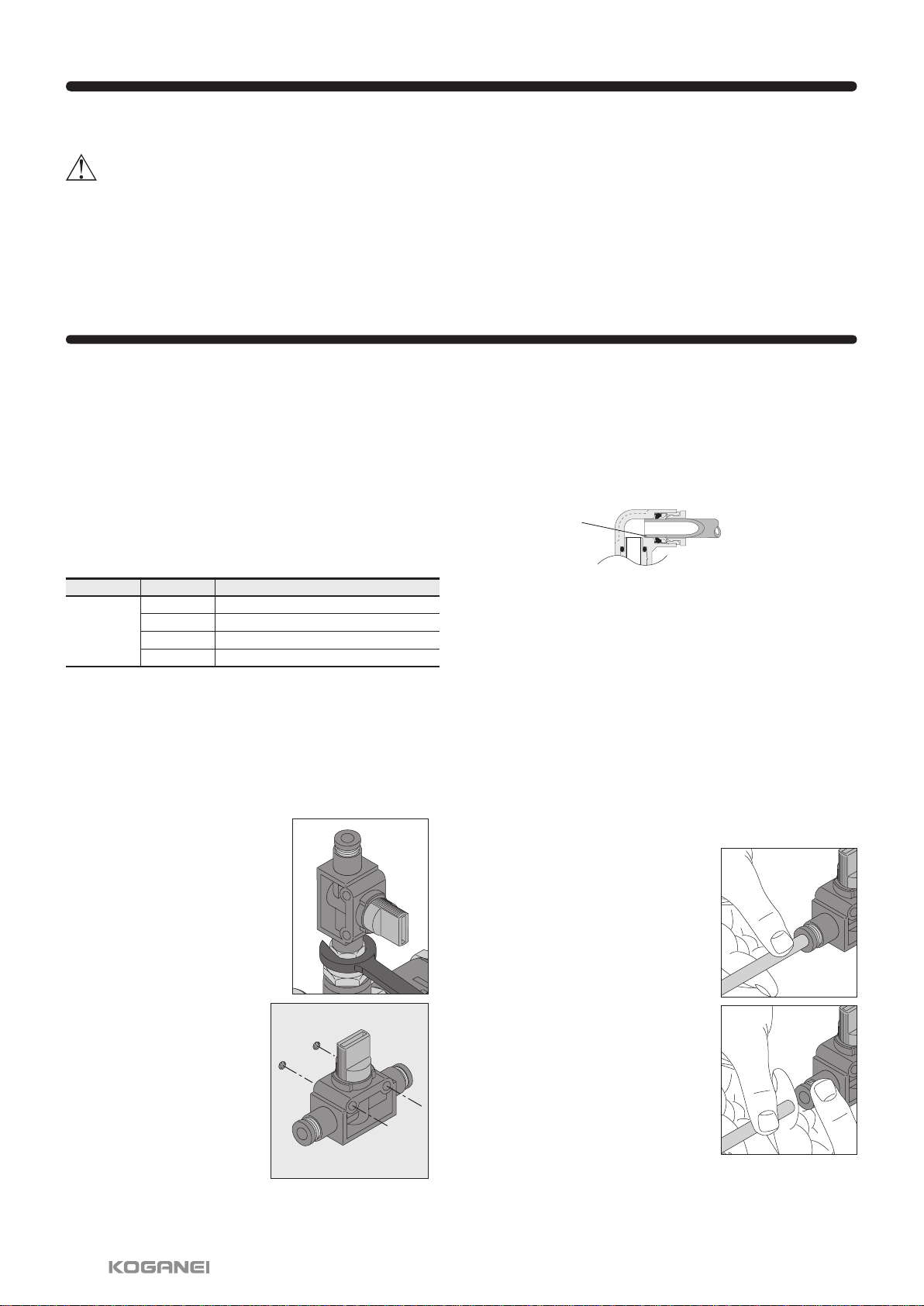
Precautions for mounting the body
①Use the appropriate tool to tighten the hex nuts on the hand
valve's tapered threads for pipes.
②Refer to the following table of recommended tightening
torques when tightening the threaded parts. If you use more
than the recommended torque when tightening the threaded
parts, you may cause leaks by damaging or deforming the
threads. Also, if you use less than the recommended torque
when tightening the threaded parts, it may result in
looseness or leaks.
Precautions for disconnecting fittings
Fixing
①Use the appropriate tool to remove the hex nuts from the
hand valve's tapered threads for pipes.
②Remove the sealant from the threads on the other parts. If
the sealant is stuck to the other parts, it may get into
peripheral devices and cause a malfunction.
Tapered threads
for pipes
Thread type Thread size
7 to 9 N•m [61.957 to 79.659 in•lbf]
12 to 14 N•m [106.212 to 123.914 in•lbf]
22 to 24 N•m [194.722 to 212.424 in•lbf]
28 to 30 N•m [247.828 to 265.530 in•lbf]
R1/8
R1/4
R3/8
R1/2
Tightening torque
Recommended tightening torque
Precautions for attaching tubes
①Confirm that the cut surface of the tube is cut straight across,
that the outer surface of the tube is not damaged, and that
the tube has not become oval shaped.
②When connecting tubes, if you do not insert the tube all the
way to the tube end, it may result in leaks.
③After installing the tube, pull on it to check that it does not
come off.
④Do not meaninglessly press on the release ring before
attaching a tube. Doing so may cause the tube to become
detached.
Precautions for removing tubes
①Before removing tubing, be sure to confirm that the pressure
inside the tubing is zero.
②Uniformly press the release ring inwards as far as it goes
and then pull out the tubing. If you do not fully press in on
the release ring, the tube may not come out, or the tubing
may become scratched causing debris to be left inside the
fitting.
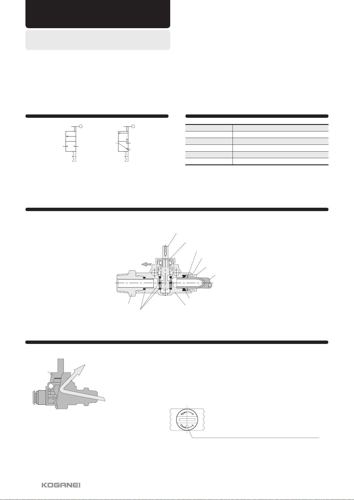
The safety precautions for the hand valves are shown below. Be sure to read the material in the front of the General Personal Catalog
regarding safety precautions other than those below.
Safety Precautions (Hand Valve)
CAUTION
●To operate the cap lever, turn it 90°until it stops completely. Insufficiencies in flow volume and continuity due to incomplete
switching may occur if it is not fully turned.
●Check the identification for bidirectional valves and tri-directional valves with the ②or ③engraved on the top of the cap lever.
●Install a filter for the vacuum on the suction side when negative pressure is being used. Erratic operation may be caused by dirt that
has been sucked into the product.
Tube end
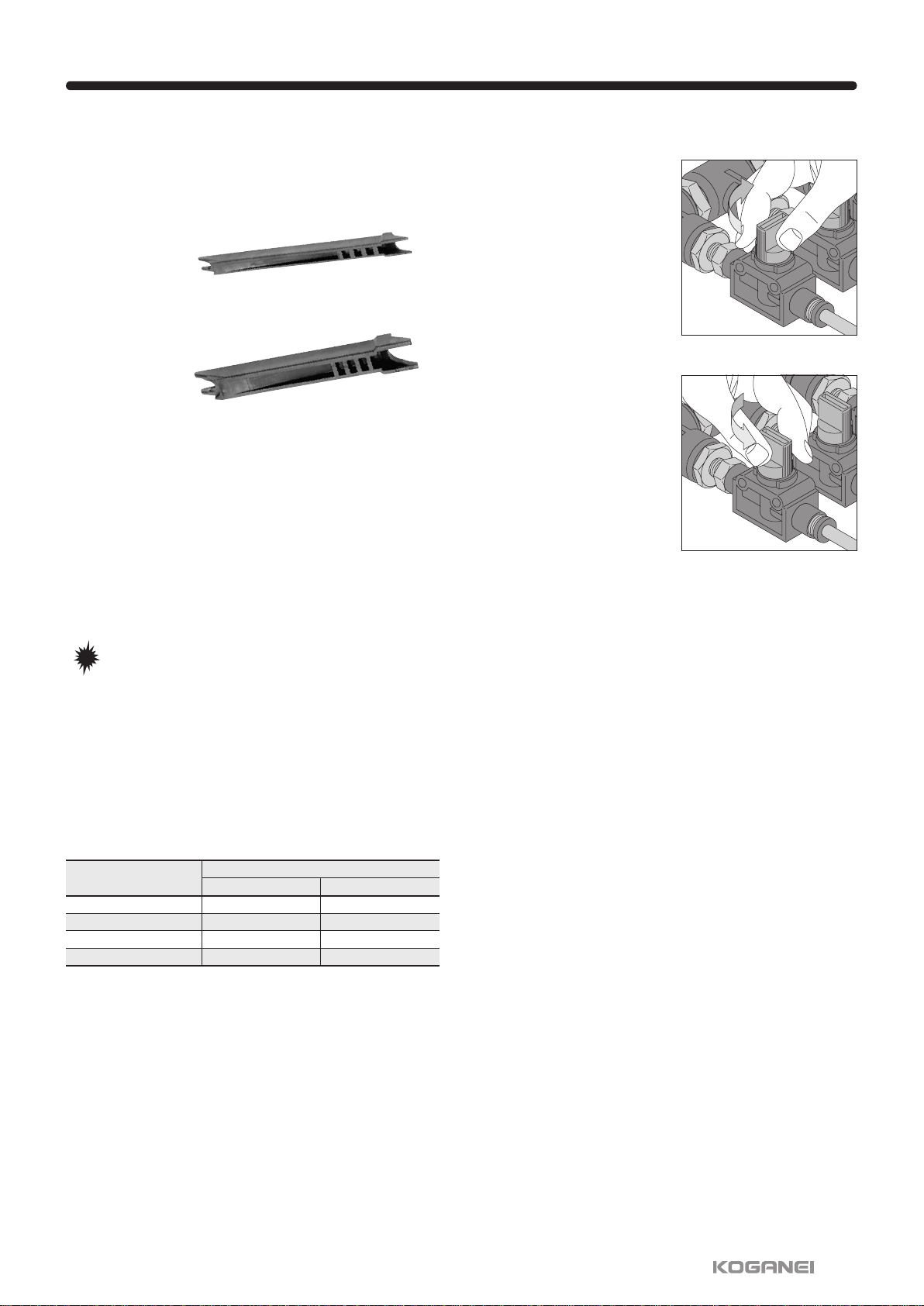
How to attach and detach tubes
①Attaching tubes
Hand valves are equipped with
lock claws that hold tubes in place
when they have been pushed all
the way to the end, and with an
elastic sleeve for sealing the
periphery around the tubes.
②Removing tubes
When removing a tube, pressing
the release ring opens the lock
claw and the tube can be pulled
out.
Be sure to stop the air before
removing tubes.
d
d
c
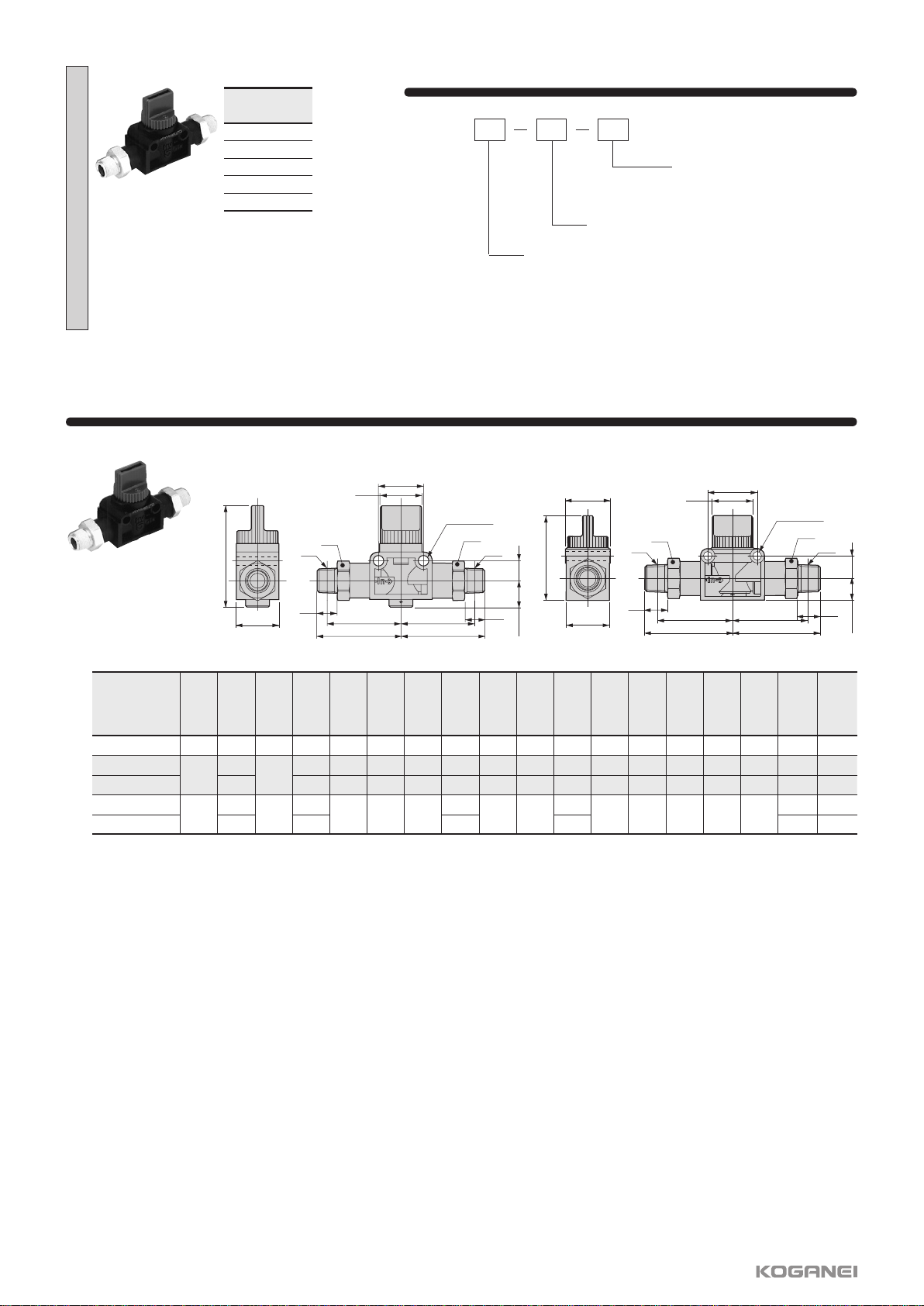
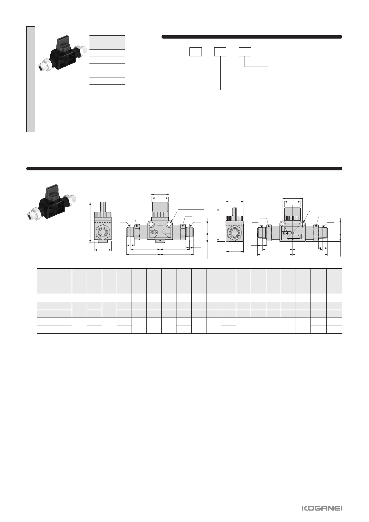
①Tightening the hex nuts
Tighten the hex nuts on straight A,
B, and nipple type hand valves
with a wrench.
②Fixing to the body
For union straight type hand
valves, use the fixing holes on
the plastic body and fix with
M4 screws. (Refer to the
diagra m fo r the exter n al
dimensions of the body for the
hole pitch to use for mounting.)
●Mounting ●Attaching and detaching tubes
032016

Handling Instructions and Precautions
If removing pipes is difficult because the piping space is very
constricted, consult your nearest Koganei sales office for
specialized tools that are available.
Specialized tools for removing tubes
●Usable tubes
Use of both nylon tubing and urethane tubing are supported.
Nylon tubing outside diameter precision should be within ±0.1
mm [±0.004 in] (nominal) for nylon tubing and within ±0.15 mm
[±0.006 in] (nominal) for urethane tubing. Use tubing with ovality
(difference between major axis and minor axis) within 0.2 mm
[0.008 in] (use of Koganei tubing is recommended).
Use of tubing that is not a Koganei genuine product or a
compatible (recommended) product may result in tube
disconnection, air leakage, or other problems. Be sure to check
on tubing before building a pneumatic system.
mm [in]
NOTE
1. Use tubing with an exterior that is not damaged. If tubing
becomes damaged after repeated use, cut off the damaged
portion.
2. Do not allow tubing to become severely bent or twisted
near the connection to a fitting. Such a condition creates
the risk of air leakage. The table below shows minimum
radius guidelines for nylon and urethane tubing.
3. Do not use extremely soft tubing, which causes a severe
drop in pull-out strength.
4. Before removing any tubes, always turn off the air supply.
Also, be sure to confirm that the air inside the pipes is
completely vented before starting.
●Operating the cap lever
When opening air
Turning the cap lever clock-
wise 90°until it stops causes
air to flow.
When closing the air
Turning the cap lever counter-
clockwise 90°until it stops
causes air to stop flowing.
Also, when using tri-directional
valves, the OUT side's residual
pressure is vented at the same
time when you are finished
turning the cap lever.
Tube size Minimum bending radius
Nylon tube Urethane tube
φ6 [0.236] 30 [1.181] 15 [0.591]
φ8 [0.315] 50 [1.969] 20 [0.787]
φ10 [0.394] 80 [3.150] 27 [1.063]
φ12 [0.472] 150 [5.9] 35 [1.378]
For φ3 [0.118], φ4 [0.157], and φ6 [0.236] tubes
Order codes: UJ-1
For φ6 [0.236], φ8 [0.315], φ10 [0.394], and φ12 [0.472] tubes
Order codes: UJ-2
032016
This manual suits for next models
4
Table of contents
Other Koganei Control Unit manuals

Koganei
Koganei ib-ZERO User manual

Koganei
Koganei CVR01 Series User manual

Koganei
Koganei KFPV050 Series User manual

Koganei
Koganei 010 SERIES User manual

Koganei
Koganei IB Series User manual

Koganei
Koganei 180 Series User manual

Koganei
Koganei KFPV050 Series User manual

Koganei
Koganei F Series User manual