Di,,erential
Assembly
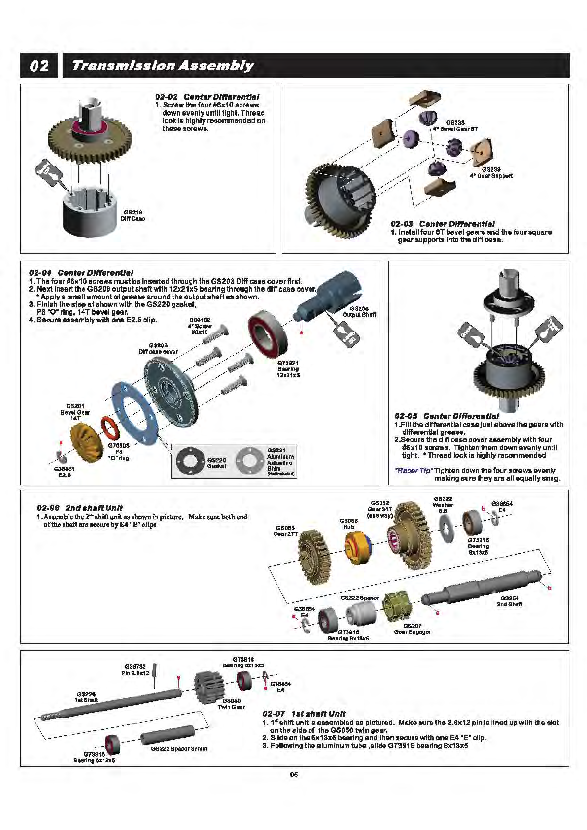
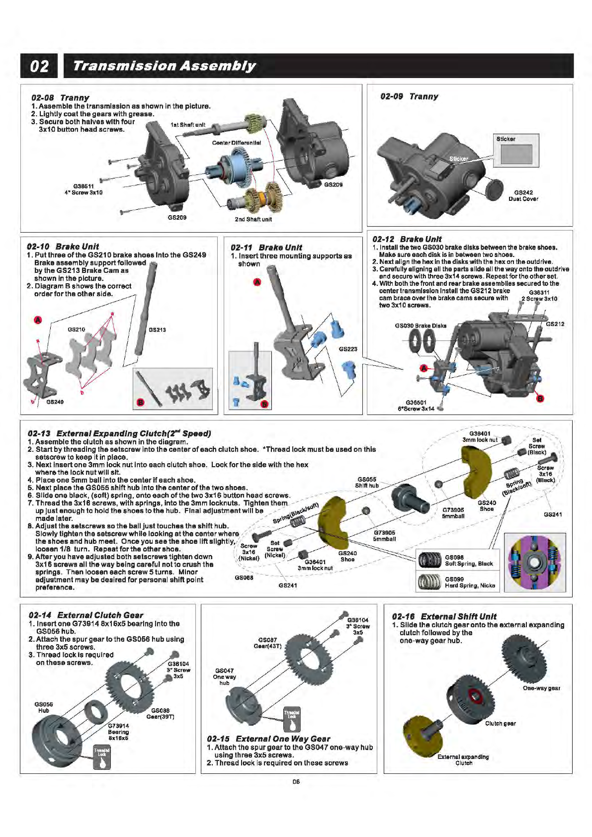
04-03 Differential
1.1nstall Bevel Gearinto GearSupport
2.Siidethe
unit
into designate
slotson thed
iff
case.
04-02 Differential
1.Screw the four#6x1 0 screws down evenly until tight.
Thread
lock
Ishighlyrecommended onthese screws.
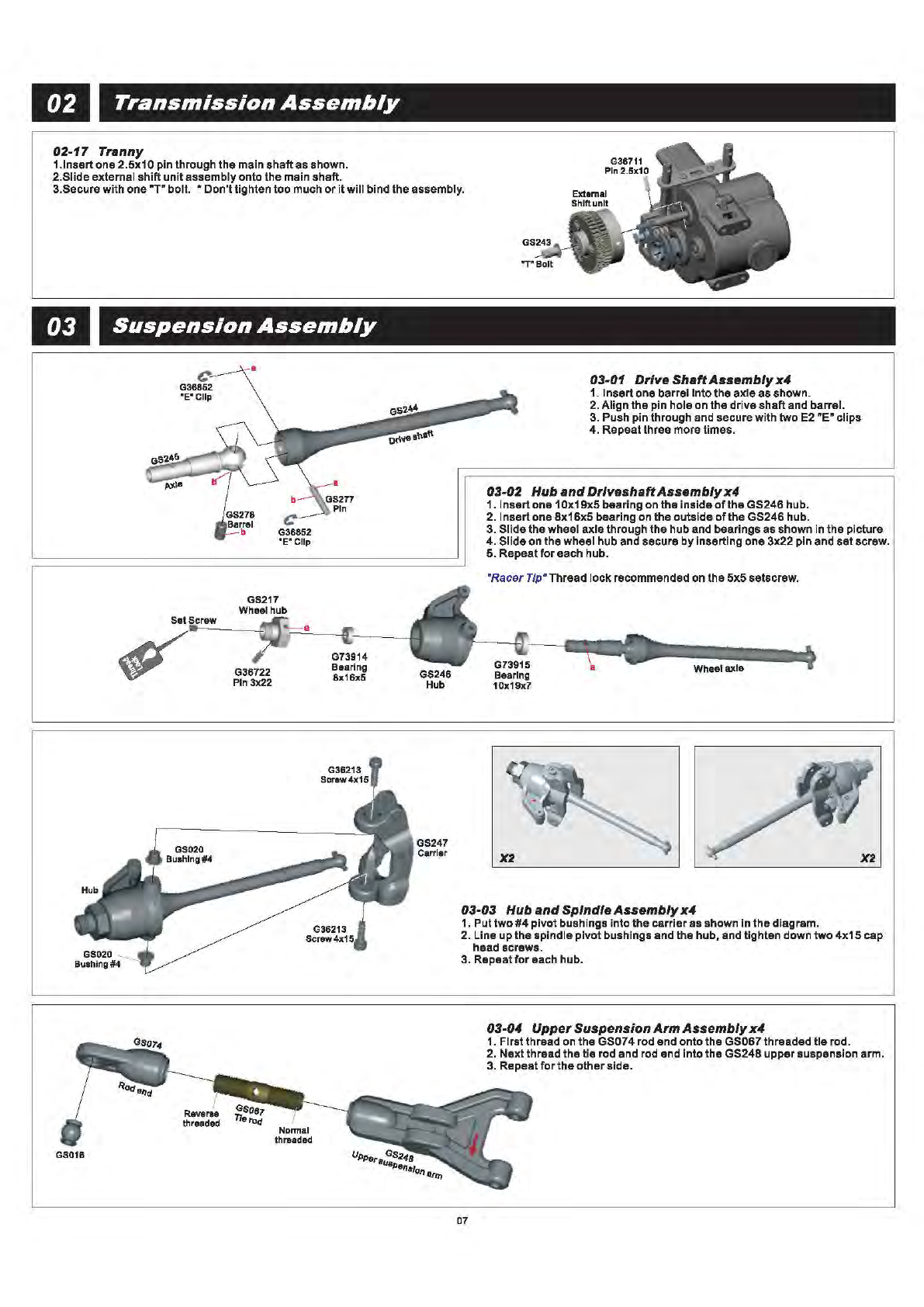
04-04 Differential
1.
Thefour#6x10
screws must
be
inserted
through
the
GS203 Diffcase coverfirst.
2. Next insertthe GS204
output
shaftwith
12x21x5bearing through the
dlff
case
cover. 0
O
~~~~~um
65220
Adjuating
Gasket
Shim
c_
_________
___;_(N_ot
---,lncludlld)
•
Apply
a small amount
of
grease around
the
output
shaftas shown.
3. Finishthe step at shown with the GS220
gasket, P8•o• ring, 14Tbevel gear.
4. Secure assemblywith one E2.5clip.
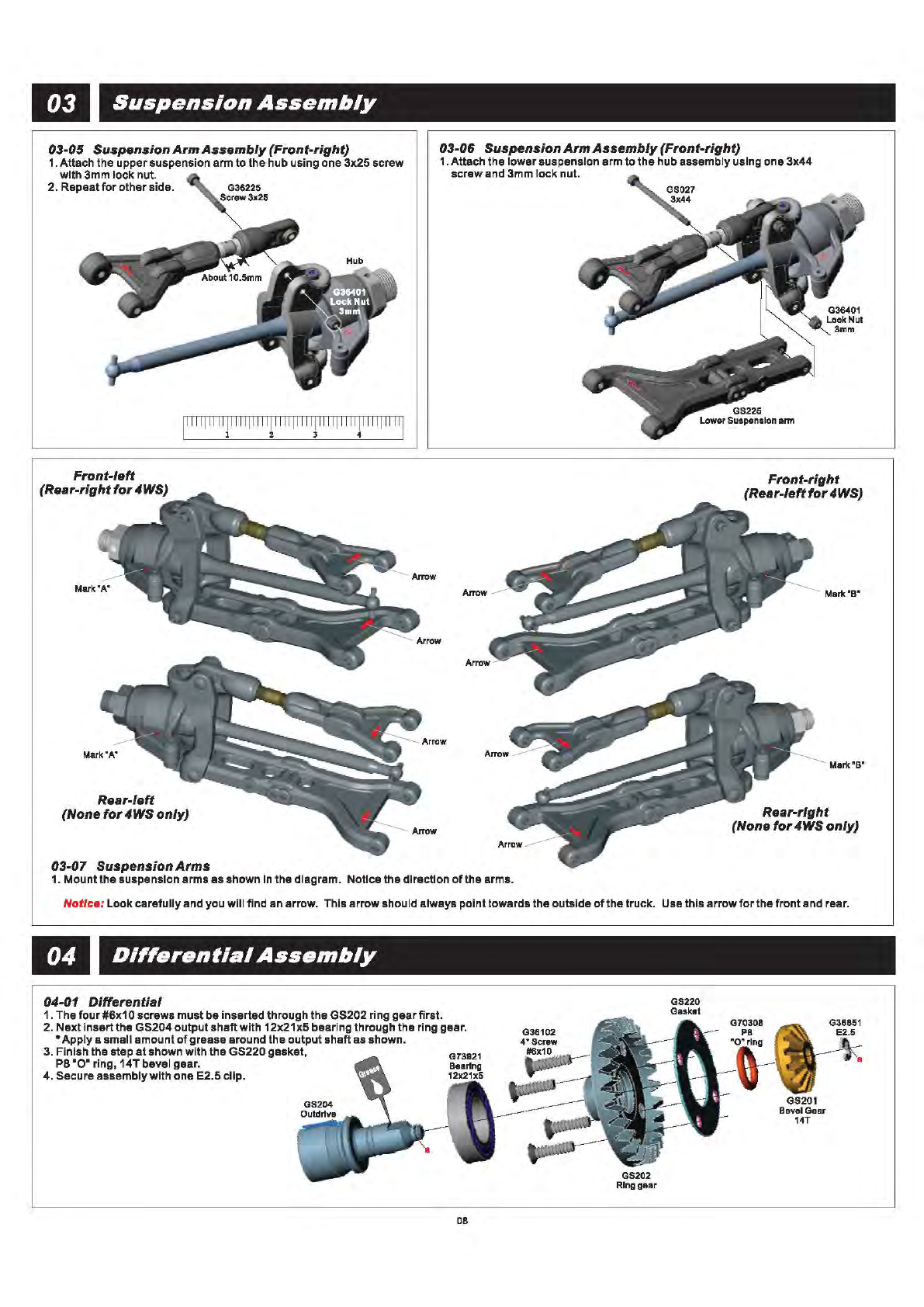
04-05 Differential
GS201
Baval Gaar
14T
1.
Fill thedifferential case
just
abovethe gearswith differential grease.
2. Securethe
diff
case coverassemblywith
four
#6x10 screws. Tighten
them downevenlyuntiltight. • Thread lockIshighlyrecommended.
"RacerTip"Tighten down the fourscrews evenly
makingsure they
are
all
equally snug.
Gear
Box
Unit
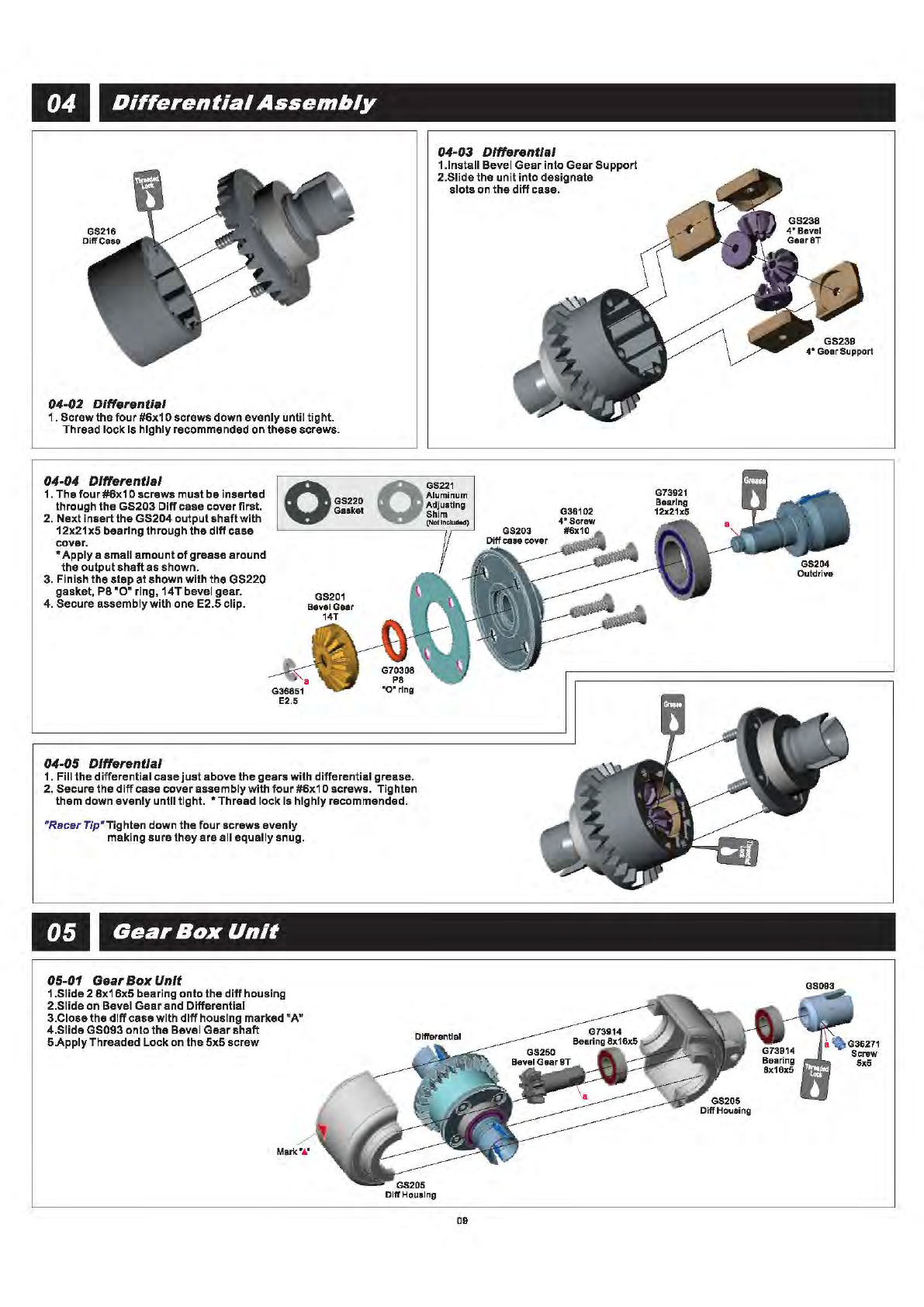
05-01 Gear
Box
Unit
1.Siide2 8x16x5bearing onto the
diff
housing
2.Siideon Bevel Gearand Differential
3.Ciosethe
dlff
casewith
dlff
housing marked
"A"
4.SiideGS093 ontothe Bevel
Gear
shaft
5.ApplyThreaded Lockon the 5x5 screw
09
G36102
G73921
Bearing
12x21xi;
GS204
Outdrive