Central Hydraulics 33610 User manual

R
TRANSMISSIONJACK
ASSEMBLYandOPERATINGINSTRUCTIONS
2000
rev 02/00

SPECIFICATIONS
Cylinder Extension 44" to 76"
Capacity 600 lbs.
Weight 58 lbs.
SAVE THIS MANUAL
You will need the manual for the safety warnings and cautions, assembly instructions, operating
procedures, maintenance procedures, trouble shooting, parts list, and diagram. Keep your invoice
with this manual. Write the invoice number on the inside of the front cover. Keep both this
manual and your invoice in a safe, dry place for future reference.
SAFETY WARNING & CAUTIONS
WARNING: When using hydraulic equipment, basic safety precautions should always be followed
to reduce the risk of personal injury and hazards due to over pressurization. READ ALL INSTRUC-
TIONS BEFORE USING THIS TOOL!
1. KEEP WORK AREA CLEAN. Cluttered areas invite injuries.
2. OBSERVE WORK AREA CONDITIONS. Do not use tools in damp, wet, or poorly lit locations.
Don’t expose to rain. Keep work area well lit.
3. KEEP CHILDREN AWAY. Children must never be allowed in the work area. Do not let them
handle machines, tools, or hoses.
4. STORE IDLE EQUIPMENT. When not in use, tools must be locked up in a dry location to inhibit
rust. Always lock up tools and keep out of reach of children.
5. DO NOT FORCE THE TOOL. It will do the job better and more safely at the rate for which it
was intended. Do not use inappropriate attachments in an attempt to exceed the tool’s capaci-
ties.
6. USE THE RIGHT TOOL FOR THE JOB. Do not attempt to force a small tool or attachment to
do the work of a larger industrial tool. Do not use a tool for a purpose for which it was not in-
tended.
7. DRESS PROPERLY. Do not wear loose clothing or jewelry as they can be caught in moving
parts. Non-skid footwear is recommended. Wear restrictive hair covering to contain long hair.
8. USE EYE AND EAR PROTECTION. Always wear ANSI approved chemical splash goggles
when working with chemicals. Always wear ANSI approved impact safety goggles at other
times. Wear a full face shield if you are producing metal filings or wood chips. Wear an ANSI
approved dust mask or respirator when working around metal, wood, and chemical dusts and
mists.
9. DO NOT OVERREACH. Keep proper footing and balance at all times. Do not reach over or
across running machines.
10. MAINTAIN TOOLS WITH CARE. Keep tools sharp and clean for better and safer performance.
Follow instructions for lubricating and changing accessories. The handles must be kept clean,
dry, and free from oil and grease at all times.
11. REMOVE ADJUSTING KEYS AND WRENCHES. Make it a habit to check that keys and
adjusting wrenches are removed from the tool or machine work surface before plugging it in.
12. AVOID UNINTENTIONAL STARTING. Do not carry any tool with your finger on the trigger.
13.STAY ALERT. Watch what you are doing, use common sense. Do not operate any tool when you
are tired.
#33610 Page 2

14. CHECK DAMAGED PARTS. Before using any tool, any part that appears damaged should be
carefully checked to determine that it will operate properly and perform its intended function.
Check for alignment and binding of moving parts; any broken parts or mounting fixtures; and
any other condition that may affect proper operation. Any part that is damaged should be prop-
erly repaired or replaced by a qualified technician. Do not use the tool if any switch does not
turn on and off properly.
15. REPLACEMENT PARTS AND ACCESSORIES. When servicing, use only identical replacement
parts. Use of any other parts will void the warranty. Only use accessories intended for use with
this tool. Approved accessories are available from Harbor Freight Tools.
16. DO NOT OPERATE TOOL IF UNDER THE INFLUENCE OF ALCOHOL OR DRUGS. Read
warning labels on prescriptions to determine if your judgment or reflexes are impaired while
taking drugs. If there is any doubt, do not operate the tool.
17. Failure to heed all instructions and warnings may result in death, personal injury, and/or
property damage.
18. When using the Transmission Jack, whenever possible, keep personnel clear of the area
underload.
19. Not to be used for aircraft purposes.
UNPACKING
When unpacking, check to make sure the following parts are included. If any parts are missing or
broken, please call Harbor Freight Tools at the number on the cover of this manual.
Item# Description Item# Description
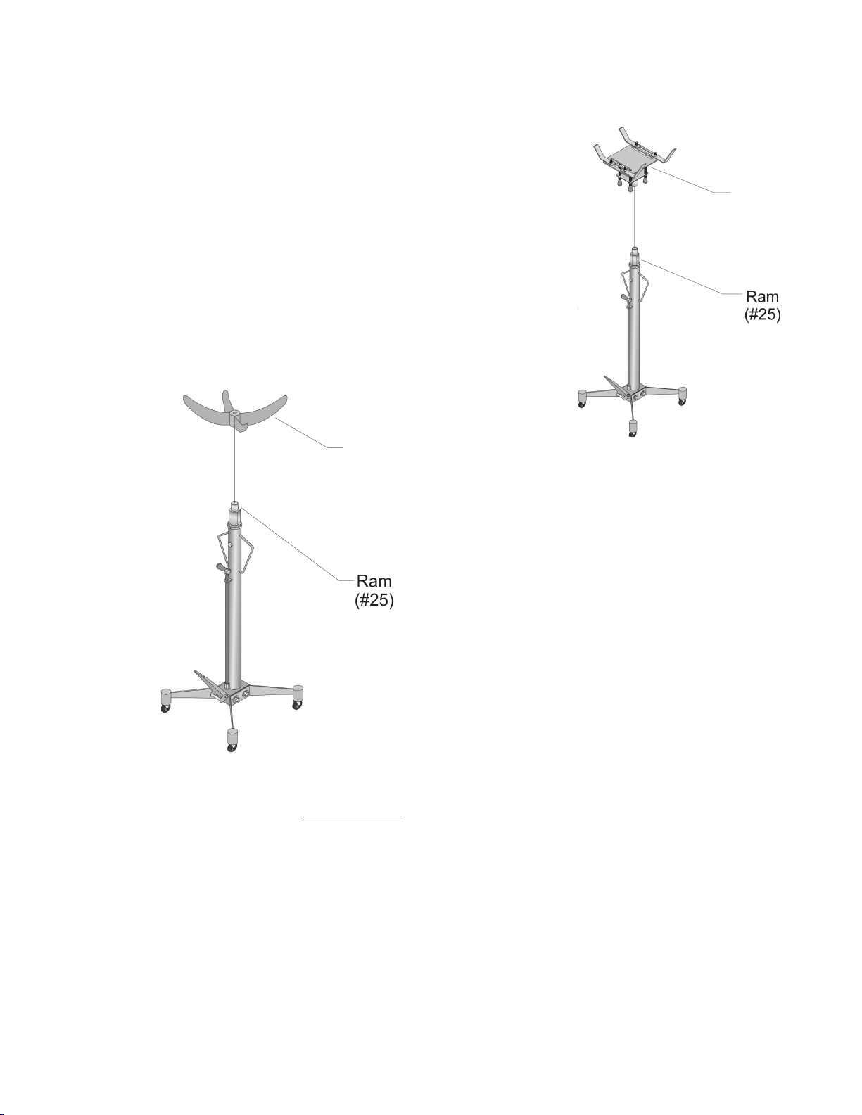
N/A Saddle Assembly N/A Leg Assembly
38 Saddle A 18 Reservoir Assembly
#33610 Page 3
WARNING:
ALWAYS EVALUATEYOUR TASK BEFORE USING THIS JACK. Thisjack isdesignedto support
a transmission or a differential as individual components. Assemblies such as a differential with
axle,ora transmission with bellhousing,canbe bulky and difficulttobalance on the jack’splatform
or cradle.
LIFTING OR SUPPORTING SUCH ASSEMBLIES, EVEN WITHIN THE WEIGHT LIMIT, CAN
CREATE AN OFF-BALANCE SITUATION, CAUSING THE JACK TO TIP OVER AND LEAD TO
SERIOUS PERSONAL INJURYOR PROPERTY DAMAGE.
The load should be evenly distributed on the jack, and should not extend beyond the area of the
castor wheelbase. Always use safety straps or chains to secure the load.
If you are working and the load becomes off-balance and/or the jack begins to tip over,
DO NOT ATTEMPT TO CATCH OR LIFT WHEN FALLING. SERIOUS PERSONAL INJURY
CAN BE SUFFERED! In this event, clear the area as quickly and safely as possible in order to
avoid injury from the falling load, including getting hit with flying fragments.
IF IN DOUBT ABOUT THE SAFETY OF YOUR PROJECT, WE ADVISE YOU TO HAVE THE
WORK DONE BY A PROFESSIONAL FAMILIAR WITH APPLICABLE SAFE PRACTICES.
REV 09/02 REV 03/04

ASSEMBLY
Step 1: Remove the four BOLTS (#35) and SPRING WASHERS (#13) from the BASE (#1) of the
Reservoir Assembly.
Step 2: Attach the Leg Assemblies to the BASE using the BOLTS and SPRING WASHERS from
Step 1 as shown in Figure 1. Tighten the BOLTS.
Figure 1 — Attaching Leg Assemblies
Step 3: Remove the NUTS (#44), Washers,
and BOLTS (#43) to remove the
STATIONARY PLATES (#42) from
the SADDLE (#40). The
STATIONARY PLATES are installed
upside down for shipping purposes.
Step 4: Reinstall the STATIONARY PLATES
using the NUTS, Washers,
and BOLTS as shown in Figure 2.
For Differential Service
Your Transmission Jack comes with two
different Saddles. SADDLE A (#38) is used to
remove and install Differentials.
blies
Figure 2-Installing the Stationary Plates
#33610 Page 4REV 09/02

Place the SADDLE A (#38) over the tip of the RAM (#25) as shown
in Figure 3.
Your Differential Jack is ready for use.
For Transmission Service
Your Transmission Jack comes with two different Saddles.
SADDLE (#40) is for use in removing and installing Transmissions.
Place the Saddle Assembly from Step 4 above onto the tip of the
RAM as shown in Figure 4.
Your Transmission Jack is ready for use.
Saddle B
(#39)
Figure 3--Placing Saddle B
Saddle A
(#38)
Figure 4--Placing Saddle A
OPERATION
Warning: Only use the Jack on a hard, flat and level surface. When not transporting
a load, block the wheels to prevent inadvertent movement.
Before use, make sure your vehicle is properly and safely suspended on an in-floor hydraulic lift.
You will not be able to use your Transmission Jack by raising the vehicle with a standard floor jack
and jack stands.
Make sure the Transmission or Differential you will be removing or intstalling does not exceed the
600 lbs. weight capacity of your Transmission Jack.
#33610 Page 5

Differential Removal
Step 1: Roll the Transmission Jack underneath the differential of your vehicle.
Step 2: Make sure the RELEASE VALVE (#31) is turned fully clockwise to close the BODY
RELEASE VALVE (#27).
Step 3: Raise the SADDLE A (#38) up under the differential by stepping on the PEDAL PUMP
PISTON (#11) as shown in Figure 5.
Figure 5--Raising the Saddle
Step 4: When the SADDLE A makes contact with the differential, make sure the differential is
properly and safely positioned and centered within the cradle arms of the SADDLE A. If in
doubt, reposition the SADDLE A.
Step 5: Lift the SADDLE A an additional inch after contact is made between the differential and
the SADDLE A. This will remove the load of the differential from the vehicle’s chassis.
The weight of the differential is now supported by the Transmission Jack.
Step 6: Remove the differential attachment points as appropriate to your vehicle. Refer to your
vehicle’s Service Manual.
It is recommended that you have an assistant present to help steady the differential assembly as
you remove the attaching hardware. Use caution when loosening the differential from the chassis.
Make sure the differential does not move while it is being supported by the Transmission Jack.
Step 7: When you are ready to lower your differential, make sure there is nothing restricting the
free downward movement of your differential.
Step 8: To lower the differential, turn the RELEASE VALVE counterclockwise slowly as shown in
Figure 6. Do not lower the differential in one quick drop as you may upset the balance of
the differential within the SADDLE A.
#33610 Page 6

Release Valve Be aware of dynamic loading! If you
drop an item onto the jack, it may create for
a brief instant, an excess load. The Jack is
designed for 600 Lbs. maximum load only;
do not exceed.
Step 9: Move the Transmission Jack from beneath your vehicle. Position the Transmission Jack
for convenience. You may perform needed maintenance of the differential while it is on
the Transmission Jack.
Figure 6--Lowering the Saddle
Differential Installation
Step 1: Position the Transmission Jack underneath your supported vehicle.
Step 2: Turn the RELEASE VALVE clockwise to close the BODY RELEASE VALVE.
Step 3: Raise the SADDLE A by stepping on the PEDAL PUMP PISTON.
Step 4: When the differential is in the proper position, reattach the differential to your vehicle.
Step 5: After the differential is safely attached to your vehicle, lower the SADDLE A by turning the
RELEASE VALVE counterclockwise.
Step 6: Inspect the vehicle to insure the differential has been properly installed.
Transmission Removal
Step 1: Roll the Transmission Jack underneath the transmission of your vehicle.
Step 2: Make sure the RELEASE VALVE (#31) is turned fully clockwise to close the BODY RE-
LEASE VALVE (#27).
#33610 Page 7
Warning:

Step 3: Raise the SADDLE (#40) up under the transmission by stepping on the PEDAL PUMP
PISTON (#11) as shown in Figure 7.
Figure 7--Raising the Saddle
Step 4: When the vehicle is safely raised, maneuver the Transmission Jack
underneath the vehicle. You will want to position the Transmission Jack so
that the pairs of STATIONARY PLATES (#42) will hold the forward and
rearward ends of the transmission, respectively, as shown in Figure 8.
s
Figure 8--Placing the Stationary Plates
Step 5: If necessary, loosen the NUTS (#44) to adjust the positions of the
STATIONARY PLATES to best cradle the transmission. Tighten the NUTS
before continuing.
#33610 Page 8

Step 6: Raise the SADDLE (#40) of the Transmission Jack by pressing the PEDAL PUMP PIS-
TON (#11). Raise the SADDLE until it makes contact with the transmission.
Step 7: Make sure the STATIONARY PLATES are properly positioned to securely cradle the
transmission. Adjust as necessary; See Step 5 above.
Step 8: Raise the SADDLE an additional half-inch. This will transfer the weight of the transmis-
sion to the Transmission Jack.
Step 9: Following the Steps in your vehicle’s Service Manual, remove the driveshaft, and any and
all mounting bolts and/or nuts.
Step 10: Depending on the type of transmission, you may need to move the Transmission Jack and
transmission rearward a few inches to free the input shaft of the transmission, if so
equipped.
Warning: Only use the Jack on a hard, flat and level surface. When not transporting a
load, block the wheels to prevent inadvertent movement.
Step 11: With the transmission free from the vehicle and resting between the STATIONARY
PLATES, you may lower the SADDLE by slowly turning the RELEASE VALVE
counterclockwise. The transmission is heavy and care should be taken when lowering to
prevent it from rocking.
Step 12: Roll the Transmission Jack from beneath the vehicle. Position the Transmission Jack for
convenience. You may perform needed maintenance of the transmission while it is on the
Transmission Jack.
Step 1: Position the Transmission Jack underneath your supported vehicle.
Step 2: Turn the RELEASE VALVE clockwise to close the BODY RELEASE VALVE
Transmission Installation
Step 3: Raise the SADDLE by stepping
on the PEDAL PUMP PISTON.
Step 4 :When the transmission is in the proper
position, reattach the transmission to your
vehicle.
Step 5:If necessary, you can adjust the
angle and attitude of the transmission
by turning the ADJUSTABLE
SCREWS (#41). Thread the
ADJUSTABLE SCREWS clockwise
(as viewed from below) to raise up
that portion of the SADDLE. Thread
the ADJUSTABLE SCREWS
counterclockwise (as viewed from below)
to lower that portion of the SADDLE.
Thread the ADJUSTABLE SCREWS
counterclockwise (as viewed from below)
to lower that portion of the SADDLE as shown in Figure 9.
Figure 9--Adjusting the Angle and Attitude
#33610 Page 9

Your transmission should now be in position to allow you to mount it to the engine and vehicle. If
the transmission is not in correct position, repeat Steps 3-5 as needed.
Step 6: After the transmission is safely attached to your vehicle, lower the SADDLE by turning the
RELEASE VALVE counterclockwise.
Step 7: Inspect the vehicle to insure the transmission has been properly installed.
MAINTENANCE
Bleeding the Transmission Jack
Should you experience little lifting ability with your Transmission Jack, follow the Steps below to
bleed the Transmission Jack. Make sure the Transmission Jack is not lifting anything while per-
forming Maintenance.
Step 1: Unscrew and remove the AIR VENT VALVE (#34) from the RESERVOIR (#18) as shown
in Figure 10.
Step 2: Raise the Jack’s RAM up to the full height.
Step 3: Turn the RELEASE VALVE (#31) counterclockwise to open the BODY RELEASE VALVE
(#27). Quickly press the RAM (#25) down into the RESERVOIR.
Step 4: Insert the AIR VENT VALVE back into the RESERVOIR. Tighten.
Your Transmission Jack has been bled.
Figure 10--Removing the Air Vent Valve
#33610 Page 10

Seal Replacement
Replacement O-RINGS and SEALS can be purchased if you need to have your jack serviced. If
you need to have your jack serviced, take it to a qualified mechanic along with your O-RINGS and
SEALS. The Transmission Jack cannot be user serviced.
Lubrication
Lubricate the following points before first use and at least twice per month (more often during heavy
use) as shown in Figure 11.
Figure 11--Lubrication Points
#33610 Page 11

PARTS LIST
Item# Description Qty Item# Description Qty
1 Base 1 23 O-Ring 1
2 Ball 1/4" 2 24 Dust Seal 1
3 Ball 3/8" 1 25 Ram 1
4 Snap-Ring C 1 26 Washer 1
5 Spring 1 27 Body Release Valve 1
6 Seal 1 28 O-Ring 1
7 Bushing 1 29 Release Rod 1
8 O-Ring 1 30 Nut M8 1
9 O-Ring 1 31 Release Valve 1
10 Pump Piston 1 32 Gripper 1
11 Pedal Pump Piston 1 33 O-Ring 1
12 Bolt M10X60 1 34 Air Vent Valve 1
13 Spring Washer 1 35 Bolt M10X15 4
14 Nut M10 1 36 Leg 2
15 Cylinder 1 37 Castor 4
16 Filter 1 38 Saddle A 1
17 Flat O-Ring 1 39 Saddle B 1
18 Reservoir 1 40 Saddle 1
19 Top Nut 1 41 Adjustable Screw 4
20 Seal 1 42 Stationary Plate 4
21 Back Up Ring 1 43 Bolt M12X25 4
22 O-Ring 1 44 Nut M12 4
#33610 Page 12
PLEASE READ THE FOLLOWING CAREFULLY
THE MANUFACTURER AND/OR DISTRIBUTOR HAS PROVIDED THE PARTS
DIAGRAM IN THIS MANUAL AS A REFERENCE TOOL ONLY. NEITHER THE
MANUFACTURER NOR DISTRIBUTOR MAKES ANY REPRESENTATION OR
WARRANTY OF ANY KIND TO THE BUYER THAT HE OR SHE IS QUALIFIED TO
MAKE ANY REPAIRS TO THE PRODUCT OR THAT HE OR SHE IS QUALIFIED
TO REPLACE ANY PARTS OF THE PRODUCT. IN FACT, THE MANUFACTURER
AND/OR DISTRIBUTOR EXPRESSLY STATES THAT ALL REPAIRS AND PARTS
REPLACEMENTS SHOULD BE UNDERTAKEN BY CERTIFIED AND LICENSED
TECHNICIANS AND NOT BY THE BUYER. THE BUYER ASSUMES ALL RISK
AND LIABILITY ARISING OUT OF HIS OR HER REPAIRS TO THE ORIGINAL
PRODUCT OR REPLACEMENT PARTS THERETO, OR ARISING OUT OF HIS
OR HER INSTALLATION OF REPLACEMENT PARTS THERETO.

ASSEMBLYDIAGRAM
#33610 Page 13
Table of contents
Other Central Hydraulics Jack manuals