Page 2SKU 94682 For technical questions, please call 1-800-444-3353.
SPECIFICATIONS
Capacity Of Each Hydraulic
Wheel Dolly
1,500 lb. Weight Capacity Per Dolly, Each Dolly Fits Tires
Up to 10” Wide
Construction All Steel Construction, Aluminum Rollers, Rubber O-rings
Castor Dimensions 4” Diameter x 1-3/8” Wide x 4-3/4” Total Height
Roller Dimensions 10-5/8” Long x 2-3/4” Diameter x 4-3/8” Total Height
Distance Between Rollers 9-7/8’” Minimum to 20-3/4” Maximum
Roller Locking Width 10”
Ram Travel 10-7/8”
Ram Diameter 15/16”
Weight Per Wheel Dolly 40.7 lb.
SAVE THIS INSTRUCTION MANUAL
You will need this instruction manual for the safety warnings and precautions, inspection, maintenance,
and cleaning procedures. Keep your invoice with this instruction manual. Write the invoice number
on the front page. Keep this instruction manual and invoice in a safe and dry location for future refer-
ence.
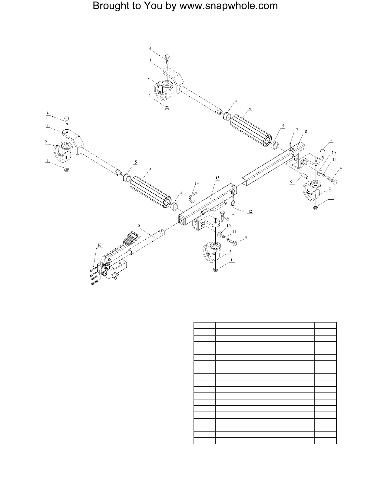
UNPACKING
When unpacking, check to make sure the parts shown on this instruction manual are included. If any
parts are missing or broken, please call Harbor Freight Tools at the telephone number shown on the
front page of this manual.
GENERAL SAFETY WARNINGS AND PRECAUTIONS
1. KEEP WORK AREA CLEAN AND DRY. Cluttered, damp or wet work areas invite injuries.
2. USE EYE PROTECTION. Wear ANSI approved safety impact eye glasses when using this
product. ANSI approved safety impact eye glasses are available from Harbor Freight Tools.
3. DO NOT ALLOW CHILDREN IN THE WORK AREA. Keep away from children. Do not allow
children to play with this product.
4. CHECK FOR DAMAGED PARTS. Before using this product, carefully check that it will operate
properly and perform its intended function. Check for damaged parts and any other condi-
tions that may affect the operation of this product. Replace or repair damaged or worn parts
immediately.
5. REPLACEMENT PARTS AND ACCESSORIES. When servicing, use only identical replace-
ment parts.
6. MAINTAIN THIS PRODUCT WITH CARE. Keep this product clean and dry for better perfor-
mance.
7. USE THE RIGHT PRODUCT FOR THE RIGHT JOB. There are certain applications for which
this product was designed. Do not use small equipment, tools or attachments to do the work
of larger industrial equipment, tools or attachments. Do not use this product for a purpose for
which it was not intended.
Brought to You by www.snapwhole.com