CENTRAL A-1 User manual

1
Manufactured by: Central Sprinkler Company
451 North Cannon Avenue, Lansdale, Pennsylvania 19446
1⁄2" (12.7 mm)
Orifice
Non-Adjustable
Dry Pendent
Automatic
Sprinkler
A-1 Dry Pendent
No.5-1.0
Model A-1
The Model A-1 Dry Pendent Sprin-
klers are designed for use in special
applications such as freezing environ-
ments or in conditions where sedi-
ment or foreign material might accu-
mulate in ordinary drop nipples.
The Model A-1 is Listed by FM for
use as a standard sprinkler in accor-
dance with FM Loss Prevention Data
Sheets and current NFPA 13 Stan-
dards. The spacing, deflector dis-
tances and associated installation cri-
teria shall be in accordance with
these standards.
Operation: A fusible alloy is sealed
into a bronze center strut by a stain-
less steel ball. When the alloy melts
at its rated temperature, the ball is
forced down, releasing the strut and
allowing the seat of the sprinkler to
fall away. This action causes a guide
tube contained within the barrel of the
dry sidewall to reposition itself,
releasing ball bearings holding the cap
(plunger) in place at the other end of
the dry sidewall barrel. The cap
(plunger) is then discharged from the
barrel assembly, out the open sprin-
kler, followed by discharge of water.
Product
Description Technical
Data
Model: A-1
Style: Flush, Recessed, or Extended
Wrench: Apply a pipe wrench to the upper
brass thread connector only.
Orifice Size: 1⁄2"
(12.7 mm)
Maximum Length: 36"
(914.4 mm)
K-Factor: 5.6
(80.8 metric)
Nominal
Maximum Working Pressure:
175 psi
(12.1 bar)
Factory Hydro Test:
100% at 500 psi
(34.5 bar)
Dry Pendent
Flush, Recessed, & Extended
Automatic Sprinkler
7-99
* The Central A-1 Flush & Extended Dry Pendent Sprinklers are Factory Mutual Approved for
use in Light Hazard and Ordinary Hazard Occupancies. Central A-1 Recessed Dry Pendent
Sprinklers are Factory Mutual Approved for use in Light Hazard only. The FM Approvals for
Ordinary Hazard Occupancies is limited to wet pipe sprinkler systems and preaction systems
qualifying as wet pipe systems.
Approvals
Brass or
Chrome Plated FM 1"
(25 mm)
1"
(25 mm)
A-1
Flush &
Extended
A-1
Recessed
Pendent
Style Temperature
Rating Standard
Finishes Approvals * Thread
Size
"NPT"
165°F/74°C
212°F/100°C
286°F/141°C
FM
Brass or
Chrome Plated
165°F/74°C
212°F/100°C
OBSOLETE

Figure 1 Model A-1
Non-Adjustable Dry Pendent
Flush, Recessed
Figure 2 Model A-1
Non-Adjustable Dry Pendent
Extended
Caution: See step one of installation sequence for appropriate fitting requirements.
Ordering Length for Dry Pendent Heads
Flush — The “A” dimension is measured from the face of the tee to the finished ceiling. This is only approximately flush. Order
to the nearest 1⁄4"
(6.4 mm)
. Minimum “A” dimension is 21⁄2"
(63.5 mm)
.
Recessed — The “A” dimension is measured from the face of the tee to the finished ceiling. Minimum “A” dimension is 3"
(76.2 mm)
. Adjustment is +1⁄4"
(6.35 mm)
.
Extended — The “A” dimension is measured from the face of the tee to the finished ceiling. Order to the nearest 1⁄4" (6.4 mm).
Minimum “A” dimension is 0". Adjustment is +7⁄16"
(11.1 mm)
.
Finished
Ceiling LIne
“A”
Dimension
(order length)
3 3/4"
(95 mm)
Min.
4 5/8"
(118 mm)
Max.
MainTube
1"
(25 mm)
N.P.T.
Thread
2"
(50 mm)
“A”
Dimension
(order length)
1 1/2"
(40 mm)
Min.
2"
(50 mm)
Max.
Ceiling
Escutcheon
Plate
MainTube
1"
(25 mm)
N.P.T.
Thread
2 1/4
(57 mm)
3 3/16
(81 mm)
Finished Ceiling
Line
OBSOLETE

Design Requirements—Standard Applications
The Model A-1 Flush, Recessed, and Extended Dry Pendent Sprinklers are
intended for standard area coverages and standard flow and pressure require-
ments as specified in current NFPA Standards.
Design
Data
Sprinklers must be handled care-
fully. They must not be transported
or stored where ambient temperature
may exceed 100°F/38°C. For best
results, store them in a dry, cool
location in the original shipping
package.
Do not install sprinklers that have
been dropped or visibly damaged.
Sprinklers should never be painted,
coated, plated or altered in any other
way from manufactured condition or
they may not function properly. Any
sprinklers altered in such a manner
must be replaced.
The owner is responsible for the
proper operating condition of all fire
protection devices and accessories.
The NFPA standard 25 entitled,
“Inspection, Testing and Maintenance
of Water-Based Fire Protection
Systems”
, contains guidelines and
minimum maintenance requirements.
Furthermore, the local
Authority
Having Jurisdiction
may have addi-
tional regulations and requirements
for maintenance, testing, and inspec-
tion that must be obeyed.
It is advisable to have sprinkler
systems inspected regularly by a
qualified inspection service. Length
Care &
Maintenance
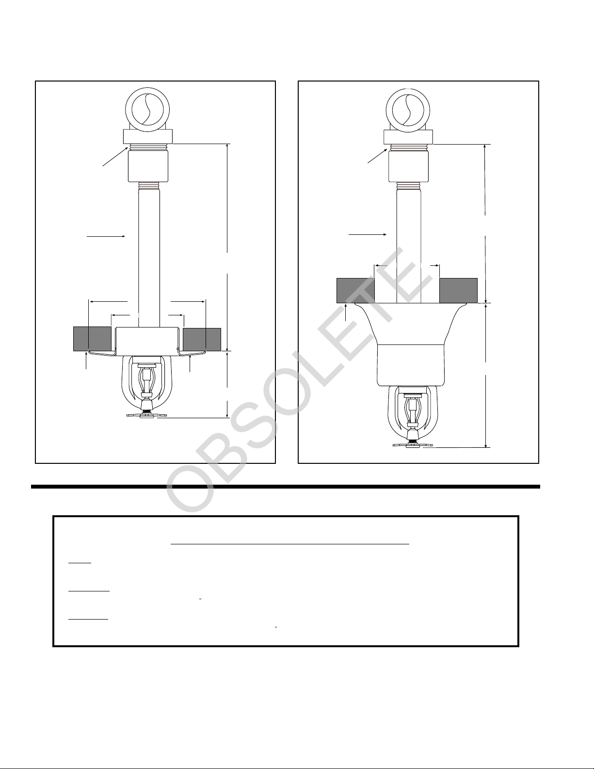
Installation Installation Sequence
Step 1. The unit should be
installed into a 1 inch NPT
threaded tee fitting conforming to
ANSI B16.3 for malleable iron and
ANSI B16.4 for cast iron threaded
fittings. Do not install into any
other type fitting without
consulting the Technical Services
department. Use of an improper
fitting can result in the failure of
the dry sprinkler to operate due to
binding of the plug or leakage
caused by insufficient engagement
of the threads into the fitting. In
scenarios with dry systems
subject to freezing conditions, the
use of an improper fitting can
result in the formation of an ice
plug on top of the dry pendent
plug if the plug does not extend
sufficiently into the fitting.
Step 2. Use only a non-hardening
pipe joint compound or Teflon* tape.
Apply only to the male threads.
Step 3. Hand tighten the sprinkler
into the fitting. The Model A-1 Dry
Pendent is installed by using a pipe
wrench at the upper brass thread
connector of the dry pendent. Use
the appropriate Wrench to tighten the
unit in the fitting. A leak tight joint
requires only 7 to 14 ft. lbs. (9.5 to
19.0 Nm) of torque; a tangential force
of 14 to 28 lbs. (62.3 to 124.5 N)
delivered through a 6" handle will
deliver adequate torque. Torque
levels over 40 ft. lbs. (54.4 Nm) may
twist the head in the main tube,
damaging the seal.
Step 4. To install the escutcheon
plate, align it with and push it over the
sprinkler body and into the upper
All Model A-1 Dry Pendent Auto-
matic Sprinklers must be installed
according to current NFPA 13 Stan-
dards.
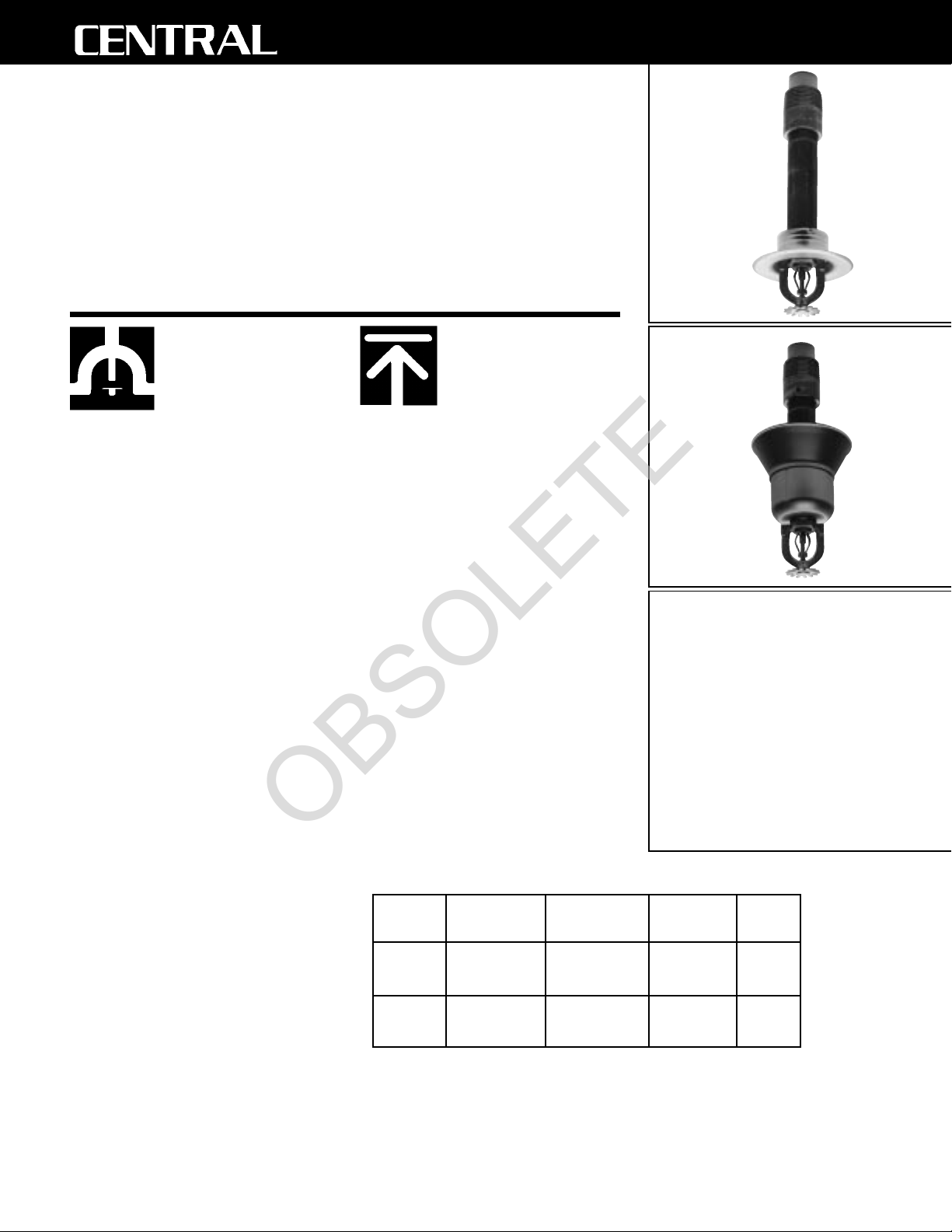
Dry Pendent sprinklers are de-
signed to prevent water from accumu-
lating in the drops to sprinklers. To
accomplish this, they have a fitting
that protrudes into the branch line
with a cap (plunger) assembly. This
prevents the possibility of water
freezing in the drop to the pendent
sprinkler, creating an ice plug. Dry
Sprinklers should be installed in a
tee. (See Step 1)
Deviations from these require-
ments and standards or any alteration
to the sprinkler itself will void any
warranty made by Central Sprinkler
Company. In addition, installation
must also meet local government
provisions, codes and standards as
applicable.
Check for the proper model, style,
orifice size, and temperature rating
prior to installation. Install sprinklers
after the piping is in place to avoid
mechanical damage; replace any
damaged units. Wet pipe systems
must be protected from freezing.
Upon completion of the installation,
the system must be tested per
recognized standards.
In the event of a thread leak,
remove the unit, apply new pipe joint
compound or tape, and reinstall.
*Teflon is a trademark of the DuPont Corp.
support piece until the outer edge of
the escutcheon meets the mounting
surface.
Do not over- or under-tighten the
sprinkler to compensate for
inaccurate escutcheon plate
adjustment.
Caution: Special care must be
taken when installing with a CPVC
system. Sprinklers must be installed
after the manufacturer's recom-
mended setting time for the primer
and cement to ensure that neither
accumulate within the sprinkler.
Special care must be taken when
installing with a copper system.
Sprinklers must be installed only after
the inside of the sprinkler drop and
associated fittings have been wire
brushed to remove any flux. Residual
flux can cause corrosion and in
extreme cases can impair proper
sprinkler operation.
OBSOLETE

of time between such inspections can
vary due to accessibility, ambient
atmosphere, water supply, and site
activity.
Do not attempt to re-assemble or
otherwise reuse a sprinkler that has
operated. Replace any sprinkler ex-
hibiting corrosion or damage; always
use new sprinklers of the same orifice,
style, and temperature rating as re-
placements.
Because the discharge pattern is
critical to protection of life and prop-
erty, nothing should be hung or at-
tached to the sprinkler unit that would
disrupt the pattern. Such obstructions
must be removed. In the event that
construction has altered the original
configuration, additional sprinklers
should be installed to maintain the
protection level.
Do not attempt to replace sprinklers
without first removing the fire protec-
tion system from service. Be certain
to secure permission from all
Authori-
ties Having Jurisdiction
, and notify all
personnel who may be affected during
system shutdown. A fire watch during
maintenance periods is a recom-
mended precaution.
To remove the system from service,
first refer to the system operating
guide and valve instruction. Drain
water and relieve pressure in the
pipes. Remove the existing unit and
install the replacement, using only the
recommended sprinkler wrench. Be
certain to match model, style, orifice,
and temperature rating.
Ordering
Information
©1999 Central Sprinkler Company
Printed in U.S.A.
Ordering Information: When
placing an order, indicate the full
product name. Please specify the
quantity, model, style, orifice size,
temperature rating, sprinkler finish,
and escutcheon finish, and required
“A” Dimension.
See page 2 for “A” Dimension infor-
mation.
Availability and Service: Central
sprinklers, valves, accessories and
other products are available through-
out the U.S. and Canada, and inter-
nationally, through a network of
Central Sprinkler distribution centers.
You may write directly to Central
Sprinkler Company, or call (215)
362-0700 for the distributor nearest
you.
Patents: Patents are pending.
Conversion Table:
1 inch = 25.400 mm
1 foot = 0.3048 m
1 pound = 0.4536 kg
1 foot pound = 1.36 Nm
1 psi = 6.895 kpa
= 0.0689 bar
= 0.0703 kg/cm2
1 U.S. gallon = 3.785 dm3
= 3.785 liters
Conversions are approximate.
A-1 Dry.2
A fire protection system that has
been shut off after an activation
should be repaired and returned to
service immediately. Inspect the entire
system for damage and replace or
repair as necessary. Sprinklers that
did not operate but were subjected to
corrosive elements of combustion or
excessive temperatures should be
inspected, and replaced if need be.
The
Authority Having Jurisdiction
will
detail minimum replacement require-
ments and regulations.
Guarantee: Central Sprinkler
Company will repair and/or replace
any products found to be defective in
material or workmanship within a
period of one year from the date of
shipment. Please refer to the current
Price List for further details of the
warranty.
Central Sprinkler Company
451 North Cannon Avenue, Lansdale, PA 19446
PHONE (215) 362-0700
FAX (215) 362-5385
OBSOLETE
Other CENTRAL Irrigation System manuals

CENTRAL
CENTRAL ELO-231 User manual

CENTRAL
CENTRAL ESFR-1 User manual

CENTRAL
CENTRAL ELO-16 GB FR OH User manual

CENTRAL
CENTRAL tyco CHEC User manual

CENTRAL
CENTRAL GBR User manual

CENTRAL
CENTRAL ELO LH User manual

CENTRAL
CENTRAL GB User manual

CENTRAL
CENTRAL ULTRA K-25 ESFR User manual

CENTRAL
CENTRAL ROC User manual
Popular Irrigation System manuals by other brands

Tyco Fire Product
Tyco Fire Product CENTRAL Attic instruction manual

Aliaxis
Aliaxis RXP K-Line G-Set Installation and user manual

hillvert
hillvert SOAKER HOSE SET user manual

Netafim
Netafim EFLOW CNL XR installation guide

Perrot
Perrot VP3 VAC Maintenance and operating instructions

Toro
Toro DT35 Series Installation & service instructions