Centrodyne S610 Owner's manual

S610/620®TAXIMETERS
Installation, Operation & Programming Manual
Revision Date: April 2009

EZ Installation Rev. April 2009
The contents of this manual may be revised without prior notice.
All rights reserved, Copyright © 1992
CENTRODYNE INC., Printed in Canada
No part of this manual may be reproduced in any form without written permission
This manual represents the CENTRODYNE S610/S620 Taximeters as manufactured at the time
of publication. Every effort has been made to ensure that the information included here is
complete and accurate. Centrodyne cannot be held responsible for errors or omissions.
We reserve the right to make changes and improvements to this product and manual without
obligation to incorporate these changes and improvements into units previously shipped.
Your comments and questions concerning the installation and use of the equipment and of this
manual should be addressed to one of the following:
In Canada or Elsewhere: In the U.S.A.
Centrodyne Inc. Centrodyne Corp. of America
3485 Thimens Blvd. 75 Ethan Allen Road
Montreal, Quebec South Burlington, Vermont
Canada, H4R 1V5 USA, 05403
Tel: (514) 331-8760 www.centrodyne.com Tel: (802)-658-4715
Fax: (514) 339-1078 Fax: (802) 658-4717
Toll Free: (800) 655-5575
Issue Date: 11/14/03
S600 Inst-Op-Prog Manual .DOC
*Registered Trade Mark
2

Table of Contents
Appendices
Taximeter Programming
Programming Mode 1
General Programming Instructions: 1
Group 0 Calibration 1
Groups 1-4 Rate Programming (And Optional Rates 5-8) 3
Group 5 Control Options 4
Group 6 Specialty Options 5
Group 7 Clock/Calendar 6
Group 8 Printer Text 7
Printable Character Table For S620 Strings 8
Silent 620 String Programming Sheet 9
Group 9 Password Entry/Edit 10
Resetting Statistics 11
Taximeter Installation
Silent 610/620/150 Installation 12
Speed Signal Jumper Selection 13
Taximeter Operation
Operating Instructions 14
Silent 150 Remote Printer Paper Roll And Ribbon Installation 15
Credit Card Operation & Receipts Without Wireless Communications 16
Daily Driver Statistics 17
Wireless Credit Card Programming & Operation
Wireless Credit Card Programming 18
Credit Card Receipt Programming 18
Pre-Authorization Dollar Amount Programming 18
Wireless Credit Card Operating Instructions 19
Wireless Credit Card Operating Instructions With Transaction Credits 20
Appendices
Silent 610 Configuration Data
S600 Error Codes
2


Switch Config: SW1 Select Group SW2 Select Item & Move Character left SW3 Change Character Value SW4 Enter SW5 Programming Switch
Programming Mode
The Silent 610/620 taximeters are programmed using the four push button switches on the front of the
taximeter. When the meter is VACANT, programming of distance calibration, rate, etc., is accomplished by
removing the sealing screw and programming access panel on the front right hand side of the taximeter and
sliding the programming switch SW5 to the left (slide SW5 to the right to return to normal taximeter mode).
This requires breaking the seal wire, if attached.
There are 9 push button Group Number Group Heading
programmable Groups: 0 Calibration
1 Rate 1
2 Rate 2
3 Rate 3
4 Rate 4
5 Control Options – factory set
6 Specialty Options – factory set
7 Clock/Calendar – factory set
8 Printer Text
9 Password Entry/Edit
Notes: For taximeters with "Password" protection option, editing of the above groups is blocked unless the
correct "Password" has been entered.
Groups 5 through 7 are factory set and do not, in most cases, require additional programming.
General Programming Instructions:
Steps 1 through 8 are all-purpose programming instructions. Certain Groups do not use all 8 steps.
Refer to a specific Group’s Programming Instructions to see which steps are required.
1. Slide SW5 to the left to enter programming mode.
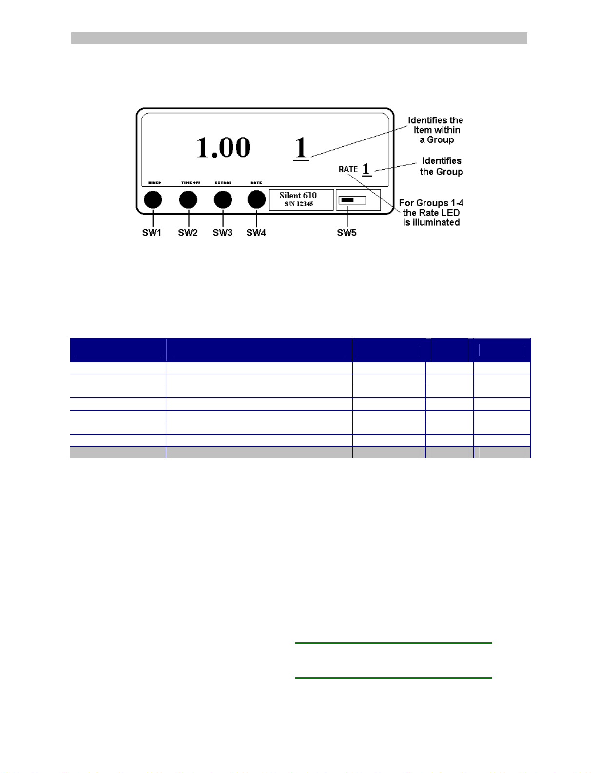
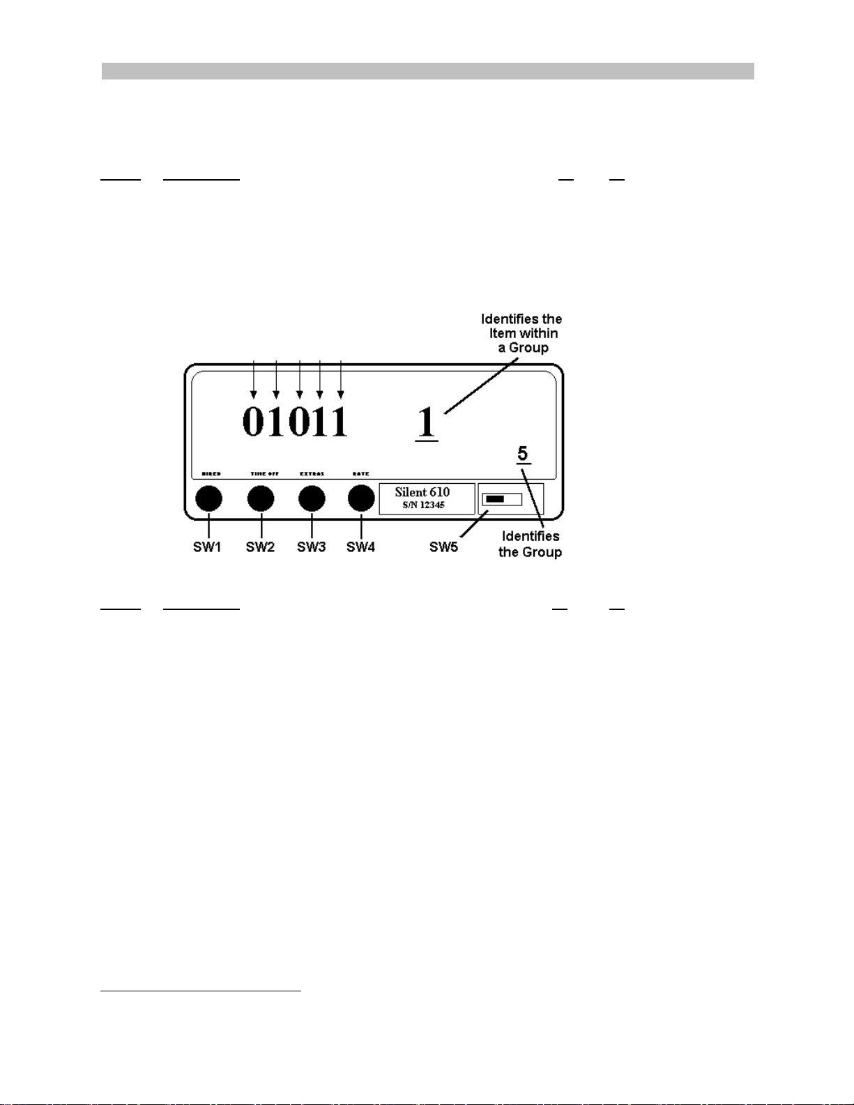
2. Press SW1 to step through the available Groups as listed above. The group number displays in the
Rate window, (above SW5).
3. Press SW2 to step through and select the available Items in each Group (see specific Group
instructions for available Items lists).
4. Press SW4 to confirm Item selection.
5. Press SW3 to change the value of the flashing character.
6. Press SW2 to move one character position to the left.
7. Repeat Steps 5 and 6 (SW3, SW2) until the correct value is displayed.
8. Press SW4 to save.
Group 0 Calibration
To properly calculate the fare, the taximeter
must be calibrated to the vehicle over a
measured mile (km). After the taximeter
has been installed, the following steps
should be performed:
1. Drive the vehicle to the beginning of a
measured mile (km).
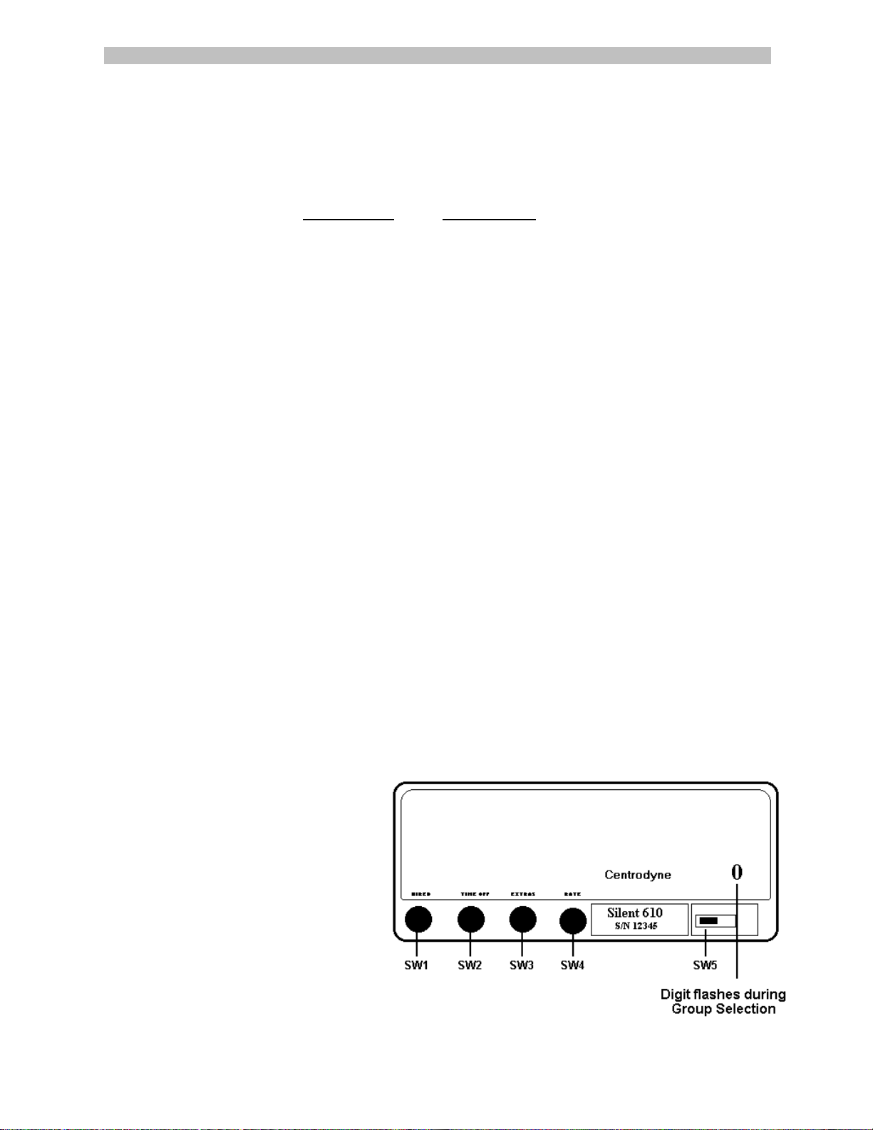
2. Slide SW5 to the left to enter
programming mode. “0” should display
in the Rate display (see drawing).
If not, see page 7, Group 9 Password Entry/Edit.
3. Press SW2 and the current meter calibration is displayed in the Fare window.
4. Press SW4 and the last number in the Fare display will flash.
If not, see page 8, Group 9 Password Entry/Edit.
1

5. Drive the vehicle over a measured mile (km) and the Fare display will show the speed signal
calibration as you drive. If the taximeter does not count the speed signal pulses, the meter is not
connected properly.
6. At the end of the mile (km), stop the vehicle, press SW4 to record the displayed calibration.
7. Slide SW5 to the right and test the meter over the mile (km) for proper Fare calculation.
If the vehicle calibration is known, the calibration number may be entered using the same push-button
sequence described in Groups 1-4 Rate Programming, page 2.
Note: The taximeter will not be as accurate if you use the vehicle odometer in place of a measured mile (km).
2

Switch Config: SW1 Select Group SW2 Select Item & Move Character left SW3 Change Character Value SW4 Enter SW5 Programming Switch
Groups 1-4 Rate Programming (and optional Rates 5-8)
When in Groups 1 to 4, the RATE legend is illuminated and flashes on and off. Taximeters with the optional 8
RATE feature will illuminate and flash the RATE legend when stepping through all 8 rates.
To program a Fare or Tariff:
1) Slide SW5 to the left to enter programming mode.
2) Press SW1 until RATE 1 is displayed on the meter.
3) Press SW2 to select the Item. The flag drop amount is displayed in the Fare window and Item "1" is
displayed in the Extras window.
Pressing SW2 steps through the list of Items in the Group.
The Item number, 1 through 8, is shown in the Extras window and the amount or value is shown in the Fare window.
Item Description Example Meter
Display Your Fare
1. Flag Drop Initial dollar charge $ 1.25 001.25
2. Drop Distance Fraction of mile (km) fare increments 1/10 mile (km) 00.100
3. Distance Rate Dollar amount charged per mile (km) $ 1.00 001.00
4. Time Rate Dollar amount charged per hour $12.00 012.00
5. Fare Increment Amount charged per fraction of mile (km) $ .10 000.10
6. Extra Increment Amount charged for extras $ .50 000.50
7. Maximum Extras Max charge allowed for extras $99.99 099.99
8. DO NOT USE DO NOT USE-LEAVE AT 000.00 000.00 000.00
To change (Item 1) Flag Drop:
4) Press SW4 (to confirm Item selection). The last number in the Fare window will flash (if the
number is not flashing, the meter has "Password" option, see page 9).
5) Press SW3 to change the value of the flashing digit.
6) Press SW2 to move to the next digit to the left (the number to the left will begin to flash).
7) Repeat this sequence (SW3 and SW2) until the Flag Drop you want is displayed.
8) Press SW4 to save.
To change Items 2 through 7:
Press SW2 to step through and select the Item number to edit. The Item number is displayed in the Extras
window and the amount or value of that Item is displayed in the Fare window. Continue using the same
sequence (steps 4 through 8) as above to change the rest of the Items for Rate 1. Use the same procedures
to program each of Rates 2, 3 ,4, (and optional rates 5, 6, 7 and 8).
1/10 = .100 1/7 = .143 1/4 = .250
1/9 = .111 1/6 = .167 1/3 = .333
1/8 = .125 1/5 = .200 1/2 = .500
The table contains a few examples of drop
distances in decimal value.
3

Switch Config: SW1 Select Group SW2 Select Item & Move Character left SW3 Change Character Value SW4 Enter SW5 Programming Switch
Group 5 Control Options
Control Options are factory set and, in most cases, do not require additional programming.
Program
Item 1 Description 1 0
A1Automatically print receipt upon going “Vacant” Yes No
B Sum fare and extras and display total in fare display Yes No
C1Print kilometers or miles on receipts and statistics Km Miles
D Allow statistics reset while in “Stats” display mode Yes No
E Prohibit rate change when in “Hired” state YES NO
Group 5 Control Options
Item 1: A B C D E
Item 2: F G H I J
Program
Item 2 Description 1 0
F Tax Method A or Tax Method B B A
(A=Tax included in rate) or (B=Tax calculated at end of trip)
G2Inhibit Extras at time of day (Extras are not permitted Yes No
between times programmed in Items 6 and 7 of Group 7
H Total Units (increments) or Fares (monies) Units Fares
I2Date format Day/Month or Month/Day DD/MM MM/DD
J2Clock format 12 or 24 hour 12hr 24hr
123
To change the Control Options factory settings:
1. Slide SW5 to the left to enter programming mode.
2. Press SW1 to select Group 5. The group number displays in the Rate window, (above SW5).
3. Press SW2 to step through and select Item 1 or 2.
4. Press SW4 to (to confirm Item selection). The last digit in the Fare window will flash.
5. Press SW3 to change the character value.
6. Press SW2 to move one character position to the left.
7. Repeat Steps 5 and 6 (SW3, SW2) until the correct value is displayed.
8. Press SW4 to save.
1For use with Printer option.
2Requires RTC option.
4
3Requires Auto Rate Change option.

Group 6 Specialty Options
Specialty Options are factory set and, in most cases, do not require additional programming.
ITEM
1 Tax Rate
Enter a tax value to 2 decimal places. For example: for 5% tax, enter 5.00
In tax method A, the tax amount adjusts the time and distance rates accordingly when
going “Hired”. For tax method B, the tax amount is added to the sum of the fare and
extras (if applicable) at the end of the trip.
DISABLE tax calculations: enter a value of 0.00 RANGE: 0.00 - 100.00
21Auto Rate Change At $ Amount
Enter a value in dollars and cents. When this value is reached in the fare display the
current rate will be incremented by 1 and the new rate will apply.
DISABLE auto rate change at $ amount: enter 0.00 RANGE: 0.00 - 655.35.
31Auto Rate Change At Distance Amount
Enter a distance value as a whole number greater than 0. While “Hired” and this distance
value is reached, the current rate will be incremented by 1 and the new rate will apply.
DISABLE auto rate change at distance amount: enter 0 RANGE: 0 - 65535.
4Critical Speed
Enter a speed value. If this speed is reached while in “Hired” state, the meter will stop
accumulating charges.
RANGE: 0 - 00255.
5 Reset Statistics
If programmed with zeros, the reset function will operate normally. If a value greater than
0 is programmed, then that value must be entered in order to reset the statistics.
RANGE: 00001 - 65535.
6 TIP INCREMENT
Enter the Tip increment value required. Each press of the programmed Tip Increment
switch will add this value to the total tip.
RANGE: 0.05 - 1.00.
To change the Specialty Options factory settings:
1) Slide SW5 to the left to enter programming mode.
2) Press SW1 to select Group 6. The group number displays in the Rate window, (above SW5).
3) Press SW2 to step through and select the Item (1 – 6).
4) Press SW4 to (to confirm Item selection). The last digit in the Fare window will flash.
5) Press SW3 to change the character value.
6) Press SW2 to move one character position to the left.
7) Repeat Steps 5 and 6 (SW3, SW2) until the correct value is displayed.
8) Press SW4 to save.
Repeat Steps 2 through 8 as required, until all Specialty Options are programmed.
Notes 1. Requires Auto Rate Change option.
2. For use with Printer option.
3. Requires Real Time Clock option.
5

Group 7 Clock/Calendar
To edit the time and date (Clock option):
1. Slide SW5 to the left.
2. Press SW1 until a “7” shows in the Rate window on the right.
3. Press SW2 to select item 1, 2 or 3.
4. Press SW4 and the last digit in the Fare window will flash.
5. Press SW3 to change the flashing digit to the correct value.
9) Press SW2 to move one character position to the left.
6. Continue using the same button sequence (SW3, SW2) until the correct value is displayed.
7. Press SW4 to record the value into memory.
Clock Calendar Items Description Format Range
1. Hours/Minutes Current time in hours and minutes HH/MM 00:00 – 23:50
2. Current Date
Month/Day
Or
Day/Month
MM/DD
or
DD/MM
01-01 – 12-31
or
01-01 – 31-12
3. Year/Day of Week
Current Year (last 2 digits of year)
and
Day of week, (1 – 7 {Sun = 1})
YY/DD 00-01 – 99-07
6

SW1 Select Group SW2 Select Item / Move Digit Left SW3 Select Character Position / Change Character Value SW4 Confirm / Save
Group 8 Printer Text
Eight text lines may be programmed for the customer receipt and statistics printouts. Items 1, 2, 3 and 4 are
printed at the top of the receipt while items 5, 6, 7 and 8 are printed as the last 4 lines of the receipt. For the
statistics printout only items 1 to 4 are printed at the top of the printout. Before you edit these text lines, first
see the ASCII table and text programming sheets on pages 4 & 5 for organizing the text lines to be printed.
Item or line "9" is the title for the statistics receipt (factory set as "TOTALS") and may be changed if required.
1. Slide SW5 to the left,
2. Press SW1 until Group "8" is displayed in the
Rate window on the right.
3. Press SW2 until the printer Line you want to
change, “1” through “8”, is displayed in the
Extras window.
4. Press SW3 to step through and select the 16
character positions in a printed line, shown on
the right side of the Fare window, after the
decimal point.
5. Press SW4 to confirm selection. The digit to the left of the decimal point will flash.
6. Referring to your duly completed Text Programming Sheet, press SW3 to change the value of the
flashing digit.
7. Press SW2 to move to the next digit (the digit to the left will now flash).
8. Press SW3 to change the value of the flashing digit.
9. Continue using the same button sequence (SW3, SW2) until the correct value is displayed.
10. Press SW4 to record the value into memory.
11. Press SW3 to select the next character position, (1 through 16) and use the same push button
sequence as above (SW4, SW3, SW2) to change the values.
12. Repeat this procedure (from Step 3) to enter all eight lines of printed text.
If a line is not required, ensure 000 is entered for the ASCII value for all 16 positions in the line.
FORMAT: CCC.LL. CCC is an ASCII decimal code for the required letter (refer to ASCII table) and LL is the
position in the line for the letter. There are 16 positions in a line.
RANGE OF CCC: 032.01 - 127.16, RANGE OF LL: 1 -16.
7

Printable Character Table For S620 Strings
ASCII Table
Char Dec Char Dec Char Dec
SPACE 32 B 66 d 100
! 33 C 67 e 101
" 34 D 68 f 102
# 35 E 69 g 103
$ 36 F 70 h 104
% 37 G 71 i 105
& 38 H 72 j 106
' 39 I 73 k 107
( 40 J 74 l 108
) 41 K 75 m 109
* 42 L 76 n 110
+ 43 M 77 o 111
, 44 N 78 p 112
- 45 0 79 q 113
. 46 P 80 r 114
/ 47 Q 81 s 115
0 48 R 82 t 116
1 49 S 83 u 117
2 50 T 84 v 118
3 51 U 85 w 119
4 52 V 86 x 120
5 53 W 87 y 121
6 54 X 88 z 122
7 55 Y 89 { 123
8 56 Z 90 | 124
9 57 [ 91 } 125
: 58 \ 92 ~ 126
; 59 ] 93 CR 13
< 60 ^ 94 LF 10
= 61 _ 95
> 62 ` 96
? 63 a 97
@ 64 b 98
A 65 c 99
* * * C A B
1 2 3 4 5 6 7
42
42
42
67
65
66
32
line
number
character position
character value
LINE 1
* * * C A B #
1 2 3 4 5 6 7 8
42 42 42 61 65 66 32 35
8

Silent 620 String Programming Sheet
CHARACTER POSITION
1 2 3 4 5 6 7 8 9 10 11 12 13 14 15 16
1
1 2 3 4 5 6 7 8 9 10 11 12 13 14 15 16
2
1 2 3 4 5 6 7 8 9 10 11 12 13 14 15 16
3
1 2 3 4 5 6 7 8 9 10 11 12 13 14 15 16
L
I
4
N
1 2 3 4 5 6 7 8 9 10 11 12 13 14 15 16
E
5
#
1 2 3 4 5 6 7 8 9 10 11 12 13 14 15 16
6
1 2 3 4 5 6 7 8 9 10 11 12 13 14 15 16
7
1 2 3 4 5 6 7 8 9 10 11 12 13 14 15 16
8
1 2 3 4 5 6 7 8 9 10 11 12 13 14 15 16
* Y E L L O W C A B L T D *
1 42 89 69 76 76 79 87 32 67 65 66 32 76 84 68 42
Character
Decimal
Sample of Line 1 Printer Tex
t
9

Group 9 Password Entry/Edit
When this option is enabled, no editing of data is allowed until the correct password is entered (however,
viewing the data is permitted).
Enter the password as follows:
1. Slide SW5 to the left, press SW1 until a "9" is shown in the Rate display on the right.
2. Press SW2 to display all 0's in the Fare display.
3. Press SW4 and the digit on the right in the Fare display will flash.
4. Press SW3 to change the flashing digit to the correct value.
5. Press SW2 to move one position to the left, (the digit starts flashing)
6. Continue using the same push button sequence (SW3, SW2) until the correct password is displayed.
7. Press SW4 to enter the password into memory.
If it is accepted, the taximeter exits GROUP 9 and goes to GROUP 0. The taximeter will not accept an
incorrect password.
To edit or enter a new password
1. Enter the current password as above.
2. Return to GROUP 9, and you may now enter a new password (don't forget it).
RANGE 00000 - 99999.
10

RESETTING STATISTICS
There are two different versions of the statistics reset function in use;
1 older style meter with a 32K EPROM and 2 newer meters with a 64K EPROM.
Newer Meters (64K) Old Style Meters (32K)
Taximeter Totals or Statistics:
The option to reset Meter Totals must be turned on and
off in programming mode. Password protection for
Meter Totals is not provided. To reset Meter Totals:
1. First perform steps # 1 to # 7 for older style meters
(right column).
2. Slide the program switch to the right to return to
taximeter operation.
3. To reset statistics, press the statistics button (extras
Button) once, then immediately press switch # 1
(hired button) and then switch # 4 (rate button). The
statistics have now been reset.
4. Remember to go back and disable the ability to reset
statistics performed in step # 1 above, if desired.
Daily Totals or Statistics:
Perform the following steps to reset the DAILY STATS:
1) ensure the meter is VACANT,
2) press the Time-Off button (SW2) to view the DAILY
STATS
3) immediately press the Hired button (SW1), followed
by the Rate button (SW4).
The DAILY STATS should now be reset, except if the
taximeter has been programmed with Password
protection (see step # 8 for old style meters to the
right). Perform the following to reset DAILY STATS if
the taximeter has Password protection;
1) after performing the above three steps, the Fare
window will display 00000 and the Extras window will
display 00. The Extras display is a counter showing
the number of times the DAILY STATS has been
reset. A five-digit password must now be entered
into the Fare window.
2) using the standard programming button sequence,
enter the five digit password to reset the DAILY
STATS.
Meter Totals or Statistics:
1. To enable the reset statistics feature, first slide the
programming switch to the left.
2. Press switch # 1 (hired button) until “ 5 “ is
displayed on far right of meter.
3. Press switch # 2 (time button) once. You should
have a “ 1 “ in the Extras display and 5 digits in the
Fare display, example “ 01001 ”.
4. The first zero from the right in the Fare display
(underlined above) needs to be changed. To do
this, press switch # 4 (rate button) once and the
first digit on the right will start to flash on and off.
5. Press switch # 2 and the second digit from the right
will flash on and off.
6. Press switch # 3 to change the digit to a “1“. A “1“
in this position enables statistics reset and a “0“
disables statistics reset.
7. Press switch # 4 to record changes (digit stops
flashing).
8. If you wish to protect the statistics reset with a
password, press switch # 1 until a “ 6 “ is shown on
the far right of the meter. Press switch # 2 until a “
5 “ is shown in the Extras display. Enter a 5-digit
password into the fare display using the normal
button procedure.
9. Slide the program switch to the right to return to
taximeter operation.
10. To reset statistics, press the statistics button
(extras Button) once, then immediately press switch
# 1 (hired button) and then switch # 4 (rate button).
Statistics should now be reset, unless a password
is required, in which case the fare display will
shown “ 00000 “. Enter correct password to reset
statistics.
11. Remember to go back and disable the ability to
reset statistics performed in step # 1 above, if
desired.
11

SILENT 610/620/150 INSTALLATION
Black wire, CB 1 - Connect to black wire of Centrodyne transducer. For electronic vehicle speed sensors,
connect this wire to vehicle ground (-).(Notes:1 & 2)
White wire, CB 1 - Connect to white wire of Centrodyne transducer. For electronic vehicle speed sensors,
connect this wire to the speed signal output of the sensor.(Notes:1 & 2)
Black wire, CB 2 - Connect to vehicle ground (-).
Red wire, CB 2 - Connect using a 2 amp (SILENT 610) or 4 amp (SILENT 620) in-line fuse to +12 volts at
the fuse box or directly to the positive (+) post at the battery.
Green or White wire, CB 2 - SEE NOTE IN DIAGRAM BELOW. If relay option employed, connect to post 85
using a ½ amp fuse to allow meter to drive dome/top light relay. Connect post 86 to ground, post 30 via
switch and fuse to +12 volts battery, post 87A to dome or top lights, and post 87 to cheater lights if required.
ENSURE LOCATION OF METER DOES NOT INTERFERE WITH AIR BAG DEPLOYMENT
Note 1. Ensure the taximeter internal speed signal jumper has been selected properly, i.e., select electronic for vehicle
speed sensors (usually magnetic) that provide an analog or varying amplitude signal (low amplitude), and select
mechanical for Centrodyne transducers or sensors that provide a digital, on/off, high/low type signal. See page
13 for Speed Signal Jumper Selection.
Note 2. When using a Centrodyne transducer (part # Y014-1) connect ground and signal wires as per above, and
connect the red or pink wire to vehicle +12 volts (meter does not supply transducer power).
NOTE: 10/1/96 Dome Relay
Wire changed to White Wire.
Therefore, if Green Wire
present use for Dome Relay, i
f
White Wire Only use for Dome
Relay
12

SILENT 610/620
SPEED SIGNAL JUMPER SELECTION
Speed signals will generally be of two types, 1) digital or 2) analog.
1. Digital speed signals provide an on/off, high/low signal. Mechanical transducers on speedo cables
usually provide a digital signal, and in general, speed signals provided by the vehicle computer (ECM) are
also digital (Example – Caprice and most GM Vehicles).
2. Analog speed signals vary in amplitude and frequency at different speeds. Analog speed signals are
usually provided by a magnetic speed sensor in the transmission (Example - Crown Victoria and most
Ford Vehicles).
To change the speed signal jumper:
1) Remove the front sealing screw and the two screws on the back of the taximeter.
2) Slide the front face and printed circuit boards out of the case.
3) Locate the corner of the board where the jumpers are located and carefully remove the jumpers
and re-install as illustrated below.
JP2
For digital speed signal input, (square wave) place
j
umpers so that the pins in position A & B and A & B
are connected.
For analog speed signals, (magnetic pick-up) place
j
umpers so that the pins in position B & C and B & C
are connected.
13

THE "SILENT 610/620/150"* TAXIMETER & PRINTER
OPERATING INSTRUCTIONS
Operation of the taximeter is controlled by the 4 push buttons on the face of the unit.
HIRED
When the taximeter is off or
“VACANT”, you may hire the meter
by pressing the HIRED button once.
The meter will display the initial or
drop charge in the fare display and
the word HIRED will be displayed.
When the taximeter is HIRED the
meter will automatically be in TIME
ON.
Some versions of meter require the
driver to enter the number of
passengers in the car prior to going
HIRED. To do this:
Press the HIRED (SW1) button.
A blinking “1” appears in the FARE
window.
Press SW3 to increment the
number of passengers.
Press SW4 to accept the number in
the FARE window as the number of
passengers. The meter goes into
HIRED mode.
If no buttons are pressed for a
period of 10 seconds (may vary by
meter configuration) the meter will
automatically switch to HIRED
mode, saving the current value in
the FARE window as the number of
passengers.
While in the HIRED state it will not be
possible to change to any other state
except HIRED TIME OFF.
HIRED - TIME OFF
After the taximeter has been HIRED
you may place the meter in TIME
OFF by pressing the TIME OFF
button once. The meter will now
display TIME OFF. Time charges
will not be accumulated in this state.
To resume accumulating time
charges, press the TIME OFF button
once.
While in the HIRED TIME-OFF state
it is only possible to change to
HIRED Time On or VACANT states.
EXTRAS
If EXTRAS are programmed into
your meter, ensure the meter is
HIRED Time On and press the
EXTRAS button once. The extras
amount will appear in the EXTRAS
display. Continue to press the
EXTRAS button to add to the amount
currently displayed (the extras
increment is pre-programmed).
While in the HIRED Time On state it
is only possible to change to HIRED
TIME OFF.
SUMMING FARE AND EXTRAS
To add the FARE and EXTRAS
amount, ensure the meter is HIRED
TIME OFF, and press the EXTRAS
button once. The meter will now
display the total of the Fare and
Extras in the Fare display, for five
seconds.
VACANT
To place the meter in VACANT or off
state, ensure the meter is HIRED
TIME OFF, and press the HIRED
button once. The meter will display
the word VACANT.
RATE
If more than one rate is programmed
into the taximeter (maximum of 4),
you may change RATES when the
meter is VACANT. To change rates,
ensure meter is VACANT, and press
the RATE button to select Rates 1
through 4.
16-Rate Meter
Some meter versions may have
more than 10 rates. If this is the case
then rates greater than 9 are
displayed as follows:
In VACANT mode the tens digit is
displayed in the rightmost digit of the
EXTRAS window, while the ones
digit is displayed in the RATE
window.
In HIRED mode the tens digit is not
displayed in the EXTRAS window.
Only the ones digit of the rate is
displayed in the rate window. To
differentiate between rates 1-9 and
10-19 the ones digit is blinking for
rates greater than 9. So a 2 in the
RATE window indicates rate 2 while
a blinking 2 in the RATE window
indicates rate 12.
STATISTICS DISPLAY
The STATISTICS or TOTALS may
be viewed when the meter is
VACANT. Press the EXTRAS button
in succession to display the following
on the taximeter:
ITEM DESCRIPTION
1 Total Fares
2 Total Extras
3 Total Tax
(if applicable)
4 Total Miles (km)
5 Total Paid Miles (km)
6 Number of Trips
7 Calibration
11Time of Day
21Date
31Year - Day of Week
Note 1: Requires RTC (real time clock)
factory option and these item numbers
flash to identify clock/calendar.
STATISTICS RECEIPT
To print a statistics receipt, ensure
the meter is VACANT, press the
EXTRAS button once to enter
statistics, and then press the TIME
OFF button to print the receipt.
FARE RECEIPT
The customer fare receipt is printed
from the VACANT state, except
when meter is programmed for
DAILY STATISTICS (see page 13
DAILY DRIVER STATS) . At the
end of the trip, after the meter has
been placed in VACANT, press the
TIME OFF button once to print the
fare receipt. The total fare will be
displayed on the meter.
PAPER FEED
Paper should be loaded into the
meter when VACANT. See next
page for instructions.
14

SILENT 620 PRINTING METER PAPER ROLL INSTALLATION
To replace the paper roll in the “Silent 620” High Speed Printing Meter,
1. First open the hinged paper door on top of the taximeter and remove the old paper core (and any
unused paper).
2. As illustrated above, ensuring the paper has a straight edge and the shiny/glossy side is facing
down, extend an inch or two of paper into the case towards the print mechanism.
3. Gently feed the paper under the black roller. The printer will automatically detect the paper and
feed it through the print mechanism.
4. The paper may also be fed manually through the printer. Press down on the roller release bar and
gently push the paper under the black roller and through the print mechanism (the auto paper feed
will also activate). When the paper is fed out the top of the printer, close the roller release bar.
5. Feed the paper through the slot in the hinged door, and close and latch the door.
SILENT 150 REMOTE PRINTER PAPER ROLL AND RIBBON INSTALLATION
To replace the paper roll in the “Silent 150” Remote Printer,
1) First open the hinged paper door on top of the printer and remove the old paper core
(and any unused paper).
2) As illustrated above, feed the paper under and through the paper guide.
The printer will automatically detect the paper and feed it through the print mechanism.
3) The paper feed button located on top of the printer may also be used to assist in loading paper.
4) Close the hinged door allowing the paper to extend out the top.
To replace the ribbon,
1) First remove the paper roll.
2) Where indicated on the ribbon, press down to eject and remove the ribbon.
3) Insert the replacement ribbon into the printer in the same direction as the one removed, ensuring the
exposed portion of the ribbon is behind the silver metal edge of the printer, and gently press down
on both sides of the ribbon.
15

CREDIT CARD OPERATION & RECEIPTS
WITHOUT WIRELESS COMMUNICATIONS
1) Follow normal taximeter operation until end of trip (do not go VACANT).
2) When you arrive at destination, place taximeter in TIME-OFF (switch # 2).
3) Place the passengers credit card into the top of the card reader, with the
magnetic bar facing towards the taximeter, and swipe the card
downwards in a continuous motion.
4) The taximeter will begin to print the receipt automatically. The taximeter
will print the first half of the receipt and then pause for approximately 10
seconds. This allows you to tear off the first receipt before the taximeter
prints the second half. Alternatively, you may press switch # 2 anytime
after the first receipt has printed to begin printing the second receipt.
5) The driver may now write the approval number on the blank line provided
on the second receipt.
6) Pass both receipts to the passenger. Passenger fills in tip amount and
total on both receipts and signs the second receipt. Passenger returns
both copies of receipt to driver.
7) Driver should verify totals and passenger signature with signature on
credit card.
8) Driver retains the signed receipt and returns credit card and first half of
receipt to passenger.
9) To return taximeter to VACANT, press switch # 1.
10) If the taximeter runs out of paper when printing the receipts, press switch
# 1 to return taximeter to VACANT and load in another paper roll. The
taximeter will print another set of receipts, when the taximeter is
VACANT, by swiping the credit card again. As soon as the first receipt
has printed, you must press switch # 2 to obtain the second receipt.
YELLOW CAB
CAB # 1234
12/01/95 09:00
12/01/95 09:12
TRIP # 31
DIST 4.20 mi
FARE $ 2.40
EXTRAS $ 1.00
SUB TOT $ 3.40
TIP______________
TOTAL___________
Paid By:
VISA
1234567890123456
YELLOW CAB
CAB # 1234
12/01/95 09:00
12/01/95 09:12
TRIP # 31
DIST 4.20 mi
FARE $ 2.40
EXTRAS $ 1.00
SUB TOT $ 3.40
TIP_______________
TOTAL____________
Paid By:
VISA
1234567890123456
EXPY. DATE 95/10
Approval:
__________________
Signature:
__________________
THANK YOU
(123) 456-7890
16
This manual suits for next models
1
Table of contents
Other Centrodyne Measuring Instrument manuals
Popular Measuring Instrument manuals by other brands

KEPCO
KEPCO KEPtrol F/C quick start guide

enertexbayern
enertexbayern Enertex KNX Smartmeter 85A (RT) Manual and Configuration

IKALOGIC
IKALOGIC SP259 Series Datasheet and User Manual

red lion
red lion APOLLO manual

B+K precision
B+K precision 308A instruction manual

Tinker & Rasor
Tinker & Rasor SR-2 Product instructions