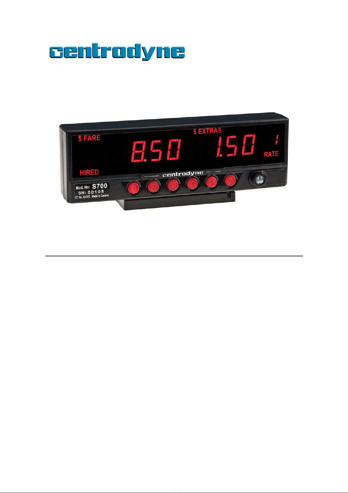
S700 Taximeter Operating & Programming Guide
4
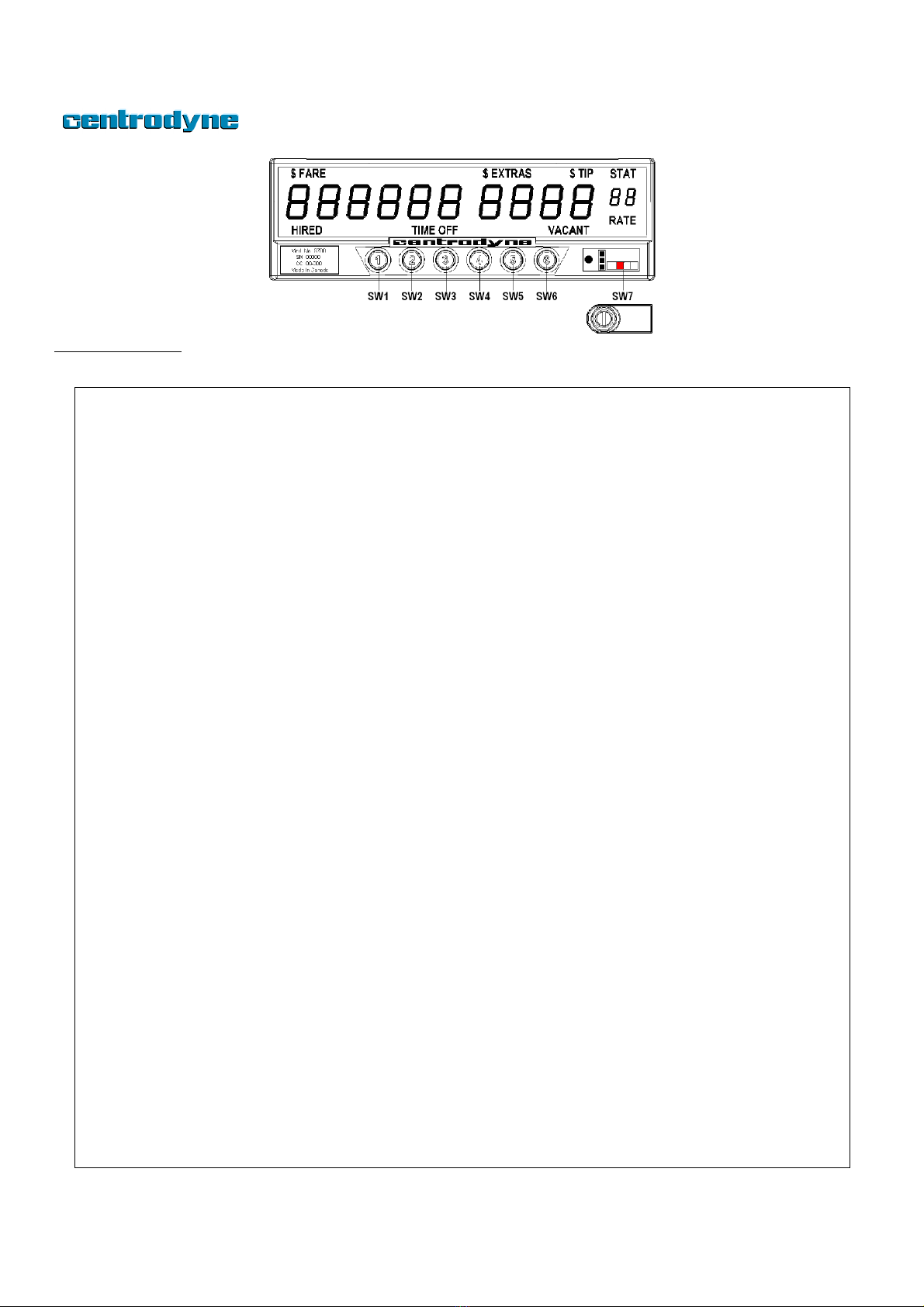
S700 Operation
Operation of the taximeter is controlled by the 6 switches (SW1 to SW6) on the face of the taximeter.
When the taximeter is off or “VACANT”, you
may Hire the meter by pressing switch SW1
once. The meter will display the initial or drop
charge in the fare display and the word
HIRED will be displayed. When the taximeter
is HIRED the meter will automatically be in
TIME ON.
While in the HIRED state it will not be
possible to change to any other state except
HIRED TIME OFF.
HIRED - TIME OFF
After the taximeter has been HIRED you may
place the meter in TIME OFF by pressing
switch SW2 once. The meter will now display
TIME OFF. Time charges will not be
accumulated in this state.
To resume accumulating time charges, press
the SW 2 once.
While in the HIRED TIME-OFF state it is only
possible to change to HIRED Time On or
VACANT states.
EXTRAS
If EXTRAS are programmed into your meter,
ensure the meter is HIRED Time On and
press SW4 to add Extras. The extras amount
will appear in the EXTRAS display. Continue
to press SW4 to add or increment Extras.
You may press SW3 to subtract or
decrement the Extras amount currently
displayed.
While in the HIRED Time On state it is only
possible to change to HIRED TIME OFF.
To add the FARE and EXTRAS amount,
ensure the meter is HIRED TIME OFF, and
press SW4 once. The meter will now display
the total of the Fare and Extras in the Fare
display, for five seconds.
VACANT
To place the meter in VACANT or off state,
ensure the meter is HIRED TIME OFF, and
press SW1 once. The meter will display the
word VACANT.
RATE
If more than one rate is programmed into the
taximeter (maximum of 16), you may change
RATES when the meter is VACANT. To
change rates, ensure meter is VACANT, and
press SW6 to select Rates 1 through 16.
STATISTICS DISPLAY
The STATISTICS or TOTALS may be viewed
when the meter is VACANT by pressing SW3
once. The Fare display shows the amount
and the Extras display shows the item
number. View statistics by pressing SW4 to
go to the next item or SW3 to the previous
item. Press SW6 to switch between Total
Statistics and Daily Statistics. The letter “d” is
displayed in the Rate window when
displaying Daily Statistics.
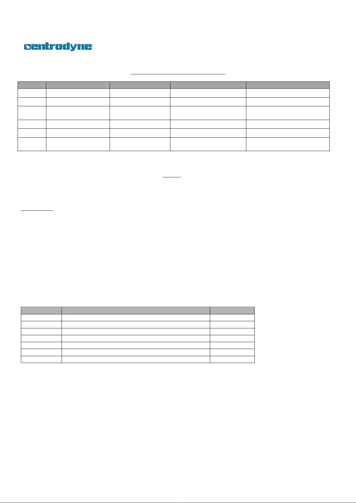
ITEM DESCRIPTION
1 Total Fares
2 Total Units
3 Total Extras
4 Total Taxes
5 Total Miles (km)
6 Total Paid Miles (km)
7 Total Number of Trips
To print a statistics or totals receipt, ensure
the meter is VACANT. Press SW3 once to
enter statistics (if desired, press SW6 to
switch to Daily Statistics) and then press
SW5 to print the receipt.
FARE RECEIPT
The customer fare receipt may be printed at
the end of the trip when the meter is Hired
Time-Off or after the meter has been placed
VACANT, by pressing SW5 once. One
duplicate may also be printed by pressing
SW5 again.