Centrodyne S700 User manual

S700 Quick Installation Guide
The S700 taximeter should be installed using the S700 Installation Drawing (below) as a guideline (see Legal Notice and
Disclaimer below). After installation of the S700 has been completed, meter calibration and rate programming need to be
performed. Typically, the rates are pre-programmed at the factory prior to shipping. All meters when first installed should be
calibrated over a measured mile.
NOTE: All S700 taximeters are equipped with Electronic Sealing of the Installation (ESI).
ESI requires the meter to be electronically matched to the vehicle bracket. This feature
prevents the meter from going HIRED when the meter and bracket are not matched. A
blinking HIRED legend indicates that the meter and bracket are not matched.
** Once your meter has been wired into the vehicle, perform the following steps, in order, to get up and running fast.
Switches and Displays on the S700
Step 1: Entering Program Mode
1. If not already done, remove the seal plate from the front right side of the meter by unscrewing the seal screw completely.
Put the plate and screw somewhere safe so as not to lose them.
2. Using a pen or small screwdriver, move SW7 (Red programming slide switch) to the left position. Either a 0or a 6will be
blinking in the RATE window (Small right-most display on the meter). If a 0 is blinking, proceed to Step 3. If a 6is
blinking, proceed to Step 2.
Step 2: Entering The Passowrd
1. If a 6 is blinking in the RATE window, then your meter programming is protected by a password. If you purchased your
meter directly from Centrodyne your password should be printed on your invoice. If you purchased from an authorized
dealer you will have to contact them for the password.
2. Press SW6 and 000000 is displayed in the FARE window.
3. Press SW6again and the right-most 0will begin to blink.
4. Press SW4repeatedly to change the blinking digit to the value you want.
5. Once you are satisfied with the value of the blinking digit, use SW2to select the next digit to the left for editing.
6. Repeat 4. and 5. above until the correct password is displayed in the FARE window. Press SW6to enter the password.
If you have entered the correct password, the meter will display a blinking 0in the RATE window. This indicates that the
meter is now unlocked for programming. Go to Step 3.

S700 Quick Installation Guide
Step 3: Calibration
1. Drive the vehicle to the beginning of a measured mile (km).
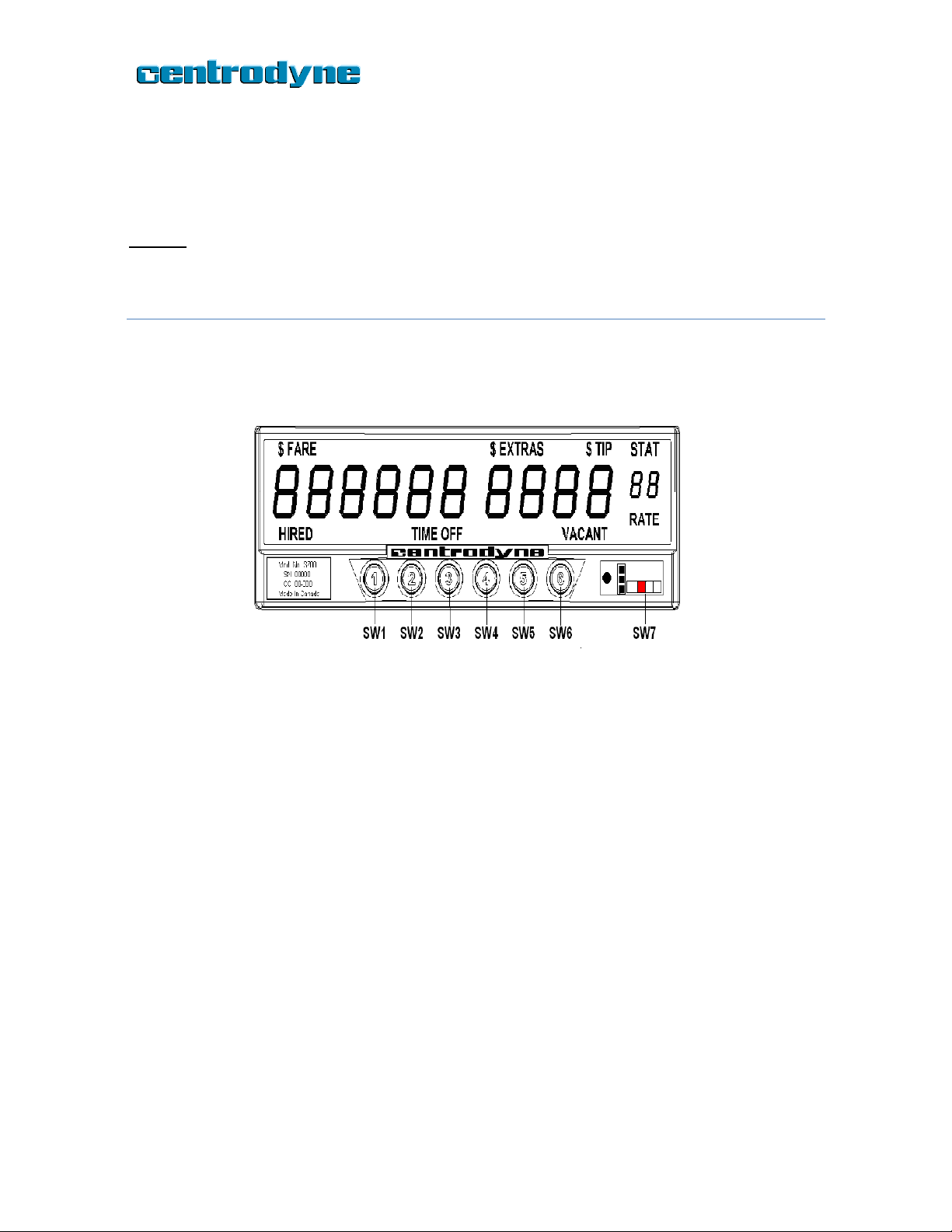
2. SW7 must be in the left position. A blinking 0should be displayed in the RATE window. If you see a blinking 6in the
RATE window, then go back to Step 2 above and complete it before continuing. Once you see a blinking 0in the RATE
window, proceed to 3. below.
3. Press SW6.The 0in the RATE window should stop blinking and the current meter calibration value is displayed in the
FARE window.
4. Press SW6again and the right-most digit in the FARE window will start to blink.
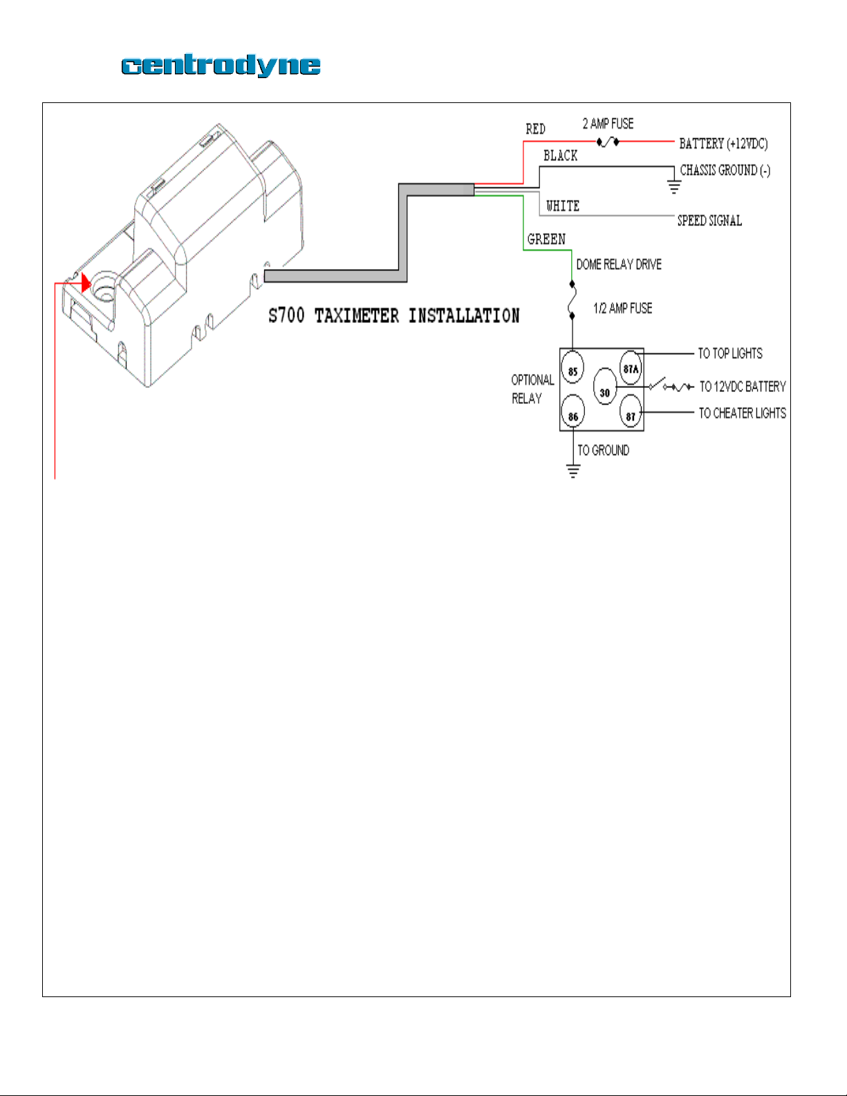
5. Drive the vehicle over a measured mile (km). While driving, the FARE window will show the speed-pulse count as you
progress. If the FARE window continues to show zero as you drive, this indicates that the meter is not connected
properly.
6. At the end of the mile (km), stop the vehicle and wait for about 5 seconds. Press SW6to record the displayed
calibration.
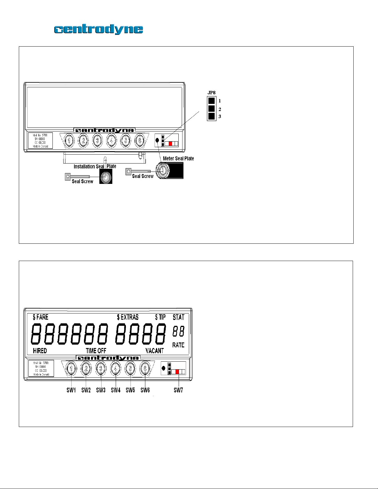
7. Slide the red programming switch, SW7, back to the right.
8. Test the meter over the mile (km) for proper Fare calculation.
** THE TAXIMETER WILL NOT BE AS ACCURATE IF YOU USE THE VEHICLE ODOMETER IN PLACE OF A MEASURED MILE (KM).
Step 4: Programming Rate 1
1. SW7 must be in the left position. A blinking 0should be displayed in the RATE window. If you see a blinking 6in the
RATE window, then go back to Step 2 above and complete it before continuing. Once you see a blinking 0in the RATE
window, proceed to 2. below.
2. Keep pressing SW4 until there is a blinking 1in the rate window, AND the “RATE” legend is blinking.
3. Press SW6. The “RATE” legend should be illuminated solid and there should be a blinking 1in the RATE window.
4. Press SW6 again and the blinking 1 in the RATE window should be on solid. There will be a 1 displayed in the EXTRAS
window and the Flag Drop value will be displayed in the FARE window. You are now editing Rate 1.
5. At this point the number in the EXTRAS window indicates the rate item you are programming and the number in the
FARE window indicates the value of that item. When you first enter rate 1, a 1will be displayed in the Extras window
(Item 1 is the Flag Drop) and the value of the Flag Drop will be displayed in the Fare window. The table below shows
the list of 8 items that make up a rate.
6. Press SW4to cycle through the list of Items. The Item number, 1 through 8, is shown in the Extras display and the
amount or value is shown in the Fare display.
To edit or change the Flag Drop: (Or any other item)
7. Press SW4until 1(or the desired item number) is shown in EXTRAS display.
8. Press SW6to select that item for editing. You can tell the item was selected as the right-most digit in the
FARE display will blink.
9. Press SW4 to change the blinking digit until you reach the desired value.
10. Press SW2to move one digit to the left. That digit will begin to blink.
11. Repeat 9. and 10. above until the desired Flag Drop is displayed in the Fare window.
Item
Description
Example
Meter
Display
Your
Fare
1. Flag Drop
Initial dollar charge
$ 1.25
001.25
2. Drop Distance
Fraction of mile (km) fare increments
1/10 mi(km)
00.100
3. Distance Rate
Dollar amount charged per mile(km)
$ 1.00
001.00
4. Time Rate
Dollar amount charged per hour
$12.00
012.00
5. Fare Increment
Amount charged per fraction of
mile(km)
$ .10
000.10
6. Extra Increment
Amount charged for extras
$ .50
000.50
7. Maximum Extras
Max charge allowed for extras
$99.99
099.99
8. Tax Rate
Percentage tax rate
10.0%
010.00
TYPICAL DROP DISTANCES IN DECIMAL VALUE
1/10 = .100
1/7 = .143
1/4 = .250
1/9 = .111
1/6 = .167
1/3 = .333
1/8 = .125
1/5 = .200
1/2 = .500

S700 Quick Installation Guide
12. Press SW6to accept the value and the Flag Drop will be entered into the meter.
13. Press SW4to move to the next item. The item number is displayed in the EXTRAS window. (Item 2 is Drop
Distance in decimal value)
14. Repeat 8. through 12 above to edit all eight items for Rate 1.
15. Slide the red programming switch to the right to accept the Rate programming.
Step 5: Programming Rate 2
1. SW7 must be in the left position. A blinking 0should be displayed in the RATE window. If you see a blinking 6in the
RATE window, then go back to Step 2 above and complete it before continuing. Once you see a blinking 0in the RATE
window, proceed to 2. below.
2. Keep pressing SW4 until there is a blinking 1in the rate window, AND the “RATE” legend is blinking.
3. Press SW6. The “RATE” legend should be illuminated solid and there should be a blinking 1in the RATE window.
4. Press SW4. There should now be a blinking 2in the RATE window. (If you want to edit another rate keep pressing SW4
until the blinking number in the RATE window matches the Rate you want to edit)
5. Press SW6 again and the blinking 2 in the RATE window should be on solid. There will be a 1 displayed in the EXTRAS
window and the Flag Drop value will be displayed in the FARE window. You are now editing Rate 2.
6. You can now use the same procedure outlined in Step 4 above, (sub-steps 5 through 15) to complete the programming
for Rate 2.
Step 6: Wrapping up and Testing the meter
1. SW7 should be in the right position. The FARE and EXTRAS windows should be blank. The RATE legend should be on
solid and a 1 should be displayed in the RATE window. The VACANT legend should be on solid.
2. Replace the seal plate onto the meter and secure with the seal screw. Do not over-tighten as you may crack the plastic.
3. Place the Installation seal plate into position as indicated in the Figure 2 below. Secure with a seal screw. Do not over-
tighten as you may crack the plastic.
4. Your meter is now ready to use.

S700 Quick Installation Guide
(800)655-5575 or (800)679-9939
Legal Notice and Disclaimer
Dear Customer:
Due to variations in use, governing regulations, and other variables, Centrodyne does not provide instructions regarding installation of the meter. The purchaser
and/or user assume sole responsibility for installing the meter in a safe manner and in compliance with regulations governing its use and operation. Centrodyne
provides no warranty, expressed or implied, regarding the accuracy, adequacy, completeness, legality, or reliability of any calibration or installation of the meter.
Centrodyne provides no warranty, expressed or implied, regarding compliance with any regulation governing the use and operation of the meter.
Centrodyne further disclaims any liability and damages (including without limitation any consequential, special, incidental, punitive, or exemplary damages) arising
out of the calibration, installation, or use of the meter. In no event will Centrodyne be liable for any claim arising out of the calibration, installation, or use of the meter,
whether in contract, tort (including negligence and product liability), or under any other theory of liability.
If any part of this disclaimer is determined to be void, invalid, unenforceable, or illegal, including but not limited to the disclaimers and liability limitations set forth
above, then the invalid or unenforceable provision will be deemed superseded by a valid, enforceable provision that most closely matches the intent of the original
provision, and the remainder shall remain in full force and effect.

S700 Quick Installation Guide
S700 Taximeter Installation Drawing
Mounting Bracket: Provision has been made for two screws that may be used to secure the
bracket to the mounting surface.
Red Wire = Power: Connect using a 2 amp in-line fuse directly to the +12 volts DC power
source.
Black Wire = Ground: Connect to chassis ground (-).
White Wire = Speed Signal: Connect to the speed signal source. Ensure the taximeter’s
speed signal jumper behind the seal plate is set properly (see separate instructions).
Green Wire = Relay (Dome): If not used, tape off and isolate. If relay option employed,
connect Green wire to post 85 using a ½amp fuse to allow meter to drive the dome/top
light relay. Connect post 86 to ground, post 30 via switch and fuse to +12 volts, post 87A to
dome or top lights, and post 87 to cheater lights if required.
CAUTION: Always check with the vehicle manufacturer before making any
electrical connections to the Taximeter. Follow the manufacturer directions
to ensure a reliable and safe installation.
Figure 1

S700 Quick Installation Guide
Speed Signal Jumper
Selection
2) To set speed sensor input to
digital (on/off, square wave),
place jumper so that Pin 1
and 2 are connected.
B) To set speed sensor input to
analog (magnetic, varying amplitude
levels), place jumper so that Pin 2
and 3 are connected.
Sealing
2. Secure meter to bracket with
installation seal plate and
screw.
2. Secure access to programming
with meter seal plate and screw.
Figure 2
Operating Instructions - Basic Trip
VACANT: The taximeter is normally in the
Vacant state. If required, press switch 6 to
select rate. Press switch 1 (SW1) to Hire
taximeter.
HIRED: When Hired the drop or initial charge is
displayed in the Fare window. Press switch 4
(SW4) to add Extras, and switch 3 (SW3) to
subtract Extras.
TIME OFF: At the end of the trip, press switch 2
(SW2) to go Hired – Time Off. If Extras have
been entered, you may press switch 4 (SW4) to
add the Extras to the Fare amount for a period
of 5 seconds. To end the trip, press switch 1
(SW1) and the meter will return to Vacant.
Figure 3
(800)655-5575 or (800)679-9939
Other manuals for S700
2
Table of contents
Other Centrodyne Measuring Instrument manuals
Popular Measuring Instrument manuals by other brands

RCbenchmark
RCbenchmark 1580 Series Assembly manual

Contrec
Contrec 515 Operation manual

Rohde & Schwarz
Rohde & Schwarz R&S RT-ZPR20 user manual

PCB Piezotronics
PCB Piezotronics 010M144/006 Installation and operating manual

Siko
Siko IMS360 quick start guide

Endress+Hauser
Endress+Hauser LT5 operating instructions