8Tehničke upute REGULACIJA Cm Pelet-set
Maintenance, Cleaning
1.0. MAINTENANCE
1.1. CLEANING THE BURNER
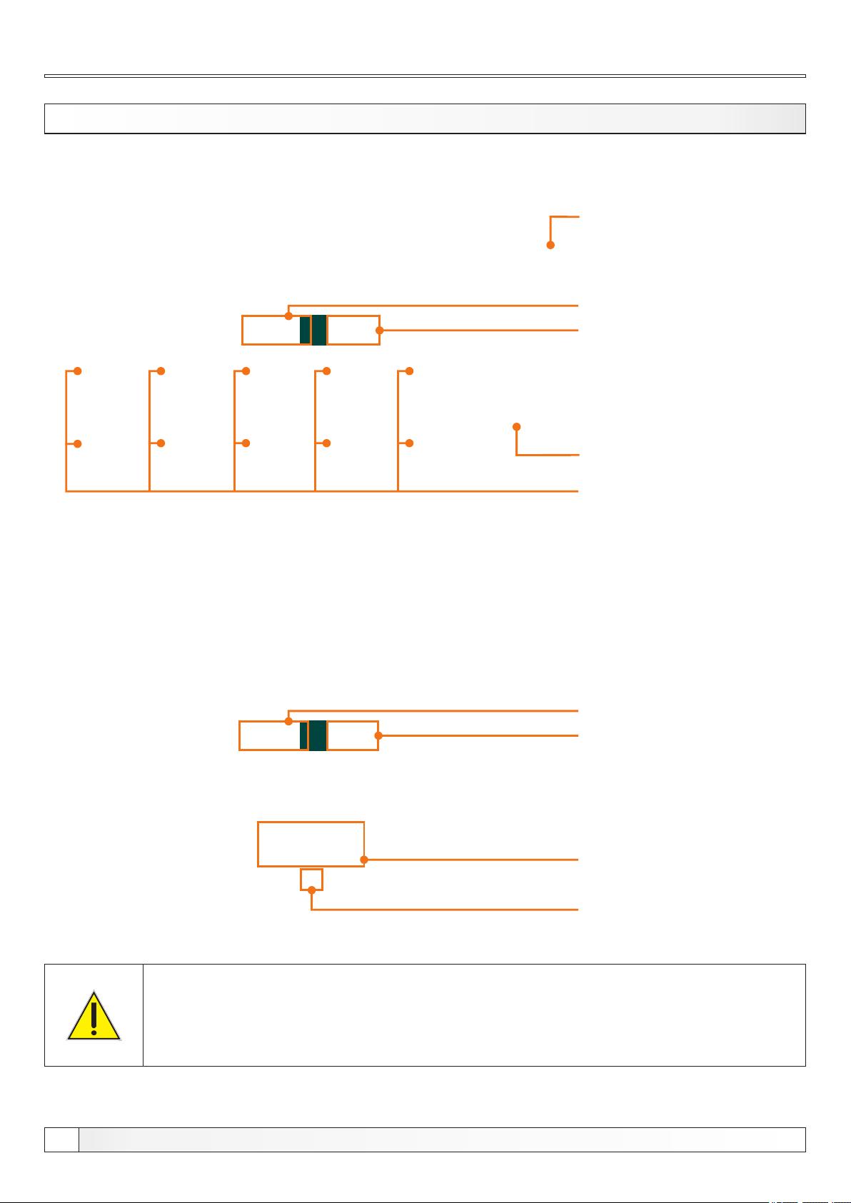
Under "CLEANING" menu are two options:
Cleaning: this option is used to start the burner fan on the set RPMs to
clean the burner grate (note: depending of the pellets quality grate will
be more or less clean. After this procedure, burner grate should be
removed and cleaned and the burner head should also be cleaned.)
Burner fan: this option sets the burner fan RPMs during cleaning
Technical instructions REGULATION Cm Pelet-set
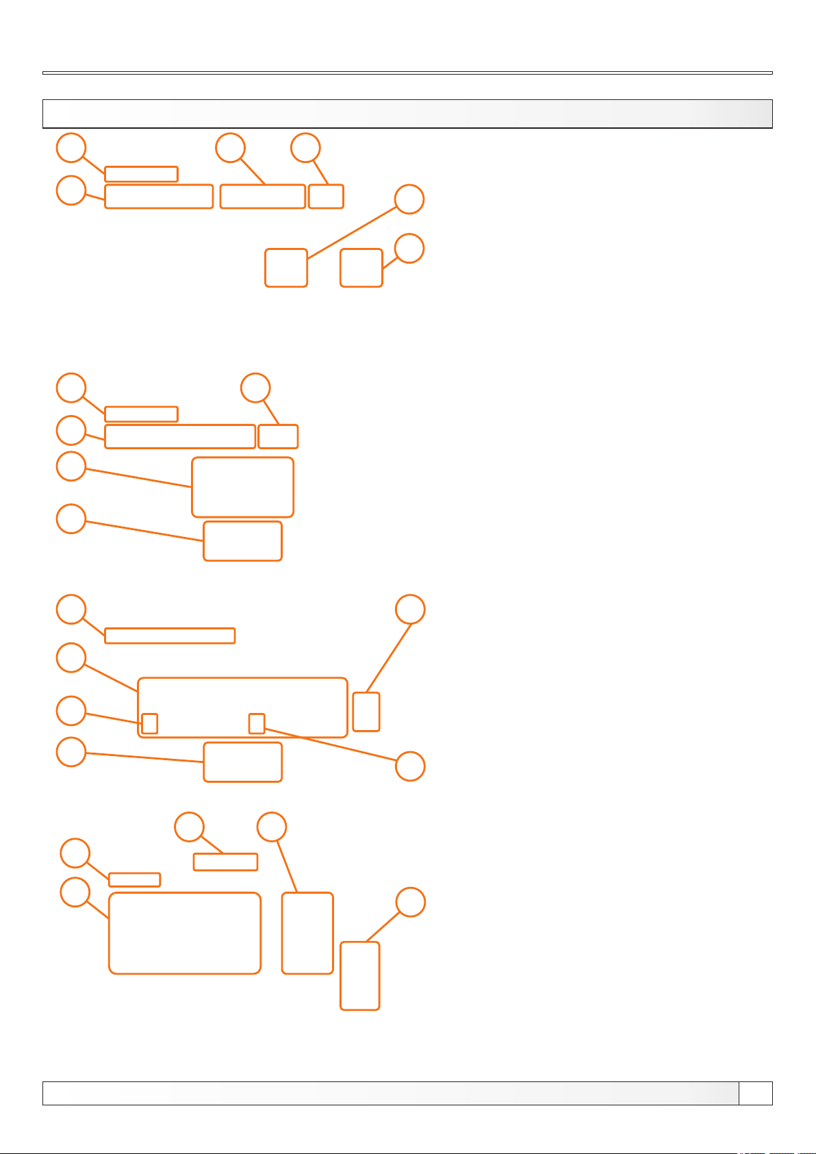
1.1.1. CLEANING
Press the "START" button to start the burner fan for 10 min.
After pressing the "START" button countdown is started for 10 min,
after which burner fan stops automaticaly
Press "AIR VALVE" button to open the electro-magnetic valve and to
clean the burner with compressed air.
After pressing the "AIR VALVE" countdown ist started for 60 sec in
which time "AIR VALVE" button is disabled to alow compressor to fill its
tank.
This option is used to adjust burner fan RPMs during cleaning
procedure
Possible adjustment:
- Factory adjustment: 3000 rpm
- Minimal adjustment value: 500 rpm
- Maximal adjustment value: 3000 rpm
1.1.2. BURNER FAN
NOTE: burner cleaning option is not replacing the need for manual
cleaning of the burner and burner grate. It should be manually cleaned
regulary according to the technical manual.