1 - Boiler temperature
2a - Working hours counter
2b - Working hours counter with
reset option
3 - Cyclone
4 - Pneumat (air cleaning)
5 - Flue gas temperatures
6 - Lambda probe
7 - Secondary air 1 fan
8 - Secondary air 2 fan
9 - Firebox pressure
10 - Photocell
11 - Conveyor 1 temperature
12 - Movable grate
13 - Primary air fan
14 - Primary air fan lid
15 - Conveyor 1
16 - Conveyor 2
17 - Conveyor 3
18 - Outdoor temperature
19 - Backfire protection lid
20 - This area depend about configuration
21 - Errors and warnings
22 - Choosen fuel
23 - Name of saved settings image
24a - Bunch with a blue angular arrow (The firebox flap
is raised to the height when the first microswitch is
pressed, the boiler conveyors (screw feeder) work
in a special mode).
24b - Bunch with a red angular arrow (The firebox flap
is raised to the height when the first and second
microswitches are pressed, the error "E119 -
FUEL TOO HIGH" is announced and the automatic
electrical fuses "DI" and "F2" eject in the el. boiler
cabinet. Conveyors (screw feeder) do not work.
25 - Compressor with showned status (off / on)
(if is installed - additional equipment)
26 - Network status (CM-GSM/WiFi) / Profibus
(if is installed - additional equipment)
27 - Alternative boiler status (if it exist)
28 - Ash transport - TP-3M/9M/3000L-Multi Plus
340-580 (only for Multi Plus 340/450/580)
(if is installed - additional equipment)
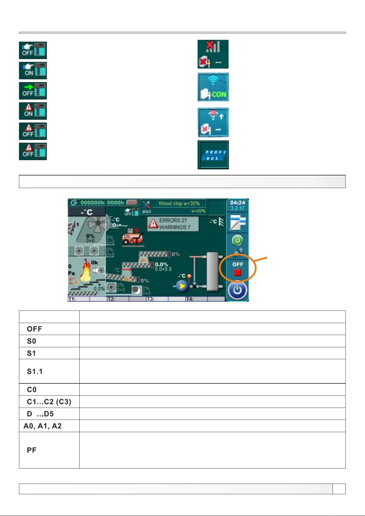
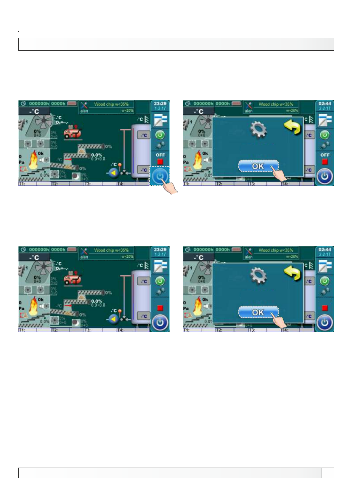
MAIN SCREEN
1
3
4
9
12
13 14
11
10
15
16
17
7
8
6
5
18
20
21
23 22
2a
25
2b
27
26
Main screen
24
28
Technical instructions REGULATION EKO-CKS Multi Plus 7
19