Centrometal CSK-Touch User manual
TU-CSK-T-09-2019-v1_16-ENG
CSK-Touch
Technical instructions
for installation, use and maintenance
CSK-Touch digital room corrector
READY
www.centrometal.hr
e-mail: [email protected]
Centrometal d.o.o. Glavna 12, 40306 Macinec, Croatia
central tel: +385 40 372 600, fax: +385 40 372 611
service tel: +385 40 372 622, fax: +385 40 372 621
Company Centrometal d.o.o. assumes no responsibility for possible inaccuracies in this book
originated typographical errors or rewriting, all the pictures and diagrams are principal and it is
necessary to adjust each actual situation on the field, in any case the company reserves the right to
enter their own products such modifications as considered necessary.
TEHNIKA GRIJANJA
HEATING TECHNIQUE
Centrometal d.o.o. - Glavna 12, 40306 Macinec, Croatia, tel: +385 40 372 600, fax: +385 40 372 611
READY

Introduction, content
INTRODUCTION
CONTENT
TECHNICAL CHARACTERISTICS
DELIVERY CONTENT AND NECESSARILY ADDITIONAL EQUIPMENT
INSTALLATION CSK-Touch DIGITAL CORRECTOR
FIRST TURNING ON
MAIN DISPLAY
BOILER MENU
MENU
SCHEDULE
TEMPERATURE
SETTINGS
INTRODUCTION
Digital room corrector CSK-Touch, with a 4.3'' color touch screen, provides room temperature control
and turning on / off of the heating circuit. In addition to measuring and correcting room temperature,
this room corrector allows you to adjust the temperature of the Accumulation tank or Hydraulic
crossover as well as to adjust the DHW temperature, if any, and to set Schedules of the heating circuit,
DHW and boiler. By connecting multiple digital room correctors to the boiler, it is possible via one
corrector to adjust the desired temperature at other correctors. The digital room corrector connects
to the PelTec boiler with a built-in CM-WiFi box and CM2K module wirelessly via wifi signal.
With compact and elegant design, it fits perfectly into any space in your home.
Thank you for purchasing the product of Centrometal d.o.o.
Please read these technical manuals carefully so that you can use and adjust this control unit as easily
as possible. Once you have read the manuals, place them in an appropriate place where you can
easily find them if you need further information on the operation and use of control unit. Please make
sure that the contol unit is discontinued after the end of use to reduce the pollution of the environment.
CONTENT
2
2
3
3
4
5
6
7
8
8
9
11
Technical instructions CSK-Touch
2
Notes
Technical instructions CSK-Touch 15
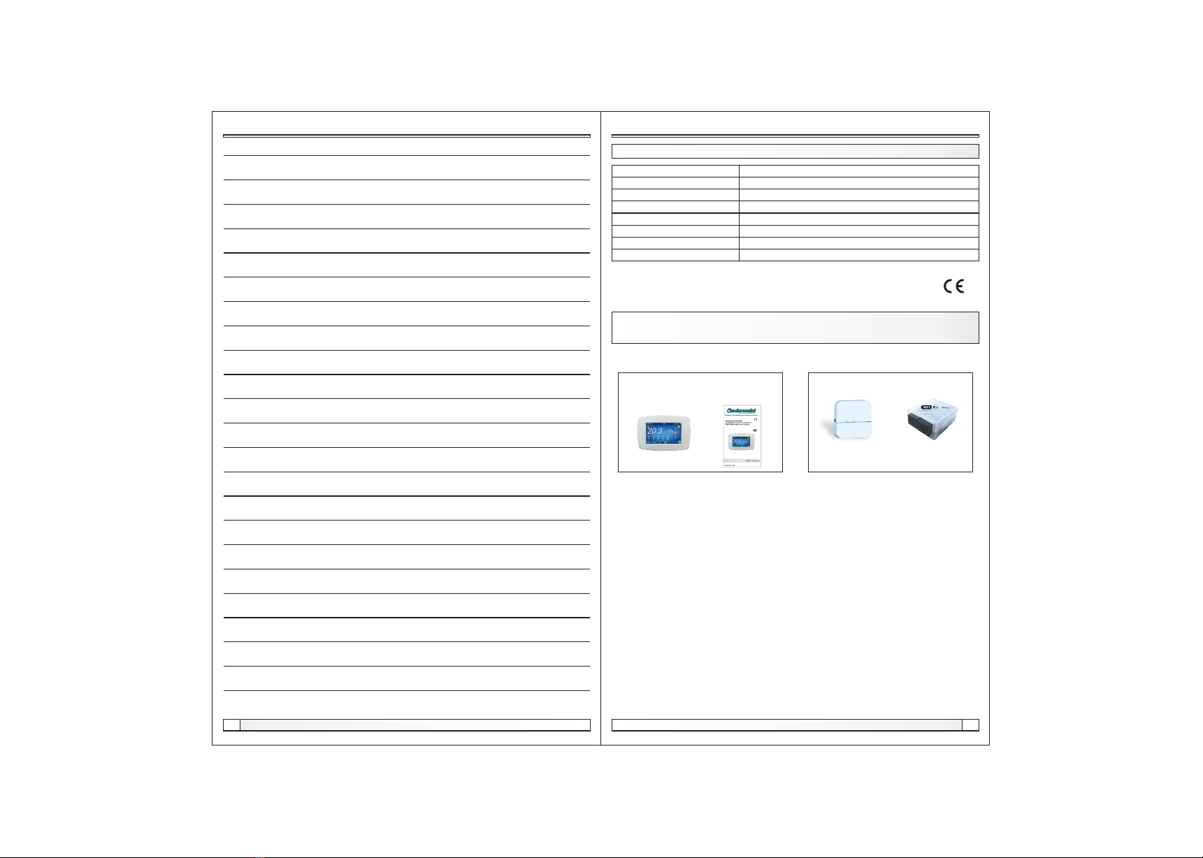
TECHNICAL CHARACTERISTICS OF CSK-TOUCH
Power supply
Connection with boiler/CM2K
Temperature range
Display type
Consumption
Dimensions (WxHxD)
CSK-Touch mass
Case material
30VAC
Wirelles: WiFi (CM-WiFi box)
from -40°C to +70°C
4.3" TFT, resistive touch screen
max. 1.5W
150x100x24 mm
225 g
ABS
EC Declaration
The product complies with the requirements of the current rules and is marked EC.
The EC Declaration of Conformity is available on request, contact the manufacturer.
DELIVERY in cardboard box:
CSK-Touch Technical
instructions
Note:
CM2K and CM-WiFi box are not in the content
of the delivery
Modul CM2K CM-WiFi box
Necessarily additional equipment
DELIVERY CONTENT AND NECESSARILY ADDITIONAL
EQUIPMENT
Notes
Technical instructions CSK-Touch
14
Technical characteristics, delivery content and necessarily additional equipment
Technical instructions CSK-Touch 3
Installation
CSK-TOUCH DIGITAL CORRECTOR INSTALLATION CONNECTING TO
THE BOILER / CM2K MODULE THROUGH CM-WIFI BOX
Technical instructions CSK-Touch
4
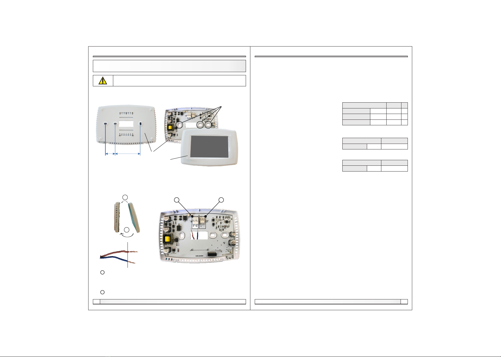
At a height of about 130-160cm from the floor, never directly above the heat source or near the
window. At the installation site, drill 2 holes at a distance according to the bottom sketch, diameter fi
6mm, depth 35-40mm. Insert dowels into the drilled holes.
24 mm 60 mm
places to
attach to the
wall
Be sure to turn off the power supply at the place of installation of the corrector!
Ensure an unobstructed wifi signal from the corrector to the CM-WiFi box!
base
Push the power wire through the hole at the base of the corrector and insert the wires into the power
connector (locations F and N, left connector). Before inserting the wire, press the terminal block
connector, insert the wire all the way down, and release the terminal block connector. Do the same
for the other wire. Attach the connector base to the wall with screws. Attach the screen to the upper
brackets and gently press the screen to the bottom of the corrector base. When the corrector is
properly installed, the current up to the corrector can be turned on.
a Power connectors.
It is necessary to remove the insulating part of the wire and insert the conductor
part into the connectors.
F - Phase
N - Zero
b A connector for wired connecting the module CM2K (currently unused)
insulating part conductive part
a
F N
b
screen
1.
2.
Settings
3.7. Shutdown
The Digital Room Concealer is intended for year-round use, ie room temperature measurement. If
you want to turn off the corrector completely (because it will not be used or want to save electricity
when we do not intend to use corrector), pressing the OK button will completely off the corrector.
When you want to restart the room corrector, you need to press the screen for a few seconds until a
beep sounds and the corrector lights up and starts working on the last view before shutting down.
3.5.2. Sound type
Select one of ten sound types offered when you
press the screen or an error / warning occurs
3.5. Sound
3.5.1. Sound volume
Adjusting one of three preset volume levels
or muting completely when a button is displayed on the
screen and when an error / warning occurs.
3.6. Info
Information on the version of the software entered in the corrector..
3.8. Load factory
Load the factory settings of the room corrector. After that, the room concealer must be
reconfigured.
3.4.4. Screensaver
After a certain screen idle time, the screen saver is turned on to reduce power consumption and
extend the screen life. The screen saver works in two levels: after Time 1, the backlight intensity
decreases, and after Time 2 has elapsed, the measured room temperature of the selected view and
the current clock will change on the screen. By tapping the screen, the screen saver turns off.
3.4.4.1. Backlight
The backlight intensity after Time 1 has elapsed, ie when the screen saver turns on.
3.4.4.2. Time 1
Time that starts to run after the last touch on the
screen (after which the screen saver is turned on).
3.4.4.3. Time 2
Time that begins to flow after Time 1 has passed
(in Time 2 the Backlight intensity decreases and after
that time, only the current room temperature / current clock starts to appear on the screen
Backlight 20
Factory: min./max.
5 / 50
uni.
Time 1 60 10 / 600 sec
%
Time 2 10 0 / 720 min
Sound volume 3
Factory: setting
OFF / 1/2/3
Sound type Type 6
Factory: setting
Type 1...Tip 10
Technical instructions CSK-Touch 13
Settings
3.2. Views
In the Views menu, you can define the number of views or correctors that can be monitored on this
digital corrector and define the name of each view and assign it a heating circuit that it controls. On
the main screen, depending on the number of views selected, the letters of the view appear in the
menu bar (from A to H, user-assigned names are only visible on the selected screen, not in the
menu bar). If there are more than 2 views, the other views are selected by pressing the "..." menu
(three dots) followed by the other selected views. After clicking on one of the desired views, the
menu bar returns to the possible selection of the first 2 views.
3.3. Measurement corr.
If the measured temperature on the digital corrector
deviates from the actual room temperature, in this menu the measured temperature on the digital
corrector screen can be corrected.
3.4. Display
Menu for changing the settings of the digital corrector screen.
3.4.2. Backlight
The intensity of the backlight when the corrector is in normal operation or when the settings are
changed.
3.4.3. Weather forecast
If the CM-WiFi box is connected to the Internet, there is below the measured room temperature a
weather forecast for the place where the CM-WiFi box with the currently read temperature from the
server (with the date and hour of reading the current temperature and forecast) and the weather
forecast for today appears and for the next four days (with a minimum and maximum daily
temperature). If the CM WiFi box is not connected to the Internet, the current forecast will not be
displayed on the screen. Then it is recommended to turn off the weather forecast and it will not
longer be displayed on the screen.
Background 1
Factory: min./max.
1 / 6
Backlight 100 30 / 100 %
Measurement corr. 0
Factory: min./max.
-5.0 / 5.0 °C
3.2.1. No. of views
Selects the number of views or associated room correctors that can be controlled via this digital
corrector. If only this digital corrector exists, the
number 1 must be selected
Heating circuit 0
Factory: min./max.
0 / 255
Weather forecast ON
Factory: setting
OFF / ON
3.2.x. View A/B/C/D/E/F/G/H
3.2.x.1. View Name
Each view can have a name according to the user's wishes (eg Living Room, Ground floor ...).
3.2.x.2. Heating circuit
Each view must be assigned a heating circuit wich is controled by this view (usually each corrector
controls its own heating circuit).
3.4.1. Background
Selects the background image of the screen that will
be displayed in the normal operation of the corrector.
menu bar
No. of views 1
Factory: min./max.
1 / 8
Technical instructions CSK-Touch
12
FIRST TURNING ON
First turning on
Before turn on the corrector for the first time, it is necessary to configure the heating circuit on the
boiler / CM2K module to which the corrector will be connected. On the boiler control in the
Regulator menu, in the selected heating circuit, in the Corrector menu, it is necessary to select
Digital corrector, and in the menu Addr. dig. corrector, select the desired corrector address (the
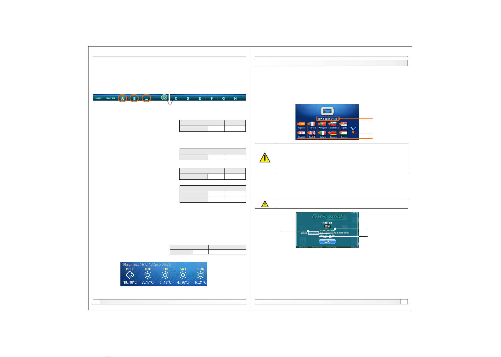
same must be selected on the corrector later ) .After starting the corrector for the first time, a menu
will appear on the first screen to select the desired corrector language. The desired language of the
corrector doesn't have to be the same as the language of the boiler. To select the desired language
for the corrector, press the flag of the desired language on the screen.
Corrector software
version
Language selection
Page scroll
The screen must not be pressed (with your finger ...) when connecting the the room
corrector to the el. power supply. If the screen of the corrector is pressed on arrival
the el. power supply (the screen shows 'Firmware update'), the corrector enters the
software insertion mode which can only be used by authorized serviceman. If the
screen is accidentally pressed, it is necessary to turn off the power on the corrector
and turn it on again without ever pressing the screen to get the corrector ready for
operation.
After selecting the language on the first screen the indicator flashes that the corrector is not
connected to the boiler. The corrector is adjusted in the menu Menu -> Settings. The menu 3.1.1.
Connection type selects how the corrector will be connected to the boiler / CM2K module. If the
corrector is connected via the CM-WiFi box (currently the only option), the correct WiFi ID from the
menu Info on the boiler control must be entered in the corrector menu 3.1.2. WiFi ID.
If a specific corrector address is selected on the boiler control unit (if there is more than one digital
corrector, selection of the address of each individual corrector is obligatory), the same address
should be selected on the corrector in the menu 3.1.3. Corrector address.
The corrector can be connected to the boiler / CM2K either directly via the CM-WiFI box or through
another digital corrector. If you want to connect the corrector directly to the boiler / CM2K, in the
menu 3.1.4. Destination address you need to select a WiFi box, and if you want to connect the
corrector to the boiler / CM2K via another corrector (in case the corrector cannot receive the CM-
WiFi box signal ), in the menu 3.1.4. Destination address it is necessary to select the address of
another corrector to be connected.
The CSK-Touch room corrector can be connected to a CM-WiFi box with software
version v.1.11 or later and a Peltec / -L boiler with software version v.2.86 or later.
WiFi ID Boiler sofware version
Software vesrion of
CM-WiFi box
Technical instructions CSK-Touch 5
Technical instructions CSK-Touch
6
First turning on, main display
1
2
5
6
7
8
9
10
12 13 14 15 16
3
CSK-Touch is connected
with a boiler
CSK-Touch is not connected
with a boiler
11
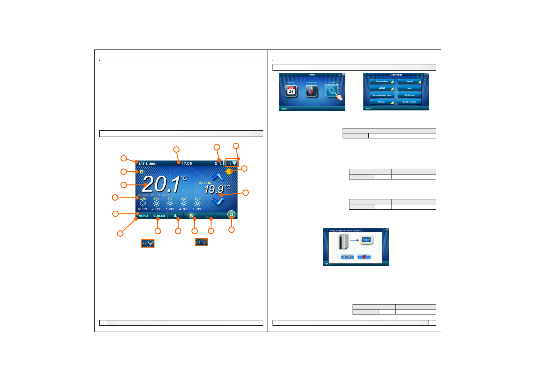
Depending on the view selected (heating circuit), the current measured room temperature can be
displayed on the screen, you can set the desired room temperature (correction of the set
temperature on the boiler control) or switch off the heating circuit and see the weather forecast for
several days in advance (if the boiler is connected to the Internet via the CM-WiFi box).
1. Date
2. Hour
3. Outside temperature
(if there is an outdoor temp. sensor)
4. WiFi signal / data transfer
5. Name of heating view / circuit
6. Room temperature (depending on the selected
view and the heating circuit, measured either on
the current room corrector or other corrector.
7. Day / night heating mode
8. Desired / set room temperature
9. Weather forecast (internet connection required)
10. Menu
11. Menu bar
12. Boiler menu - data from boiler control
13. A - overview of the selected heating circuit
14. B - overview of the selected heating circuit
15. Button for other views if set
16. Turn OFF / turn ON of the selected heating circuit
In the menu 3.2. Views it is necessary to assign each view of the corrector to a specific heating
circuit and add a name to it as desired. If there is only one room corrector in the heating system,
number 1 is selected in the menu 3.2.1Number of views. If there are more room correctors (digital
or analog) to be monitored on this corrector, the number of all correctors to be monitored should be
selected in this menu. Depending on the number of views selected, the same number of buttons for
editing the views (eg 3 views, View A, View B and View C buttons) appear in the menu 3.2 Views.
In the menu 3.2.2. View A you can change the name of that view (factory A) to eg Floor 1 or Zone 1
or Circle 1 or Living Room ... (max. 30 characters) and a heating circuit must be selected to be
joined by this corrector, 3.2.2.2. Heating circuit.
After the corrector connects to the boiler / CM2K (WiFi signal strength is white), it is necessary to
download the data from the boiler control by pressing the START button in the menu 3.1.5. Get data
After adjusting these parameters, the corrector is ready for use..
MAIN DISPLAY
4
3. SETTINGS
Settings
3.1. Connection
3.1.1. Connection type
Choose how to connect the room corrector to the boiler / CM2K. Currently enabled: Only connect
via WiFi Tree.
3.1.2. WiFi ID
It is mandatory to enter the WiFi ID (unique number of the CM-WiFi box) - the number is displayed
on the boiler control in the Information menu after connecting the CM WiFi box to the boiler.
3.1.3. Corrector address
The address selected on the boiler control must be the same as the one selected here. If there is
one digital corrector the address does not have to be defined (but it can), if there is more than one
digital corrector the address of each must be defined and the address of each digital corrector must
be different.
3.1.4. Destination address
One digital corrector must always be connected directly to the WiFi box (WiFi box destination
address selected). If we have more than one digital corrector, other correctors can be connected to
each other (eg when the signal from the WiFi box is too weak or missing) by selecting the
destination address of the nearest neighboring digital corrector (destination address ADR1 / 2 ...).
3.1.5. Get data
After configuring the room corrector or afterwards changing the language, it is necessary to
download the configuration / error / setpoint data from the boiler controller in order to print the
correct information on the digital corrector.
3.1.6. Language selection
When connecting a digital corrector for the first time, the digital corrector asks you to choose a
language that will display information on the screen. After selecting the language for the first time,
the language selection menu automatically shuts off. If you wish to change the language of the
corrector later, you need to activate the language selection in the menu 3.1.6. Language selection,
turn off the corrector 3.7. Shutdown and the language selection will appear on restart (long press
on the screen). After selecting a new language, it is necessary to retrieve the data from the boiler
control unit 3.1.5. Get data.
Corrector address Not defined
Factory: setting
Not defined / ADR 1/2/3/4/5/6/7/8
Language selection ON
Factory: setting
OFF / ON
Connection type WIFI BOX Tree
Factory: setting
WIFI BOX Tree / Wired / Home router
Destination address WIFI BOX
Factory: setting
WIFI BOX / >>>ADR 1/2/3/4/5/6/7/8
Technical instructions CSK-Touch 11
Technical instructions CSK-Touch
10
Temperature
2.x. DHW
2.x.1 DHW temp.
The default temperature of the
DHW tank.
DHW temp. 50
Factory: min./max.
40 / 80 °C
2.x.2 Differential of DHW
The default differential for starting the DHW
tank to warm up (Tdhw-dTdhw).
2.x. Buffer tank
2.x.1. Buffer tank temp.
Default buffer tank temperature (measured on the upper sensor).
2.x.2. Min buf. tank temp.
Default minimum buffer tank temperature (measured on the upper sensor) - when reached, the
heating pumps behind the storage tank are switched off.
2.x.3. Diff. buf. tank temp.
Default differential to start warming up the buffer
tank (measured on the upper sensor)
(Tbuff-dTbuff).
2.x.4. Diff. stop buff. tank
Default differential to turn OFF warming up the
AKU. tank (measured on the lower sensor)
(Tbuff-dTbuff off).
Buffer tank temp. 80
Factory: min./max.
40 / 85 °C
Min buf. tank temp. 20 5 / 66 °C
Diff. buf. tank temp 10 5 / 30 °C
Dif. stop buff. tank 5 3 / 30 °C
2.x.1. Crossover temp.
Hydraulic crossover temperature setpoint. Crossover temp. 80
Factory: min./max.
75 / 85 °C
Differential of DHW 5
Factory: min./max.
4 / 40 °C
2.1.4. Heating curve
Adjustment of the coefficient (slope) of the heating curve of the selected heating circuit
(dependence of the flow temperature on the outside temperature). Depending on the type of
heating installed and the thermal insulation of the building, the slope of the heating curve must be
adjusted - it is usually recommended for radiator heating curves from 1.0 to 4.0 and for underfloor
heating from 0.1 to 0.9.
2.1.5. Correction coeff.
Determination of the coefficient of influence of the room corrector on the flow temperature. The
higher this coefficient, the room corrector will have a greater influence on the calculated required
flow temperature of the selected heating circuit.
2.1.2. Day room temp.
Selects the default daily room temperature.
2.1.3. Night room temp.
Selects the default night room temperature.
Day room temp. 20
Factory: min./max.
5 / 30 °C
Night room temp. 20 5 / 30 °C
Heating curve 1.0 0,1 / 4.0
Correction coeff 1.0 0.1 / 5.0
Technical instructions CSK-Touch 7
BOILER MENU
Boiler menu
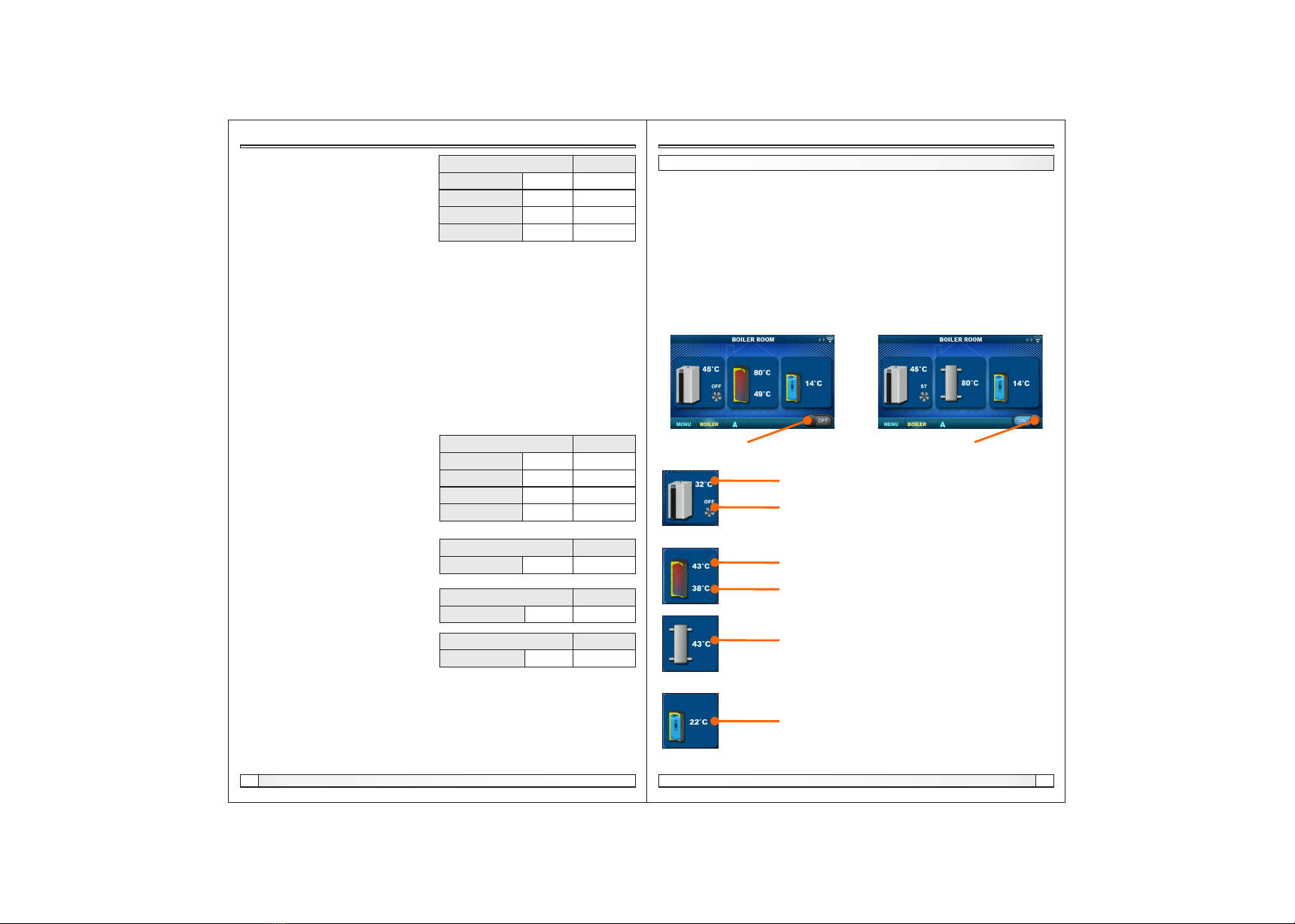
In the Boiler menu it is possible to monitor the operation of the boiler and the temperature of the
existing configuration, start and stop the boiler and check all faults / warnings that have occurred on
the boiler control. The display shows the current phase of operation of the boiler with the symbols of
flame and fan operation as well as the boiler temperature and, depending on the existing
configuration, the current temperature in the accumulation tank or hydraulic crossover and DHW
tank (if any). By pressing the ON / OFF button, the boiler can be switched on / off.
If a warning or an error occurs on the boiler control, a warning / error message is also displayed on
the corrector screen. Pressing the OK button on the error / warning screen of the corrector will
reduce the error / warning and remain recorded through the (Boiler) menu and the error / warning
menu can be read again.
Boiler ON/OFF
(position when boiler is switched off)
Boiler ON/OFF
(position when boiler is on)
Boiler + Buffer tank + DHW Boiler + Crossover + DHW
Boiler temperature
Boiler operating phase / has / no flame / boiler fan operation
Buffer tank temperature (up)
If an buffer tank is selected in the boiler configuration
Buffer tank temperature (down)
If an buffer tank is selected in the boiler configuration
If the DHW tank does not exist in the boiler control system,
the DHW tank image will not be displayed
Crossover temperature
If a hydraulic crossover is selected in the boiler configuration
Configuration:

Technical instructions CSK-Touch
8Technical instructions CSK-Touch 9
Menu, schedule Schedule, temperature
MENU
In this menu it is possible to set time schedule of all selected boiler heating and DHW circuits (if
any), adjust the temperatures of the selected heating circuits as well as any temperatures that can
be adjusted on the boiler control and adjust the room corrector settings.
1. SCHEDULE
In this menu it is possible to set the time schedule for each selected view (heating circuit), boiler
and, if any, heating of the DHW tank. The time schedule can be switched off or selected from one of
the tables with set time intervals of active and inactive function. Views and settings of existing time
schedules vary depending on the configuration.
1.X. Boiler
1.x.x. Schedule
Choose when the boiler is active or not active
on a particular day of the week - time schedules can be switched off or select one of 3 tables
where boiler activity times can be set. Only one table can be active at a time.
Schedule OFF
Factory: setting
OFF / Table 1/2/3
1.x.x. Table 1/2/3
Table for selecting the time when the boiler is active and when not. Green at the left edge of the
table indicates the start of time from when the boiler is active for heating, and red at the edge of the
Table indicates the start of time when the boiler is not active for heating. On each day of the week it
is possible to select 3 times the active state of the boiler and 3 times the time when the boiler is not
active for heating. The factory settings of the tables are: every day from Monday to Sunday from
06:00 hours the boiler is active for heating until 22:00 from when the boiler starts to be inactive until
the next day at 06:00. On the right side of the screen there are buttons to copy the desired day and
paste it to another selected day (copy / paste).
1.1. View A
1. 1. 1. Day/Night Temp.
Selecting the set room temperature mode -
Day temperature, Night temperature or Table selection.If the temperature mode is selected
according to the Table, the times in the following Tables must be set (switching the temperature
mode according to the specified time in each day). Only one Table can be active at the same time.
Day/Night Temp. Day/Night Temp.
Factory: setting
Day / Night / Table 1/2
1.1.x. Table 1/2
Time table for day / night room temperatures. Green at the left edge of the table indicates the start of
daytime temperature, red at the edge of the table indicates the start of nighttime temperature. It is
possible to choose 3 times daily and 3 times night temperatures on any day of the week. The factory
settings of the tables are: Every day from Monday to Sunday at 06:00 hours the daily temperature
of the room starts and lasts until 22:00 when the night temperature begins, which lasts until the next
day at 06:00. On the right side of the screen there are buttons to copy the desired day and paste it to
another selected day (copy / paste).
Depending on the configuration selected on the boiler, certain menus appear in the menu
2.Temperature in which the set temperatures and differentiations (seen on the boiler control) can
be changed:
Day / Night Temp. / Daily room temp. / Night room temp. / Heating curve / Correction coeff. / Buffer
tank temp. / Min. buf. tank temp. / Diff. buf. tank temp. / Diff. stop buff. tank / Crossover temp. / DHW
temp. / Differential of DHW
2.1.1. Day/Night Temp.
Day Temperature: maintaining a set daily temperature all the time
Night temperature: maintaining a set night temperature all the time
Table 1/2: Maintain day / night temperature by set times for each day of the week of the selected
table
2.1. View A (see point 3.2.)
1.x.x. Table
Table for selecting the time when DHW heating is active and when not.
Table for selecting the time when DHW heating is
active and when not. The green color on the left
edge of the table indicates the start of time since
DHW heating is active, and the red color on the
edge of the table indicates the start of time when
DHW heating is not active. On each day of the week
it is possible to select 3 times the active DHW
heating status and 3 times the time when the DHW
heating is not active. The factory default settings for
the table are: every day from Monday to Sunday
from 06:00 hours DHW heating is active until 22:00
from when DHW heating starts to be inactive, until
the next day at 06:00. On the right side of the screen
there are buttons to copy the desired day and paste
it to another selected day (copy / paste).
Factory: setting
Table 1 06:00-22:00 mon/tue/wed/thu/fri/sat/sun
Day/Night Temp Day Temp.
Factory: setting
Day Temp. / Night / Table 1/2
1.X. DHW
1.x.x. DHW schedule
Selecting a time when DHW is active on a particular day of the week - time schedules can be
switched off or on, and when switched on, the DHW heating activity times in the table must be set.
DHW schedule OFF
Factory: setting
OFF / ON
2. TEMPERATURE
Other manuals for CSK-Touch
1
Table of contents
Other Centrometal Household Appliance manuals


