Century C-VFF30 User manual
Page 1 of 14 C-VFF30 Repair Kit Instructions (Form 103-2)
Important: Any maintenance,
service or repair should be
performed by trained and
experienced service technicians.
Proper tools and equipment
should be used to prevent injury
to the servicing technician,
property or system components.
Service repairs should always be
performed in a safe environment
and the technician should always
wear protective clothing to
prevent injury.
The Form 103-2 repair kit
instructions will provide the
technician information to
successfully repair the VFF30
Lockoff. Always inspect the
major casting pieces for damage,
corrosion or cracks before
attempting a service repair. Be
sure the repair kit part number
you are using is correct for
the Lockoff being serviced.
Diaphragms are color coded
and have different performance
characteristics.
YELLOW: Silicone diaphragm
material is the optional upgrade
material that provides excellent
exibility in cold weather climates
and is more resistant to chemical
contamination.
BLUE: diaphragm material
provides excellent high and
low temperature durability with
increased chemical resistance.
This material is recommended
for turbo applications.
Do not use Teon tape to seal any
fuel ttings. Failure to follow this
warning may cause internal leaks
resulting in serious injury and/or
property damage.
REPAIR KIT PART NUMBERS
C-RK-VFF30 Repair Kit, C-VFF30 (Standard Hydrin Diaphragm)
Part # Description
C-RK-VFF30-958 Repair Kit, C-VFF30 Blue Diaphragm, Hyster
C-RK-VFF30-2 Repair Kit, C-VFF30 (Silicone Diaphragm)
C-RK-VFF30-3 Repair Kit, C-VFF30 (Blue Diaphragm)
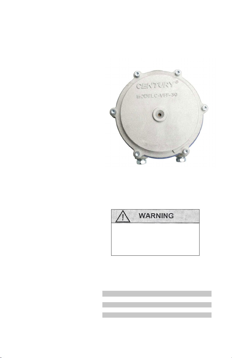
MODEL C-VFF30 LOCKOFF/FILTER
REPAIR KIT INSTRUCTIONS

Page 2 of 14 C-VFF30 Repair Kit Instructions (Form 103-2)
MODEL C-VFF30 LOCKOFF/FILTER COMPONENTS
ITEM# PART# DESCRIPTION
1* C-S1-15265-001 Screw, 8-32 Taptite (6)
2 C-C1-37 Diaphragm cover,
(std., C-VFF30 only)
3* C-BD1-26 Diaphragm Assy,
Standard (C-RK-VFF30)
C-BD1-27 Diaphragm Assy, Silicone
(C-RK-VFF30-2)
C-BD1-27-5 Diaphragm Assy,
Blue
(C-RK-VFF30-3)
4* C-S1-15265-002 Screw, 8-32 Taptite (3)
5 C-F3-2 Fulcrum
6 C-L1-39 Valve operating lever
7 C-AB1-30149 Body ass’y
8 C-S1-15 Screw, 1/4-20 x 5/8”
SEMS (2)
9* C-S3-116 Seal, Lip Pin
10* C-P1-15 Valve, operating pin
11 C-S2-40 Valve, spring
12* C-S7-3 Screen, back-up lter
13* C-F1-10 Filter
14* C-AF1-10 Filter ass’y
15* C-G1-89 Filter cover gasket
16 C-C1-38 Filter cover
17 *C-S1-15266-001 Screw, 12-24 Taptite (10)
18 C-AF4-66 Fitting, ball check,
assy (not shown)
19 C-S4-18 Seat, C-VFF30
20* C-W1-42 Washer, Seal Retaining
NSS = Not Serviced Separately
* Repair Kit Components. Note that extra
screws (both slotted and torx) are included
in the repair kits to replace any that may be
damaged. When replacing screws, be sure
to properly match thread type (self-tapping
or machined) as the two types are not
interchangeable.

Page 3 of 14 C-VFF30 Repair Kit Instructions (Form 103-2)
REBUILD INSTRUCTIONS
Disassembly
1. Remove 10 screws from “Fuel In”
cover.
2. Remove cover and C-GI-89
gasket.
3. Remove C-F1-10 lter and screen
C-S7-3.
4. Remove C-S1-15265-002 screw
retaining valve spring.

Page 4 of 14 C-VFF30 Repair Kit Instructions (Form 103-2)
5. Remove valve spring.
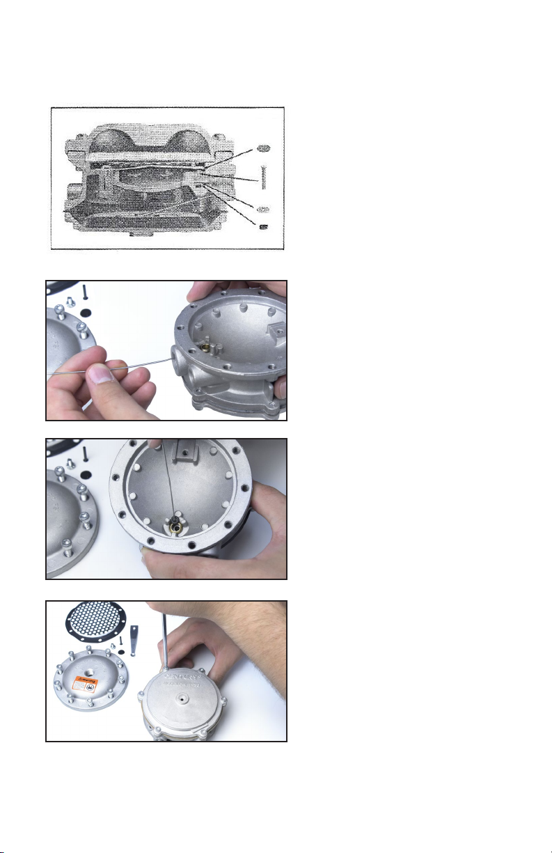
6. Using a small at head
screwdriver, remove C-S4-18 valve
seat.
7. Gently lift up and remove the
C-P1-15 valve operating pin.
8.With paper clip or wire, fashion a
hook as shown.
Page 5 of 14 C-VFF30 Repair Kit Instructions (Form 103-2)
9. Cutaway show assembly of valve
spring, valve seat, valve operating
pin, seal retaining washer and pin lip
seal. Note that removal of valve pin
allows retaining washer to be removed
through the 1/4” NPT opening labeled
“Out”.
10. Insert paper-clip hook in center
hole of C-W1-42 seal retaining washer
and remove.
11. Using the same hook, remove the
pin seal C-S3-116 through valve jet.
12. Remove 6 screws on diaphragm
cover side.

Page 6 of 14 C-VFF30 Repair Kit Instructions (Form 103-2)
13. Remove cover and diaphragm
assy. Clean covers, body and metal
parts as necessary with a safety
solvent and dry prior to reassembly.
Do not use harsh solvents such as
brake or carburetor cleaner on any
of the non-metallic components as
they will damage this material.

Page 7 of 14 C-VFF30 Repair Kit Instructions (Form 103-2)
14.
1
1
1
1
2
2
1
1
1
1
1
1
1
2
2
1
*Standard diaphragm. See table on page 2 for
optional diaphragms.
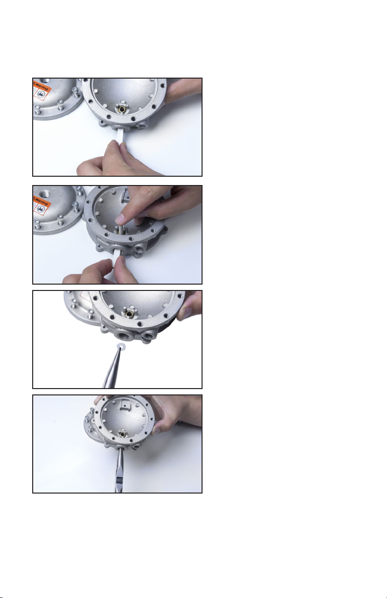
15. Lubricate the Lip Pin Seal C-S3-
116 with petroleum jelly or Vaseline
and insert into the Holder C-H1-
14236 groove side up, as shown
in the illustration. Note that the
C-H1-14236 Seal Holder passage is
tapered and the wide opening of the
seal holder should be facing up.
16. Place the C-VFF30 body with the
lter side up, as shown in the photo,
on a at surface. Ensure that the
groove in the seal is visible from the
top of the taper of the seal holder.
Reassembly
C-GI-89 Gasket
C-RK-VFF30 Kit Includes:
C-F1-10 Filter
C-S7-3 Screen
C-BD1-27* Diaphragm Assy
C-S1-59 Screw, 8-32 x 5/8”
C-S1-100 Screw, 12-24 x 5/8”
C-S4-18 Seat (Viton Bonded to Aluminum)
C-S3-116 Seal, Lip Pin
C-PI-15 Pin, Valve Operating
C-W1-42 Retainer Washer 1
C-H1-14236 Seal Holder Insertion Tool
C-P1-14235 Pin Insertion Tool
Form 103-2 Instructions
C-S1-15265-001 Screw, 8-32 17/32” Taptite Torx
C-S1-15266-001 Screw, 12-24 x 11/16 Torxl
C-S1-15265-002 Screw, 8-32” 3/8” Taptite Torx
Page 8 of 14 C-VFF30 Repair Kit Instructions (Form 103-2)
17. Place the holder in the up
position and slide the holder into the
seal into the body of the C-VFF30.
Looking through the fuel port,
position the seal above the cavity of
the seal recess.
18. Coat the installation pin C-P1-
14235 with petroleum jelly and push
the seal through the holder and into
the seal recess of the C-VFF30 body.
Look through the fuel port to ensure
the seal is seated in the seal recess
and that the groove in the seal is
visible.
19. Use needle nose pliers to hold
C-W1-42 seal retainer washer.
20. Insert seal retainer washer in
slot to hold the lip seal in place.
Page 9 of 14 C-VFF30 Repair Kit Instructions (Form 103-2)
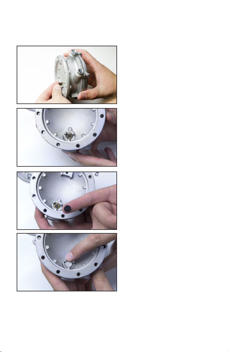
21. Lubricate pin with petroleum jelly
and insert through hole in retainer
washer and pin lip seal. Again rotate
head of pin gently in a circular motion
to ease pin into place through washer,
lip seal and body housing.
22. Pin C-P1-15 is properly placed in
valve jet.
23. Valve seat shown with aluminum
side up ready to be placed on jet.
24. Place the seat with the viton (black
rubber) side down, in position on jet.

Page 10 of 14 C-VFF30 Repair Kit Instructions (Form 103-2)
25. C-S2-40 spring ready to be
fastened in place. Be sure the arc
in the center faces upward (see
illustration in step 26 below).
26. Replace spring and fasten in
place by C-S1-15265-002 screw
(8-32). Align the tip of spring (over
valve) and center between the 3
guide ns as shown in illustration.
Tighten screw to 30 +/-3 in-lbs.
27. When spring is in place, lift
slightly to ensure it can move freely.
28. Insert C-S7-3 screen and lter
C-F1-10 into recess.
Page 11 of 14 C-VFF30 Repair Kit Instructions (Form 103-2)
29. Press C-F1-10 lter so that it is
properly seated in recess.
30. Place C-G1-89 gasket in place
and align with screw holes.
31. Insert screws opposite each
other in the “Fuel In” cover and
place on gasket. Thread the two
screw C-S1-15266-001 through the
gasket and into the body.
32. Insert remaining 8 screw in their
openings.

Page 12 of 14 C-VFF30 Repair Kit Instructions (Form 103-2)
33. Tighten screws, alternating from
side to side on opposite sides of the
cover until all screws are solidly set.
Torque to 65+/-5 in-lbs.
34. Lift lever C-L1-39 to ensure it
moves properly and verify that the
C-P1-15 lever control pin follows lever
travel.
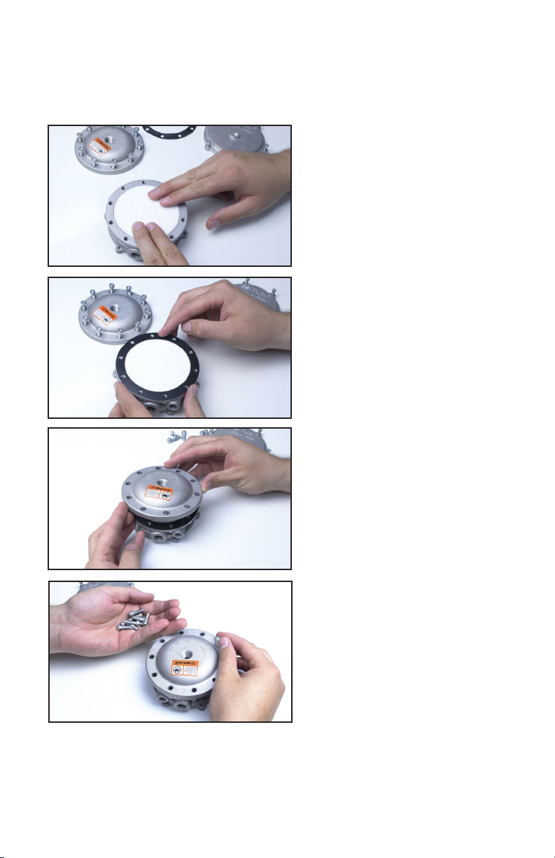
35. Turn diaphragm so the raised lip
is downward (see illustration on page
2) place on the Lockoff and rotate to
position so the screw hole pattern
aligns with the holes in the body
(there is only one position in which
the holes will line up).
36. Place cover in correct position and
insert screws C-S1-15265-001.

Page 13 of 14 C-VFF30 Repair Kit Instructions (Form 103-2)
37. Tighten screws alternatively
from side to side across cover until
all are solidly fastened. Torque to
30 +/-3 in-lbs.
38. Pressurize the “Fuel In”
opening with approximately 100
psi of air pressure. Draw a soap
bubble across the Lockoff outlet
and vacuum port (labeled “VAC”) to
verify that no air is owing through
either opening. If air escapes, the
rebuild has failed and the Lockoff
must be replaced. Apply a small
amount of vacuum to the port
labeled “VAC” to verify the air ows
freely through the outlet. Use soap and/or a commercial leak detector solution
to inspect the gasket seals around the perimeter of the Lockoff for leaks. If leaks
are found, the Lockoff must be replaced. If no leaks are found, the Lockoff can be
reinstalled and returned to service.

Page 14 of 14 C-VFF30 Repair Kit Instructions (Form 103-2)
SERVICE TECHNICIANS AND USERS
SHOULD CAREFULLY READ AND ABIDE BY THE PROVISIONS SET FORTH IN
NATIONAL FIRE PROTECTION ASSOCIATION PAMPHLET #37 FOR STATIONARY
ENGINES, #52 FOR CNG VECHICULAR FUEL SYSTEMS OR #58 FOR LPG
SYSTEMS.
IN CANADA
REFER TO CAN/CGA PROPANE INSTALLATION CODES
CNG INSTALLATIONS IN THE UNITED STATES
MUST BE DONE IN ACCORDANCE WITH FEDERAL STATE OR LOCAL LAW AND
NATIONAL FIRE PROTECTION ASSOCIATION PAMPHLET #52, COMPRESSED
NATURAL GAS (CNG) VEHICULAR FUEL SYSTEMS TO THE EXTENT THESE
STANDARDS ARE NOT IN VIOLATION WITH FEDERAL, STATE OR LOCAL LAW.
IN CANADA
REFER TO CAN/CGA CNG INSTALLATION CODES.
LPG AND/OR NATURAL GAS INSTALLATIONS ON STATIONARY
ENGINES
MUST BE DONE IN ACCORDANCE WITH FEDERAL, STATE OR LOCAL LAW AND
NATIONAL FIRE PROTECTION ASSOCIATION PAMPHLET #37, STATIONARY
COMBUSTION ENGINES AND GAS TURBINE ENGINES, TO THE EXTENT THESE
STANDARDS ARE NOT IN VIOLATION WITH FEDERAL, STATE OR LOCAL LAW.
FAILURE TO ABIDE BY THE ABOVE WILL VOID ANY IMPCO WARRANTY ON THE
PRODUCTS AND MAY CAUSE SERIOUS INJURY OR PROPERTY DAMAGE.
DUE TO THE INHERENT DANGER OF GASEOUS FUELS THE CENTURY PRODUCTS
SHOULD NOT BE INSTALLED OR USED BY PERSONS NOT KNOWLEDGEABLE
OF THE HAZARDS ASSOCIATED WITH THE USE OF GASEOUS FUELS.
WARNING:
IMPROPER INSTALLATION OR USE OF THIS PRODUCT MAY
CAUSE SERIOUS INJURY AND/OR PROPERTY DAMAGE.


